|
|
|
|
|

|
|
Micro-Tel Bugs MSR-903 → ← MSR-901
Like its predecessor, the MSR-901,
the device is usually housed in
standard Samsonite briefcase or — as shown in the image on the right —
in a larger Samsonite suitcase, along with
one or two tuners that cover the entire 1-26 GHz range.
The actual receiver has a rectanglular shape and is painted in the typical
Micro-Tel mint colour. The control panel is at the top, which allows operation
from within a briefcase. When present, the tuners are fitted in the remaing
space of the supporting frame. Any cables and accessories are stored in the
top lid of the Samsonite case.
|
|
|
|
The following versions of the MSR-902 are currently known:
|
- MSR-902
This is the initial version of the MSR-902 as it was released in the mid-1980s.
It is an all-in-one unit that has a frequency coverage of 1-18 GHz. Antenna
inputs are at the front right of the control panel. There are three N-type
sockets for: (1) 1-12 GHz antenna, (2) 12-18 GHz antenna and (3) External mixer.
The version is usually housed in a standard Samsonite briefcase, much like
its predecessor, the 1-12 GHz MSR-901.
➤ Photograph
- MSR-902C
This is the version that is featured on this page. It has no built-in
tuners, but fully relies on two external tuners: a large one for the 1-18 GHz
range, and a smaller one for 18-26 GHz. For this reason, the set is
housed inside a larger Samsonite suitcase.
|
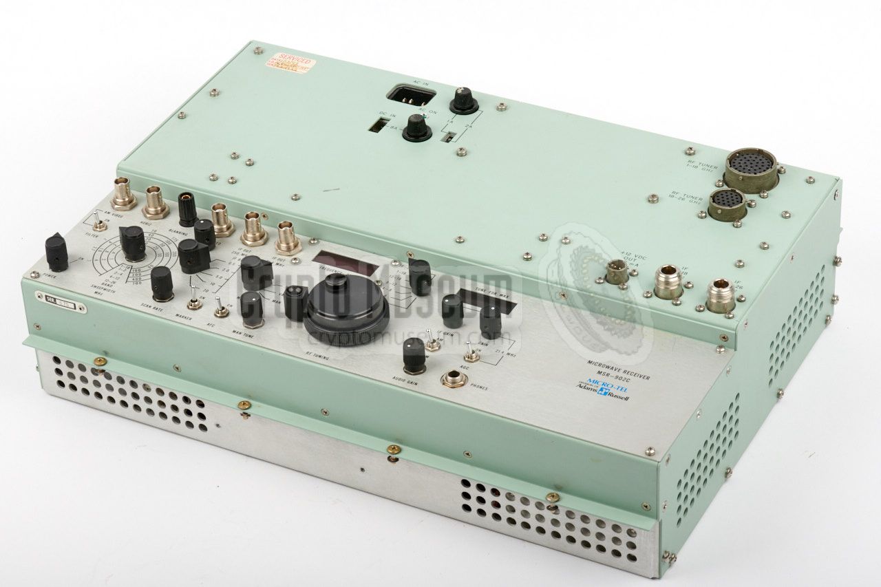
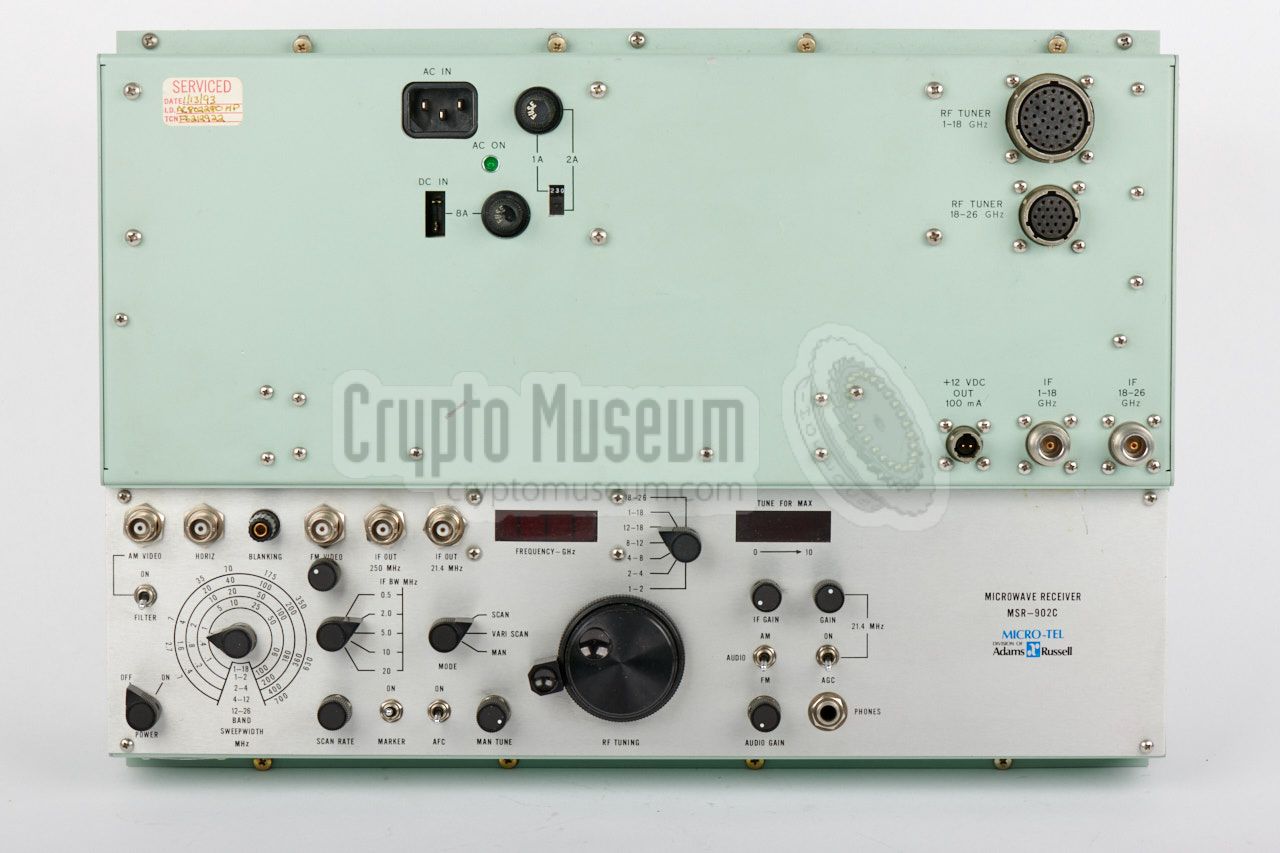
The diagram below sbows the top panel of the MSR-902C, which is slightly
different from the MSR-902. The upper 2/3 holds the sockets for connection
of the power sources and the two tuners,
whilst the lower 1/3 holds the
control panel, with the large two-speed tuning dial at the centre.
Above the tuning dial are the frequency readout, the band selector and
a tuning indicator. At the bottom left is the POWER switch (ON/OFF), whilst
the mains should be connected to the EURO-receptacle at the top.
Ensure that the correct voltage is selected before turning it on.
To the left of the tuning dial are the controls for selection the bandwidth
and operating the internal scanning features. The big dial at the far left is
for selecting the width of the sweeping range. The sockets at the the top left
are for connection of an oscilloscope, that can be used as a panoramic display.
There are also two sockets for the IF outputs (250 MHz and 21.4 MHz).
To the right of the frequency dial are the demodulator and output controls.
On the earlier MSR-902, the empty section at the right holds the
two antenna inputs
for the 1-18 GHz and 18-26 GHz ranges. They are omitted on the
MSR-902A, as on that version the antennas are connected to the tuners.
|
The diagram below shows the configuration for two known versions of
the MSR-902. At the left is the initial version, in which the tuner
is housed inside the main device. The tuner has two inputs: one for
each range (1-12 GHZ and 12-18 GHz). At the right is the MSR-902C
that is featured on this page. It has two separate tuners that
are fitted externally: one for the initial 1-18 GHz range,
divided over two sub-ranges with separate inputs,
and an optional one for the 18-26 GHz range.
...
|
|
The initial version of the MSR-902 was usually housed inside a
standard Samsonite briefcase of the era, much like its predecessor
the MSR-901.
|
|
|
|
With the MSR-902C, the two tuners are fitted externally, which means
that the standard Samsonite briefcase shown above, is not large
enough. For this reason, the MSR-902C was fitted inside a larger
Samsonite travel suitcase, such as the one shown in the image on
the right.
|
|
|
The actual receiver can be recognised by its typical main colour,
and is usually fitted in the bottom section of the briefcase.
All controls and connections are located at the top surface. The
receiver is also known as the main unit.
With the MSR-902, the tuners are fitted internally and their
inputs are located at the front right of the control panel.
With the MSR-902C, the tuners are fitted externally and are
connected to the receiver via a set of cables.
|
|
|
This tuner is for reception of the 1-18 GHz range and is the largest
of the two tuners that can be fitted to the MSR-902C. It is commonly
mounted to the right of the main unit and is connected to it via a short
coaxial cable (IF) and a thick multi-wire cable (control).
The tuner has two inputs: one for the 1-12.6 GHz range and one for the
12.6-18 GHz range. The output is delivered to the main unit via a
single short IF cable.
➤ Look inside
|
|
|
Optionally, a second tuner can be fitted for the 18-26 GHz range.
It is much smaller than the 1-18 GHz one, and is usually fitted
behind the main unit. Like tuner 1, it is connected to the main
unit by means of a coaxial cable (IF) and a (thick) control cable.
➤ Look inside
|
|
|
With the MSR-902C, the two tuners are fitted externally, which means
that they will hvae to connected to the main unit. At both tuners
contain electronically adjustable YIG filters, a rather thick control
cable is needed between the tuners and the main unit. The output
of each tuner is delivered via a short coaxial cable.
Control cables for the MSR-902 are extremely rare. They are available
in two variants: short and long. The short ones are used when the unit
is installed in a Samsonite case, whilst the long ones are for detached
use and maintenance.
|
|
|
The difficulty with an UHF/SHF receiver like the MSR-902, is finding
one or more antennas that are suitable for the extremely high frequencies
and the wide band coverage. Although it is not possible to find a single
antenna that covers the entire frequency range, it should be possible to find
antennas that cover the individual bands that are supported by the external
converters.
The image on the right shows a very rare Dyson dual element
conical spiral antenna that is
suitable for the 1-12 GHz frequency range.
➤ More information
|
|
|
The MSR-902 was supplied with an Operating and Instructions Manual
and (optionally) with a full Service Manual that contains detailed
circuit descriptions and diagrams.
Unfortunately, neither of these manuals is currently available to
us. If you have any of these manuals, we would be very
pleased to receive a copy or a scan.
➤ Contact us
|
|
|
...
... broken YIG oscillator ...
|
|
As with most complex devices that are more than 30 years old,
it may be necessary to carry out a few repairs in order to bring
it back to life. With the MSR-902C featured on this page, this was no
different. In this particular case, most of the repairs, and hence
the restoration, was carried out by the previous owner,
Dr. Simon Schrödle in Germany, who has
described the repair in great detail
on his excellent web blog: Simons Dialogs
[1]. Among other things, he did the following:
|
- Dead PSU repaired (broken MJ12002 transistor)
- A3B5 and A3B6 boards repaired (broken 7401, 7404, transistor and LEDs)
- Filter properly mounted (caused short-circuit on the +15V rail)
- Frequency readout fixed (broken reference diode)
- Research broken YIG oscillator in 18-26 GHz tuner (not fixed) [2]
Frequency 1-18 GHz (optionally also: 18-26 GHz)
|
Device Microwave surveillance receiver Purpose Surveillance, satellite downlink, intelligence gathering Model MSR-902, MSR-902C Manufacturer Micro-Tel Country USA Year 1989 Predecessor MSR-901 Frequency 1-18 GHz, extendable to 100 GHz using external harmonic mixers Noise 20dB 1 1-18 GHz Readout 4-digit LED display, accuracy ±1%, +1 digit Tuning Electronic Modes ➤ see tuning modes Preselection Auto-tracked 3-section YIG filter in all tuning modes Indicator Uncalibrated signallevel meter AFC 10:1 correction Ant. cond. <-70dBm, +60dBm above 12 GHz RFI Fully RFI protected Image rej. >70dB, 60dB above 12 GHz IF rejection >80dB RF inputs Type N, 50Ω nominal IF gain control 60dB range IF bandwidths 0.1, 1, 20 MHz (linear) 2 IF output 10 MHz bandw. at 250 MHz, ≤-6dBm at 50Ω, 14dB gain from mixer Demodulator AM, FM Audio 5.0 mW 600Ω, phone jack, variable gain Sweep rate 0.1 - 30 Hz (variable) Oscilloscope Hor: 3Vpp DC 1000&Omega. Blanking: +5V pulse at 5000Ω Power 115/230VAC, 50-400Hz, 75W / +12V DC, 50W Size Attache case: 17 x 12 x 5 inches Weight 35 pounds
|
 |
|
-
Typical over 90% of the band. Add 3db for maximum noise figure.
-
Other linear bandwidths available on special order (0.1-20 MHz).
10 MHz Log IF available.
|
- 1-12.6 GHz
- 12-18 GHz
- 18-26 GHz
|
Scan Full band sweep at variable rate with manually tuned frequency marker Var Scan Variable 0 to ±5% sweep around center frequency Man Dual-speed control of frequency, with veneer
|
1 MSR-902 receiver (main unit) 2 Provision for external harmonic mixers 18-100 GHz 2A Provision plus external mixers 18-40 GHz 3 Log IF Amplifier - 10 MHz bandwidth 1 4 21.4 MHz IF output 2 5 Additional IF bandwidth 1
|
-
Options 3 and 5 are not available together.
-
Option 4 can be installed only if internal battery is not fitted.
+12V DC external power capability is maintained.
|
VDA-60 Video Display Analyzer AK-902 Accessory Kit
|
|
At present, the YiG oscillator of the 16-28 GHZ converter is broken.
Crypto Museum are looking for a replacement YiG oscillator, and also for
the full service manual and circuit diagrams of the MSR-902C.
If you can supply any of the following items, please contact us:
|
- YiG oscillator for 18-26 GHz tuner: Avantek S081-0321
- MSR-902C user and service manual
- Short control cable for 1-18 GHz tuner
- AK-902 Accessory Kit
|
-
Obtained via Terry O'Laughlin, Black Radios website.
➤ More
|
|
|
|
Any links shown in red are currently unavailable.
If you like the information on this website, why not make a donation?
© Crypto Museum. Created: Wednesday 18 October 2017. Last changed: Saturday, 15 March 2025 - 16:12 CET.
|
|

|
|
|


![Original MSR-902 with built-in tuners and battery, photograph via eBay [2]](img/msr902_ebay_thumb.jpg "image # msr902_ebay.jpg")
![Original MSR-902 with built-in tuners and battery, photograph via eBay [2]](img/msr902_ebay.jpg)