|
|
|
|
|

|
|
TSCM Mason A-2CS → ← A-1
Portable intercept receiver
The A-2 was a
technical surveillance and countermeasures (TSCM) receiver,
developed in 1964 by Mason Engineering Inc as the successor
to the A-1.
The modular A-2 was developed by company
director Frank Mason himself, and was hand-built at the factory in Fairfield
(Connecticut, USA) for 16 years at a rate of one unit per week [1][3]. 1
It is capable of detecting covert listening devices (bugs) operating
in the 2 kHz - 2 GHz range. 2
The Mason A-2 was used by law enforcement and intelligence agencies in
the US and in Europe, including the UK, Germany and the Netherlands.
|
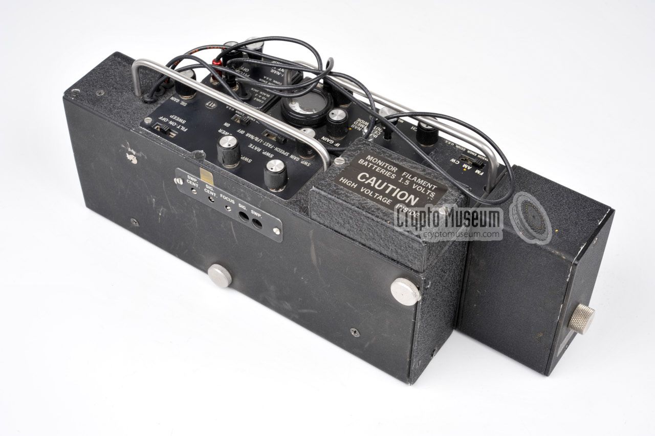
Visually, the A2 is one of the most interesting members of the
Mason family.
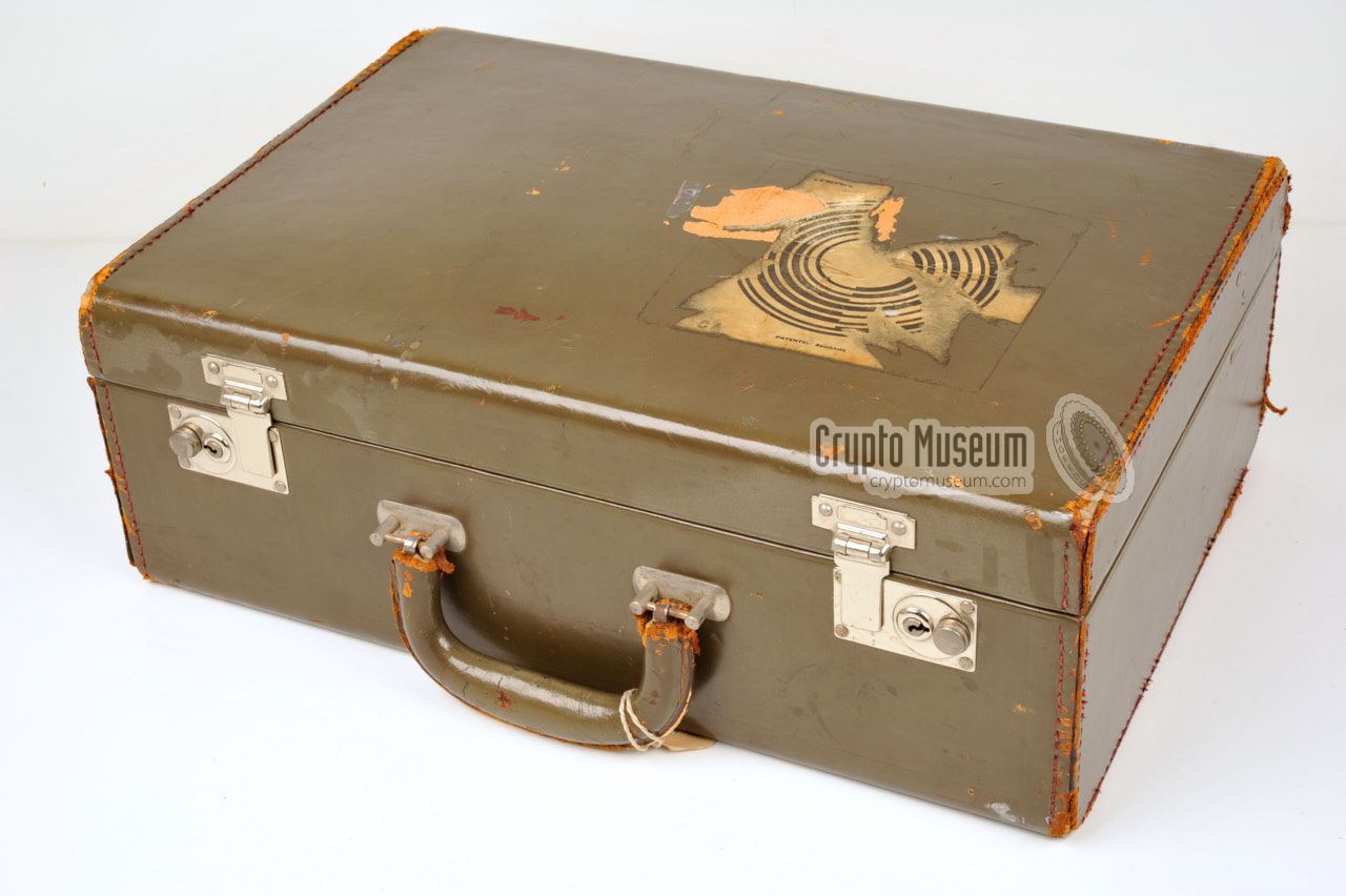
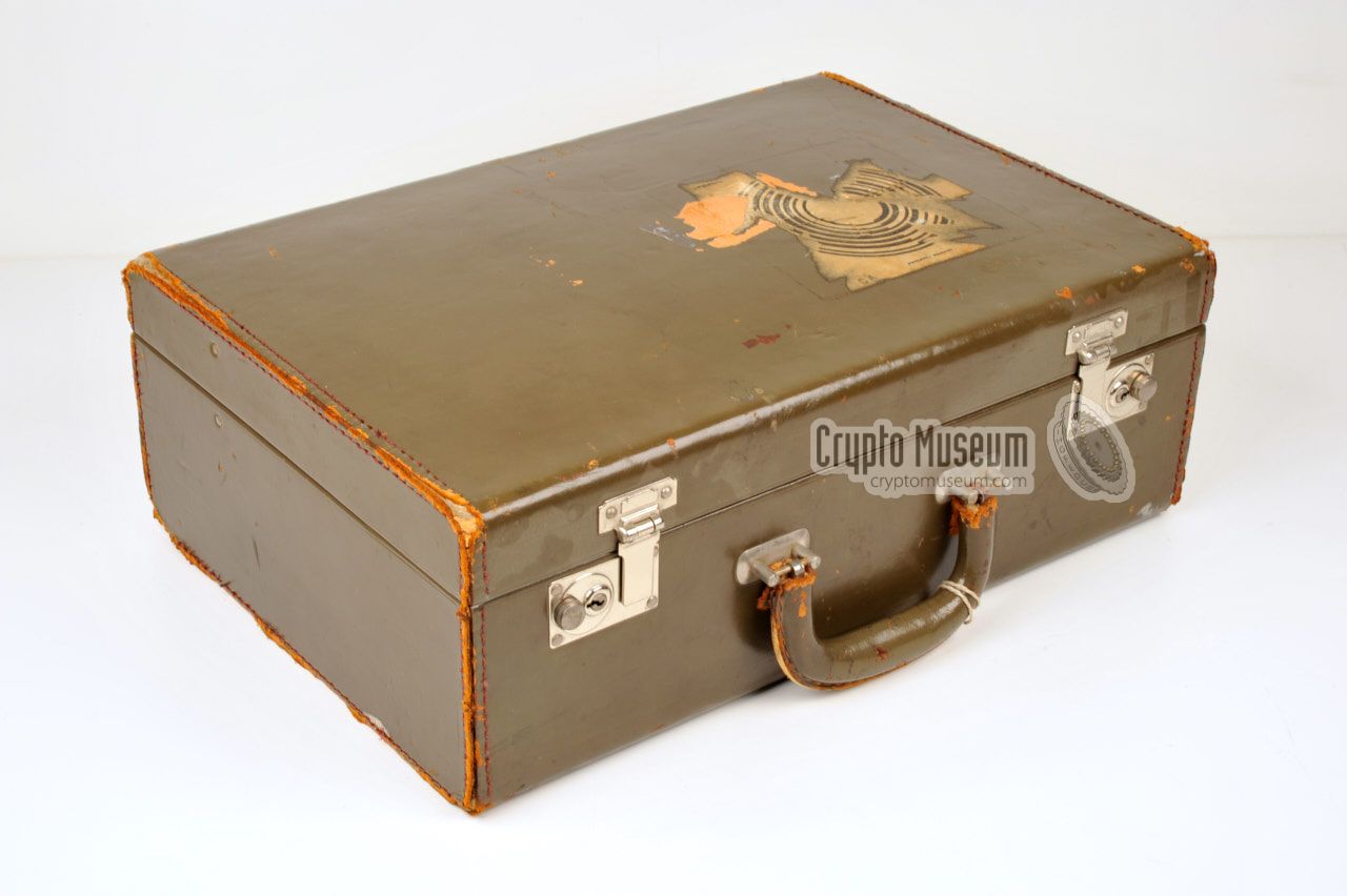
The unit is stored inside an unobtrusive
leather suitcase,
together with a range of
accessories and plug-in units.
The main unit consists of a small receiver
with a somewhat larger display unit bolted to its side.
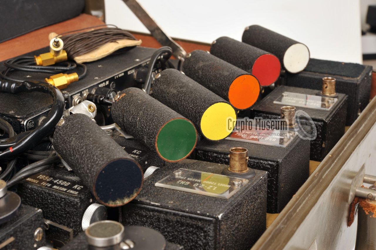
The various plug-in units
are attached to the right side of the receiver.
Each tuner is identified by a model number and in some
cases a unique colour at the circular front cover
of the antenna.
The display unit is basically an oscilloscope that is used
as a panorama viewer, with its cathode
ray tube (CRT) sticking out at the right. The CRT is slightly tilted,
so that it can be viewed without tilting the receiver. On later
receivers, such as the A-3B, a hinged mirror was mounted
over the CRT screen, which greatly improved its usability.
|
|
|
Over the years, the A-2 was modified and improved several times, resulting
in different versions.
Note that the tuners of the A-2B are not interchangeable with those
supplied with the earlier A-2.
Furthermore, the coloured caps on the ferrite antennas of the TLF tuners
were not present on the initial version.
A complete all-in-one version in an aluminium case, is available as the
A-2CS.
Although the A-2 was succeeded by the A-3 in 1971,
it remained in production until mid-1990.
During this time, approx. 800 hand-built units 1 were made [3].
At the time of its introduction in 1964, the A-2 had a price tag of $5,000,
but by 1975 this had doubled to $9,995. And ten years later, in 1985,
the price had even increased to $14,950. Nevertheless, the A-2 was a
very reliable product with an extremely long lifespan.
The 1966 sales brochure can be
downloaded below [A].
|
 |
-
Altough it is believed that during the 16-year lifespan of the A-2,
only 800 units were built [3] at a rate of one unit per week,
there are also claims that approx. 1800 units were built [2]. We believe
the former (800) to be correct.
-
The initial version of the A-2 covered 2 kHz - 1.1 GHz, but later versions
of the A-2 and also the A-2B covered the full frequency range up to 2 GHz.
|
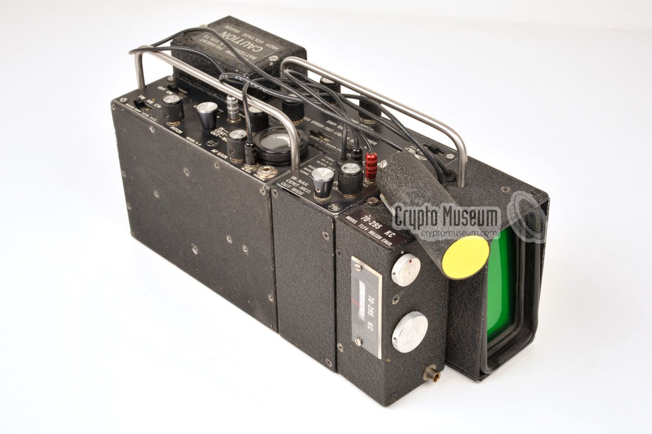
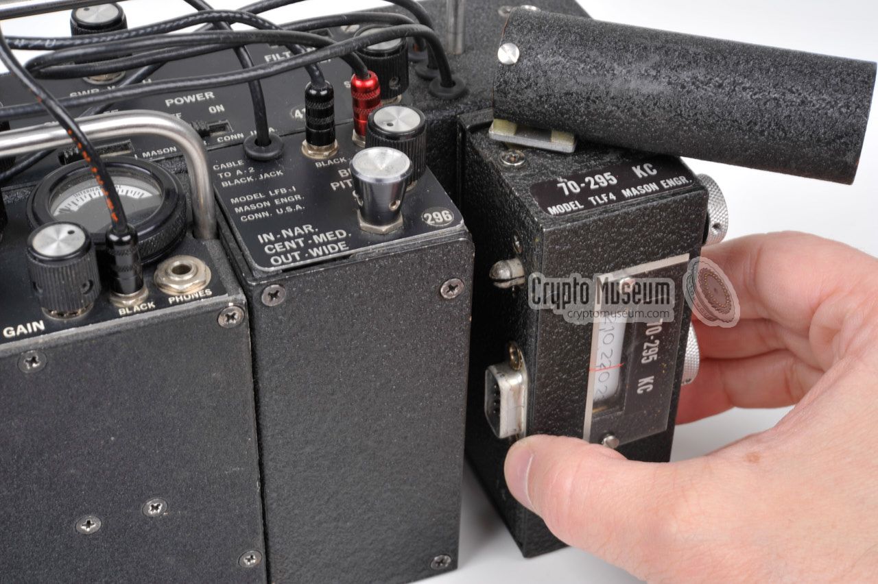
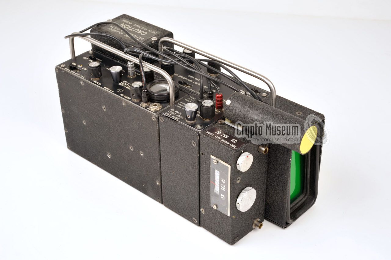
The diagram below provides a quick overview of the Mason A-2 receiver.
The actual receiver is at the front left with the CRT unit behind it.
The slightly tilted green phosphor display [5] of the CRT unit is just
visible at the far right.
To the right of the receiver is an adjustable IF unit and finally a
pluggable tuner with its frequency scale at the front. In the image below,
the 70-295 kHz tuner is mounted, which can be identified by the
colour-coded (yellow) disc at the front of its antenna.
On the internal batteries, the A-2 can be used for 35 hours, or 15 hours
when the display unit is in used. When using the optional external BP-3
battery pack, the A-2 can be operated for 120 hours (or 60 when the panorama
display is switched on). Three power switches are important:
|
A-2 ON/OFF switch S-1 Panorama Unit (display unit) LFA-1 Audio amplifier, battery pack and S-meter (not shown here)
|
|
In order to cover the full frequency range from 2 kHz to 2 GHz,
the A-2 is supplied with no less than
12 plug-in units
or tuners.
Each tuner covers a specific frequency range and is plugged into the
right side of the main unit, in some cases via the LFB-1 unit. To get a
better understanding of the concept of tuners, we will divide them into
two groups: the low frequency (LF) tuners
that are used for the 2 kHz to 4.5 MHz range,
and the high frequency (HF) tuners (4.5 MHz - 2 GHz).
|
|
|
LF tuners
2 kHz - 4.5 MHz
|
|
|
|
Tuners TLF-1 ··· TLF-6 each have a movable built-in ferrite antenna
that is mounted at the top. In addition it is possible to connect an external
wire antenna or a mains antenna. When these tuners are used, the
IF amplifier LFB-1 always has to be connected between the tuner and the
main unit.
|
|
|
HF tuners
4.5 MHz - 2 GHz
|
|
|
Tuners T-18 ··· T-2000 are always connected directly to the
basic unit
(i.e. no LFB-1).
These tuners do not have a built-in antenna and require
a suitable telescopic antenna to be inserted from the right.
Three different telescopic antennas are supplied to cover the entire range.
The band spread of the higher frequency tuners is remarkable to say the least.
For example: the T-340 tuner covers two octaves (75 - 340 MHz), which clearly
demonstrates Mason's experience
as a designer of television tuners during the
1950s, before founding his own company in 1961.
|
|
The following tuners were supplied with the initial version
of the A-2 in 1964:
|
TLF-1 2-9 kHz 1 TLF-2 9-43 kHz 1 TLF-3 43-130 kHz 1 TLF-4 130-475 kHz 1 TLF-5 475-1470 kHz 1 TLF-6 1470-4500 kHz 1
T-5 50 kHz - 4.5 MHz (no RF) 2 T-18 4.5 - 18 MHz 2 T-75 18 - 75 MHz 2 T-340 75 - 340 MHz 2 T-900 340 - 900 MHz 2 T-1100 700 - 1200 MHz 2
|
-
AC-1, LFB-1 and A-2 (or LFA-1) required.
-
AC-1 and A-2 required.
|
|
At some point, the upper frequency limit of the A-2 was extended to 2 GHz,
by replacing the upper two tuners (T-900 and T-1100) by three new ones.
At the same time, The ranges for tuners TLF-1 ··· TLF-6 were changed,
and tuner T-5 was dropped.
|
TLF-1 ● 2-6 kHz 1 TLF-2 ● 6-19 kHz 1 TLF-3 ● 18-70 kHz 1 TLF-4 ● 70-295 kHz 1 TLF-5 ● 295-1050 kHz 1 TLF-6 ● 1050-4500 kHz 1
T-5 50 kHz - 4.5 MHz (no RF) 2 T-18 4.5 - 18 MHz 2 T-75 18 - 75 MHz 2 T-340 75 - 340 MHz 2 T-650 340 - 650 MHz 2 T-1200 650 - 1200 MHz 2 T-2000 1200 - 2000 MHz 2
|
|
It is not known from which serial number this change took effect, but
the A-2 in our collection, with serial number 417, has the extended range.
This range was also used for the A-2B.
|
-
AC-1, LFB-1 and A-2 (or LFA-1) required.
-
AC-1 and A-2 required.
|
|
All tuners can be operated when detached from the main unit, by using
one of the special cables. For the TLF tuners, a short 50 cm multi-wire
cable is supplied. Note that in this mode of operation the fixation bolt
has to be removed from the tuner, in order to avoid spurious noises.
|
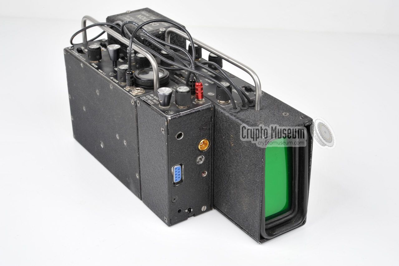
It was possible to convert the A-2 into a body-wearable receiver,
suitable for concealed or covert operation, by using an optional
belt clip. In this configuration, the panorama viewer was removed from
the set and the bare receiver (A-2 basic unit) was used in combination with
a battery pack and one of the tuners.
For the lower frequency tuners (TLF), the IF unit (LFB-1)
also had to be present, as shown in the image on the right. A 50 cm
multi-wire cable,
with DB-9 male/female connectors, is used to connect the selected
tuner to the LFB-1 unit.
|
|
|
For the higher frequency (T) tuners, a 60 cm piece of
coaxial cable
was supplied, which allowed the tuner to be connected directly
to the A-2 basic unit.
|
The complete A-2 receiver, with all plug-in units, accessories and
documentation, came in an unobtrusive leather suitcase that measures
roughly 15 x 31x 45 cm and weighs ~ 5 kg.
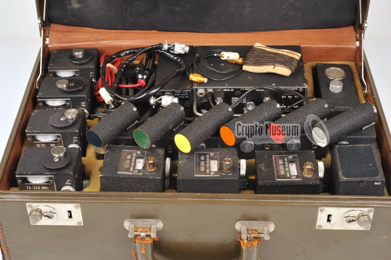
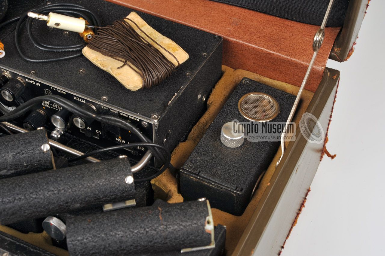
Inside the briefcase is a pre-shaped foam interior that holds all
parts. Each unit has its own tightly-fitting compartment. This way,
the parts are well protected during transport and any missing
units are easily spotted.
|
|
|
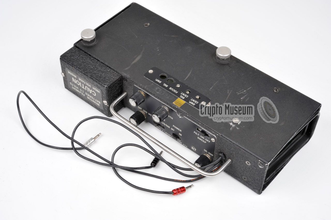
The actual receiver is marked 'A-2' and is fairly small. It
contains an IF-stage, an AF-amplifier and the S-meter. All
other modules connect to the A-2 which acts as the Basic Unit.
The battery pack (BP-3) or mains power supply unit (PS-2)
can be attached to the left side of the A-2, whilst the LFB-1
and/or the tuners are fitted at the right side. The T-tuners
can be fitted directly, whilst the TLF-tuners require the
LFB-1 unit to be fitted as well.
|
|
|
The A-2 receiver has its 1st IF frequency at 23.5 MHz. For the lower
frequencies (LF), this means that the signal has to be 'up-converted'
before it can be detected by the A-2 receiver.
The LFB-1 unit has to be inserted between any
TLF-tuner and the
A-2 Basic Unit,
and contains an IF-strip, a Beat Frequency Oscillator (BFO)
and an AM detector.
A 'flying wire' with a black mini jack plug has to mate with the socket
marked 'black' on the A-2 unit.
If the panorama viewer (S-1) is used,
two of its wires (black and red) should be connected to the LFB-1.
|
|
|
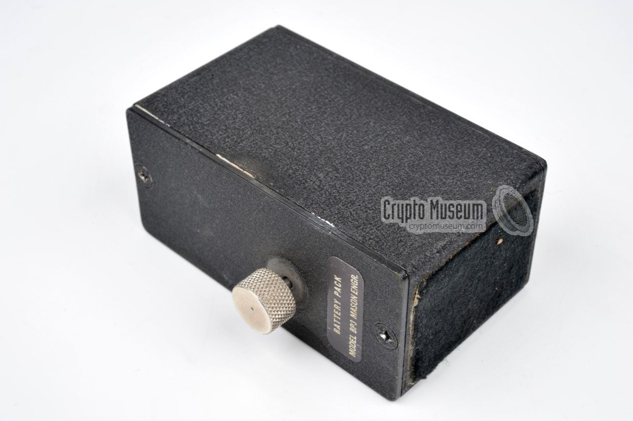
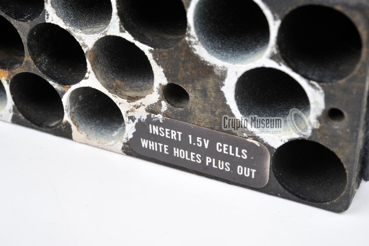
For portable use, the A-2 could be powered by batteries,
by using the BP-3 battery pack. The BP-3 takes 14
AA-size penlight batteries of 1.5V each, giving a total
of 18.8V DC.
The BP-3 was attached to the left side of the A-2 Basic Unit.
The device could be operated for 120 hours, or 60 when the
panorama viewer (S-1) was installed as well.
In the latter case, the S-1 unit needs two extra batteries for
the filaments of the Cathode Ray Tube (CRT).
|
|
|
For stationary use, the A-2 was best used in combination with the
mains power supply unit PS-2. It was installed at the left side of
the A-2 Basic Unit, instead of the BP-3 battery pack.
The PS-2 is suitable for a wide range of AC mains voltages,
that can be selected with a slide switch at its back.
The image on the right shows a typical PS-2 unit with a US
wall socket plug.
|
|
|
Warning: be careful when connecting the PS-2 after
so many years of inactivity, as its capacitors my have dried out
by now, and the mains wiring may have become brittle.
Connect and use the PS-2 only if you known exactly what you
are doing.
|
|
In order to cover the full frequency range from 2 kHz to 2 GHz,
the A-2 is supplied with no less than
12 plug-in units
or tuners.
Each tuner covers a specific frequency range and is plugged into the
right side of the main unit, in some cases via the
LFB-1 unit. To get a
better understanding of the concept of tuners, we will divide them into
two groups: the low frequency (LF) tuners
that are used for the 2 kHz to 4.5 MHz range,
and the high frequency (HF) tuners (4.5 MHz - 2 GHz).
|
Each A-2 receiver was supplied with 6 tuners to cover the
lower frequencies in the 2 kHz to 4.5 MHz range. These tuners
are marked with TLF-numbers and cover the Long Wave (LW),
Medium Wave (MW) and partly the Short Wave (SW) bands.
Each TLF tuner has its own ferrite antenna mounted at its top,
that could be rotated for maximum or minimum signal strength.
In addition, a wire antenna
or a mains antenna could
be connected to the side of the tuner.
It was also possible to connect one of the supplied telescopic
antennas, but with limited effect.
|
|
|
The exact band spread of each TLF tuner differs between the various
A-2 variants, but the total frequency range was always 2 kHz to
4.5 MHz. The different sets are listed below. Note that the
variants with the colour-coded ferrite antenna caps were the most
common ones.
Also note that when the TLF tuners are used, the LFB-1 module
also has to be present. It contains the IF-strip, the BFO and
the AM detector and is connected between the TLF tuner and the
A-2 Basic Unit.
|
The higher frequencies, from 4.5 MHz to 2 GHz, are covered by
another set of 6 tuners, marked with T-numbers. These tuners
cover the HF, VHF, UHF and partly the SHF frequency bands.
With the initial version of the A-2, just four T-tuners were
supplied to cover the 4.5 - 1100 MHz range, but the upper two tuners
were later replaced by three new ones to cover an extended
range up to 2 GHz. The T-tuners do not have a built-in antenna
and require one of the supplied telescopic antennas to be used.
The antenna is connected to two banana sockets at the right.
|
|
|
Two such telescopic antennas are supplied: on for the
4.5 - 18 MHz range, and one for the
18 - 340 MHz range. Note that the three tuners
for the highest frequencies (T-650, T-1200 and T-2000) have a BNC
socket for connection of the antenna. A
separate telescopic antenna
with a BNC plug at its base is therefore supplied as well.
It covers all frequencies from 340 MHz to 2 GHz.
|
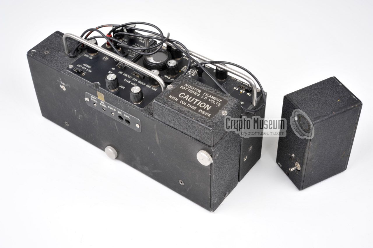
The A-2 could be expanded with the (optional) panorama viewer (S-1).
It is larger than the A-2 receiver itself, and is mounted to the
back of the receiver, by means of two large bolts,
so that it becomes one unit. The green phosphor screen
of the Cathode Ray Tube (CRT) is slightly sloped for bettery visibility
from the user's position.
The S-1 is connected to the A-2
and the LFB-1 (when used) by means
of three 'flying wires' with colour-coded mini jack plugs: black,
red and silver. The S-1 takes its power from the A-2, but has its
own batteries for the filament of the CRT.
|
|
|
Each of the six TLF-tuners has its own ferrite antenna mounted at
the top. In addition it is possible to connect a wire antenna directly
to the banana socket at the right side of the tuner.
A suitable piece of wire with a banana plug at one end,
wound onto a piece of carton, is supplied with the set.
|
|
|
|
|
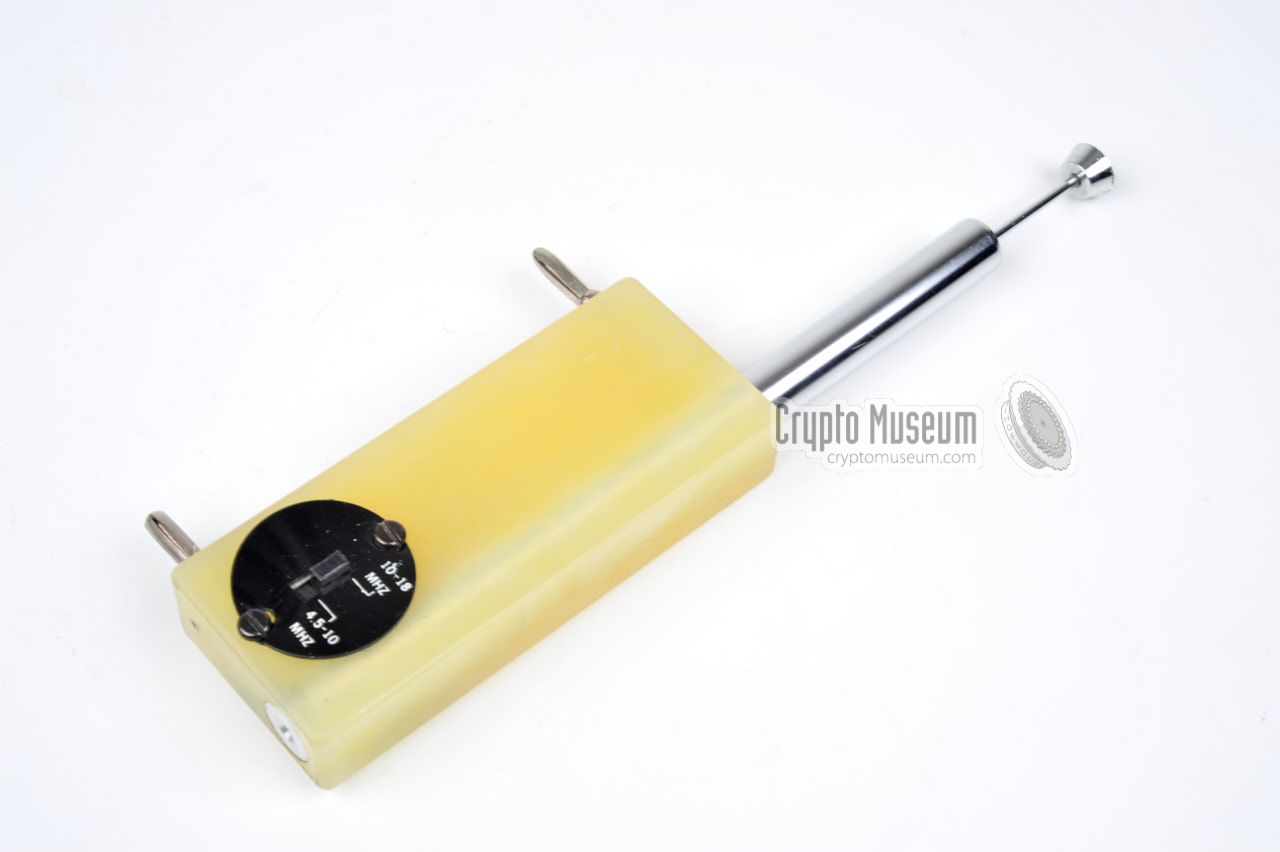
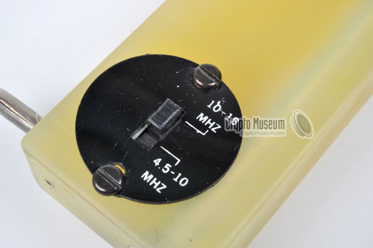
Telescopic antenna
4.5 - 18 MHz
|
|
|
For Short Wave (SW) frequencies between 4.5 and 18 MHz, a suitable
telescopic antenna is supplied with the set.
It can be inserted into the right side
of a T-18 tuner by means of two fixed banana plugs.
Note that this antenna is not suitable for any of the other tuners.
At the bottom of the antenna is a small switch for selection of the
required sub-band: eiter 4.5 - 10 MHz or 10 - 18 MHz.
|
|
|
|
|
Telescopic antenna
18 - 340 MHz
|
|
|
A similar telescopic antenna is supplied for the VHF/UHF
18 - 340 MHz range. It is nearly identical to the antenna
show above, but does not have the sub-band selector.
This antenna is suitable for the T-75 and T-340 tuners only.
It can be used in combination with the TLF-tuners, but with
limited effect.
|
|
|
|
|
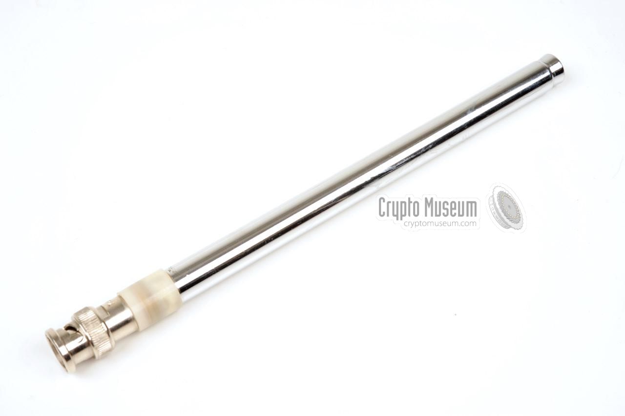
Telescopic antenna
> 340 MHz
|
|
|
The three tuners for the upper frequency ranges (T-650,
T-1200 and T-2000) are not equipped with banana sockets. Instead, they
have a BNC socket for connection of the antenna
shown in the image on the right, or an external antenna.
The antenna shown here is supplied with the set and is
suitable for all frequencies between 340 MHz and 2 GHz.
As a general rule of thumb, the lower the frequency, the
further the antenna should be extended.
|
|
|
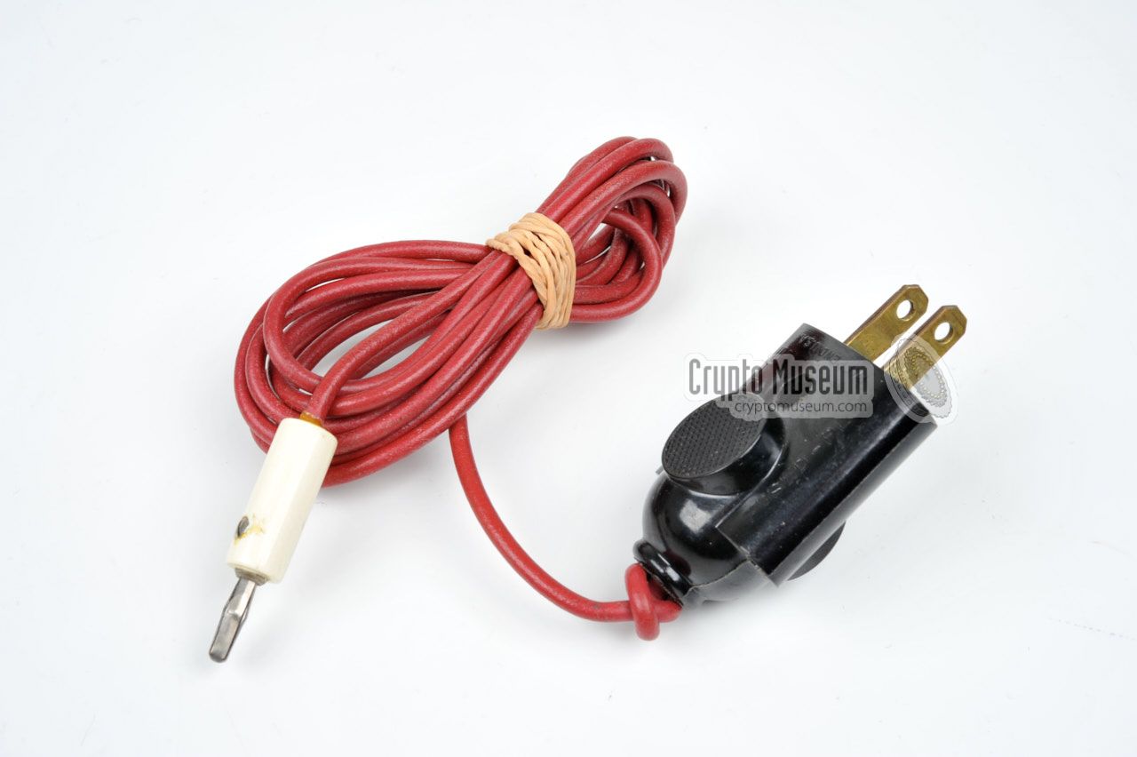
In addition to the antennas shown above, it was also possible to
use the wiring of the mains AC power network as an antenna.
A suitable mains plug/wire combination is supplied with the set.
This type of antenna is suitable for use in combination with the
TLF-tuners only. The banana plug should be connected to the lower
banana socket of the tuner.
|
|
|
|
|
Multi-wire cable for detached use
|
|
|
When using the TLF-tuners in a detached configuration,
this 50 cm piece of multi-wire cable should be used to connect
the TLF-tuner to the LFB-1 unit.
It allows the tuner to be held (and tuned) in the operator's
hand, whilst the receiver is attached to the operator's belt.
For concealed use, a special belt clip was available.
|
|
|
|
|
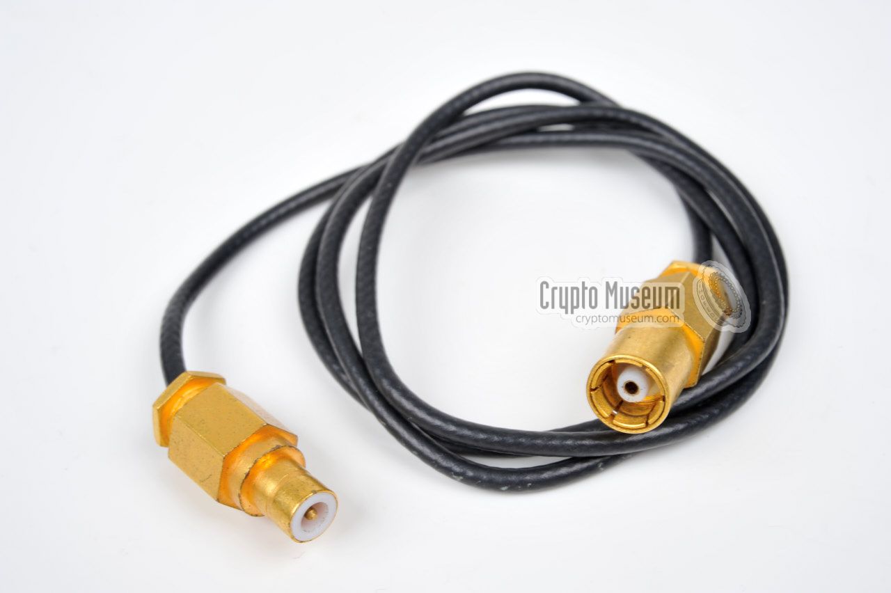
Coaxial cable for detached use
|
|
|
The six tuners for the higher frequencies (T) can also be
used in a detached configuration, by using the 60 cm coaxial
cable shown in the image on the right. It connects the
T-tuner directly to the A-2 Basic Unit.
It allows the tuner to be held (and tuned) in the operator's
hand, whilst the receiver is attached to the operator's belt.
For concealed use, a special belt clip was available.
|
|
|
The A-2 receiver delivers its demodulated audio (AF) to
a pair of 1000 Ohms headphones.
As the original headphones are currently missing from the A-2 set
featured on this page, we are not able to show them.
|
|
|
Device Portable modular intercept receiver Purpose Bug finding Manufacturer Mason Engineering Model A2 Year 1970 Country USA Frequency 2 kHz - 1200 MHz (2000 MHz on the later version) Sensitivity Better than 3µV for 10dB of (S+N)/N Modulation AM, FM, CW (other signals detected but not demodulated) Gain Sufficient to read-out thermal noise Audio 300 - 3000 Hz Panorama 3% of center frequency Power 1.5W (with all circuits on)
|
Circuits IF amplifiers, detectors, AF amplifier, S-meter, BFO, power Dimensions 143 x 102 x 46 mm Weight 3 lbs 136 grams IF frquency 23.5 MHz IF bandwidth 12 kHz, 90 kHz, 200 kHz (other bandwidths on special order) Audio 30 mW into 1000 Ω Inputs IF (50 Ω @ 23.5 MHz), external power Outputs Audio, -18V/DC, second detector, -12V/DC regulated
|
Nar 12 kHz (narrow) Med 100 kHz (medium) Wide 350 kHz
|
- Basic Unit (without tuner)
LFA-1 Audio amplifier, internal batteries and S-meter - IF strip (455 kHz), BFO, AM detector
- Tuners for the 2 kHz - 4.5 MHz range (see above)
- Tuners for the 4.5 MHz - 2 GHz range (see above)
- Accessories: case, antennas, wiring, headphones, tools, etc.
- Panorama Unit (display)
- External battery pack (optional) for 120 hour use
- Mains power supply (95-250V AC in, 18V DC out)
|
A-2 Basic Unit: 2 x Mallory TR137R @ 9.8V BP-3 Battery Pack: 14 x Mallory RM12R @ 1.35V (18.8V) S-1 Panorama Unit: 2 x Mallory RM12R @ 1.35V (parallel) LFA Audio Amplifier S-Meter: 5 x Mallory TR133R @ 4.05V
|
A-2 Initial version (up to serial number 621) A-2B Serial number 621 and higher 1 A-2C With subcarrier option (only 64 ever made) A-2C-S All-in-one unit
|
-
Electrically and operationally, the A2-B is identical to the A-2.
The only differences are the use of different connectors on the tuning
units and the use of different transistors in some circuits.
As a result, the modules of the A-2B are not interchangeable
with those supplied with the earlier A-2.
|
-
Document kindly supplied by Immo Hahn [4].
|
- Personal correspondence with a former Mason employee
Crypto Museum. January 2009.
- Granite Island Group, Used equipment price index list
Retrieved January 2009.
- Kevin D. Murray, Mason Enigineering Model A-2CS, etc.
Forum discussion on spybusters.com. 16 Jan 2005.
- Immo Hahn, A-2 Short German user manual - THANKS !
Created by the Swiss PTT. See above under [B]. 10 May 2012.
- Wikipedia, Phosphor
Retrieved May 2012.
|
|
|
|
Any links shown in red are currently unavailable.
If you like the information on this website, why not make a donation?
© Crypto Museum. Created: Thursday 29 October 2009. Last changed: Wednesday, 05 November 2025 - 12:00 CET.
|
|

|
|
|