|
|
|
|
|

|
RDF Receiver WL-53400
Tester WL.53400 was the official name of a compact portable
radio direction finder (RDF) that
was intended for intercepting and locating clandestine transmitters
operating on British territory. The receiver was developed around 1939 by
the Wireless Branch (W. Branch) of the General Post Office
(GPO, now British Telecom, or BT)
at Dollis Hill (UK), and is commonly known as the GPO-receiver.
|
The receiver was developed and built by the GPO and was used intensively
during and after WWII. It is housed in a Bakelite enclosure and is fully
self-contained.
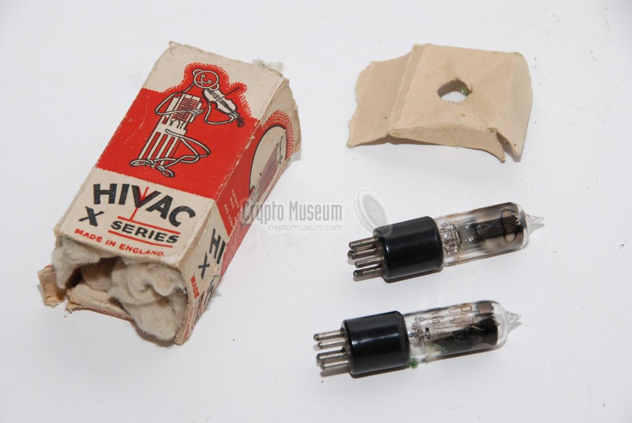
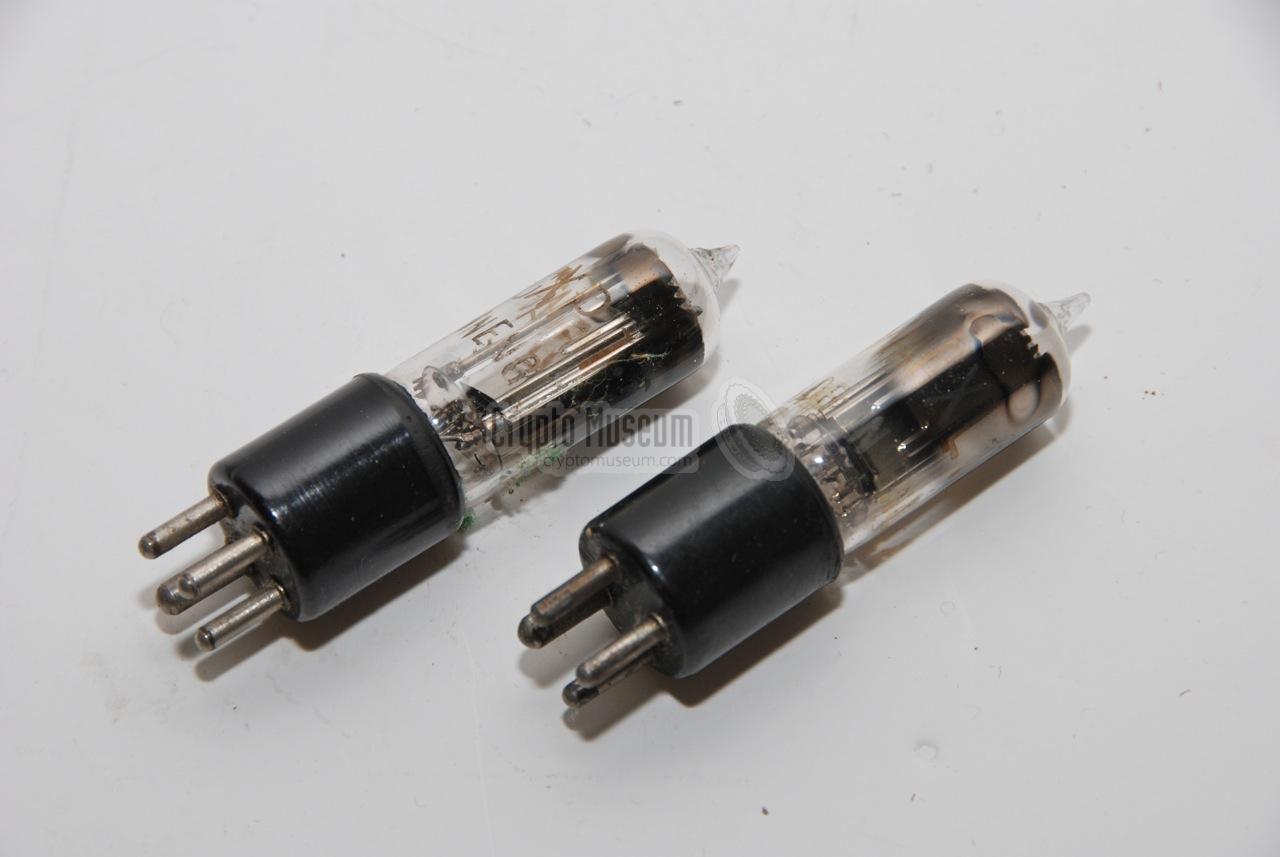
The circuit is built around just two HIVAC 1.5V miniature valves (tubes).
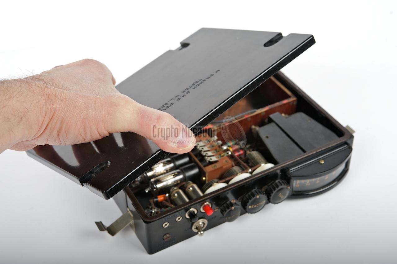
The most special feature of this receiver is the fact that the top lid of
the bakelite case, acts as the frequency range selector (plug-in), but also
as the direction-finding (DF) loop antenna.
The image on the right shows a typical GPO receiver, with lid number 10 in
place. The controls, read-out and connections are all at the front.
|
|
|
Only a small number of GPO receivers were ever produced at Dollis Hill,
as a result of which they are now desired collector's items.
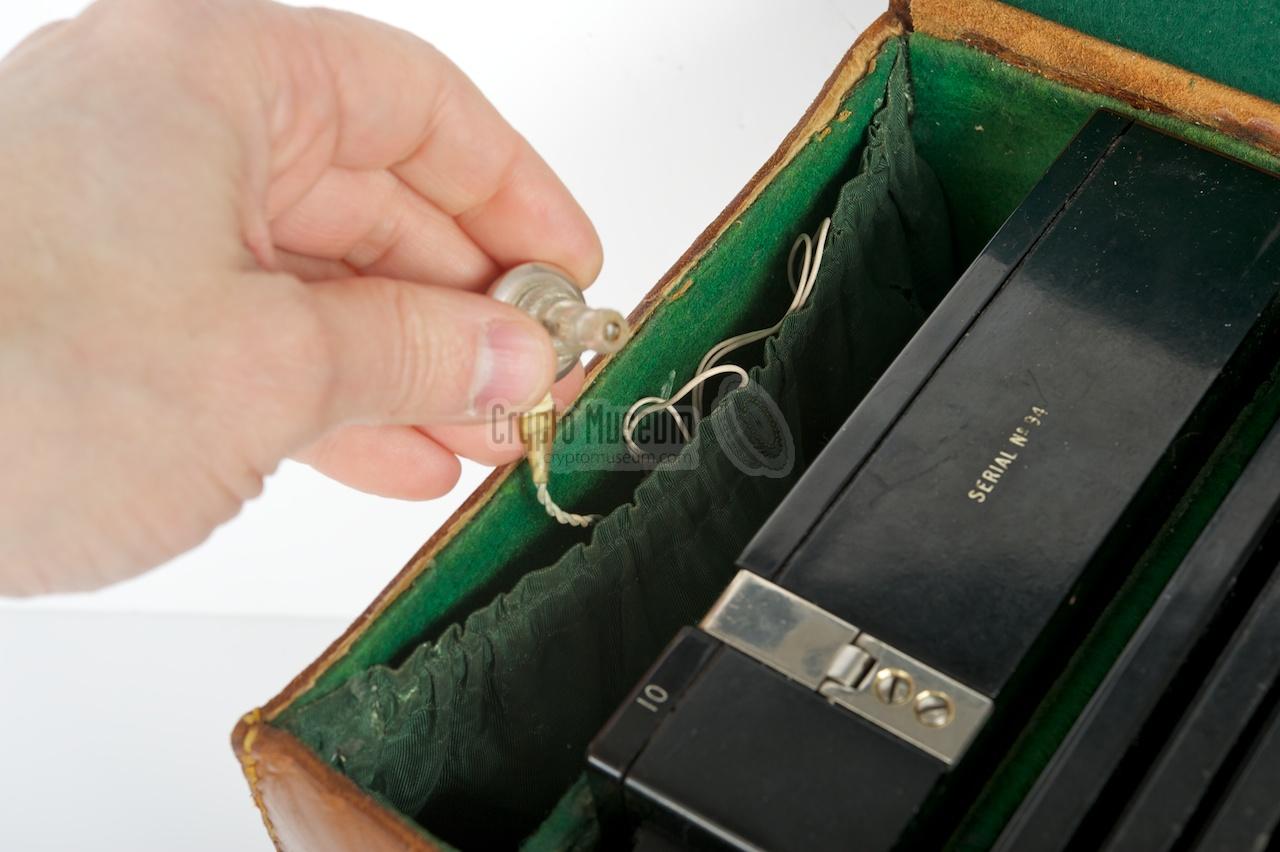
The unit shown here has serial
number 94 and was part of the 1st batch of 100 units that were produced
in 1939.
After WWII, it was used by the Department of
Trade and Industry (DTI) to locate Cold War related and clandestine transmitters and 'pirates'.
The receiver is also described in Louis Meulstee's Wireless for the Warrier -
Part 4 [1], but his description is somewhat different from our device.
First of all there are 10 frequency-range coils (lids) rather than 9.
Secondly, our own GPO receiver has two different valves (HIVAC XL and XP),
rather than two identical ones (XP).
The XL valve was made especially for LF applications.
|
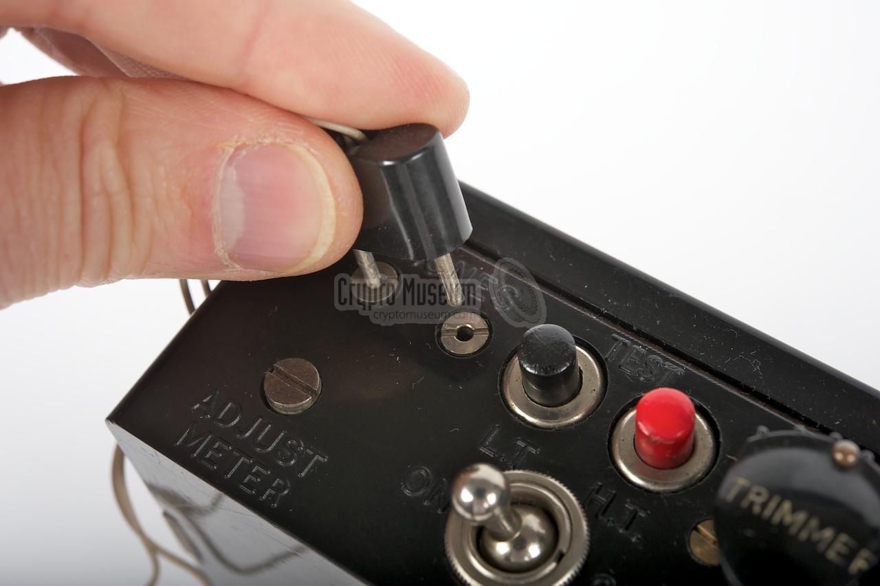
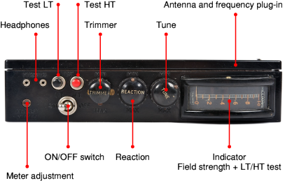
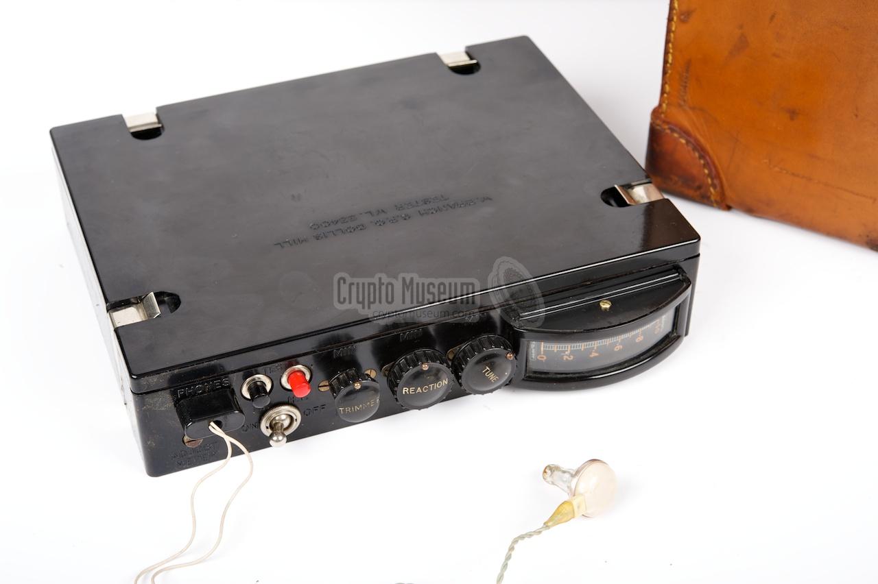
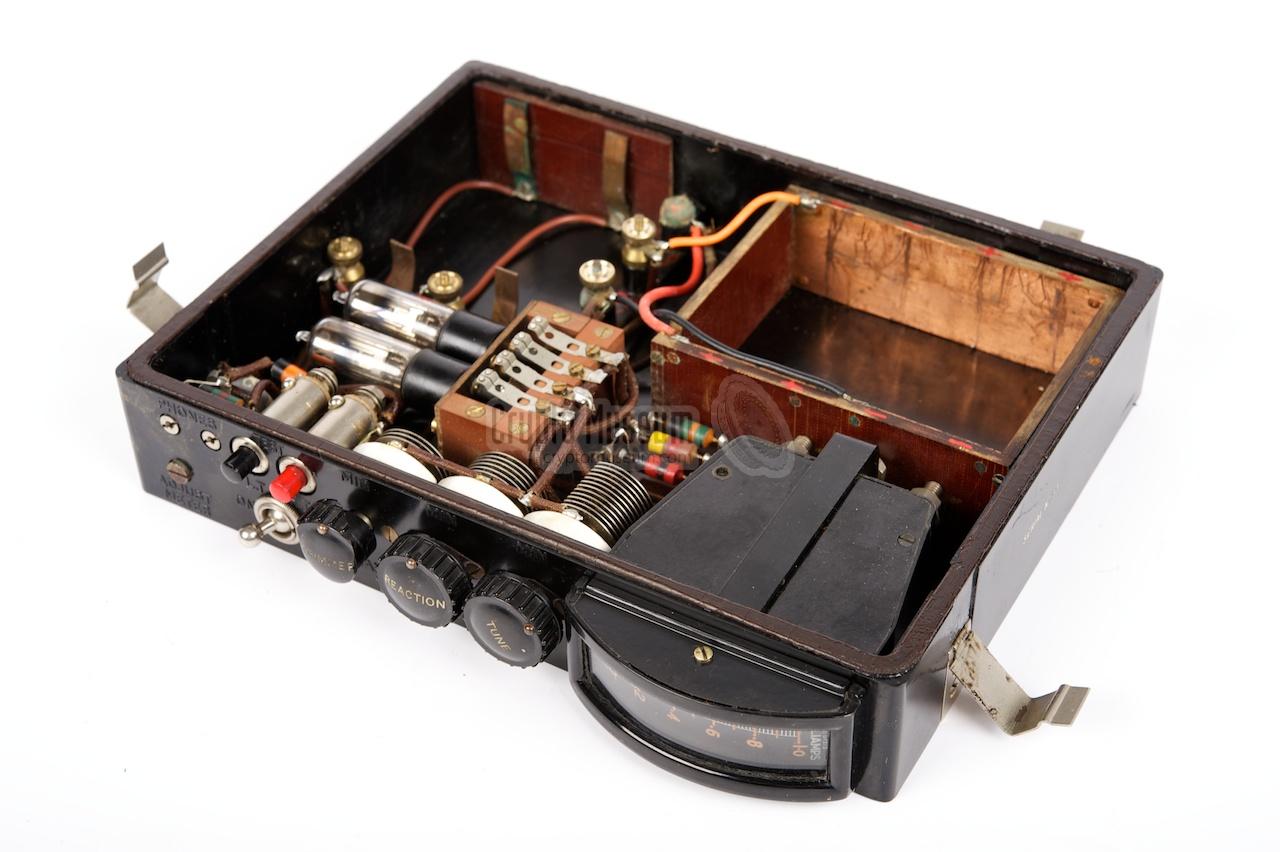
The GPO receiver is a very compact device that has all controls and
connections nicely aligned at the front panel. The unit is powered
by internal LT and HT batteries, and is turned on by
flipping the metal ON/OFF switch to the left. A pair of headphones
or an earpiece should be connected to the two sockets at the top left.
When in operation, the large meter at the right is used as a field-strength
indicator. When operating the black and red push-buttons (above the
ON/OFF switch), the meter is used for checking the LT and HT voltages,
which are 1.5V and 30V DC respectively.
A suitable coil lid (i.e. frequency plug-in) should be clipped
on top of the receiver before switching it on. The receiver can
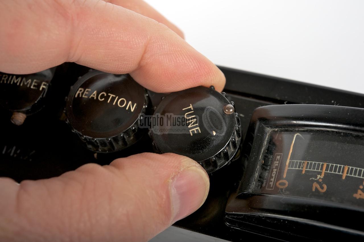
be used in oscillating and non-oscillating mode, with the REACTION
knob controlling the level of self-oscillation. Tuning into a
station is best done with the receiver oscillating. The case can
then be rotated in the horizontal pane in order to find the maximum
signal strength. When homing in on the signal the sensitively of
the receiver can be reduced by turning the REACTION knob to the MIN
position. If the signal is still too strong, the 'meter adjustment'
screw at the botton left can be used to further reduce the sensitivity.
When in close proximity of a (strong) radio station, it might not be
possible to reduce the sensitivity enough to get a useful reading
on the meter. In such cases it is best to search for the minimum field
strength when rotating the receiver, rather than the maximum.
|
|
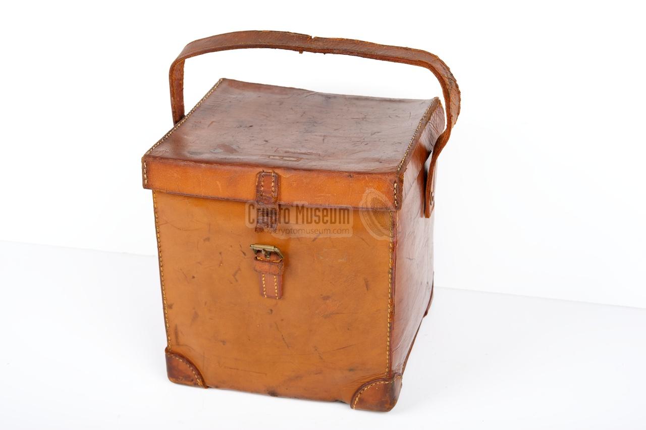
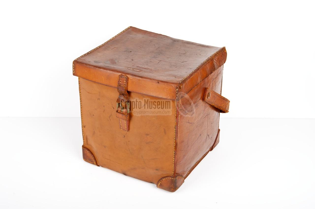
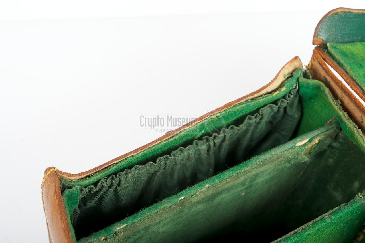
When unused, the GPO-receiver, the frequency modules and the accessories
were stored in a qubic leather transit case. The case has three compartments:
(1) headphones and spares, (2) the receiver with one frequency module (lid)
and (3) the remaining 9 frequency modules.
|
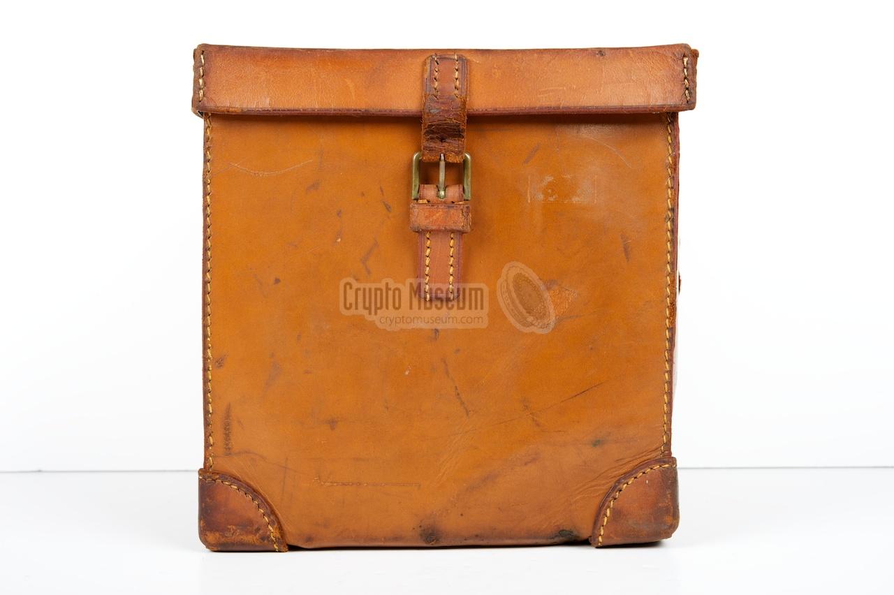
The image on the right shows a typical war-time leather storage case that
roughly measures 23 x 21 x 23 cm. It has a leather strap that allows the case
to be carried around by hand, and a smaller strap with a buckle to keep the
top lid closed. The corners at the bottom of the case
have been strengthened with extra thick leather.
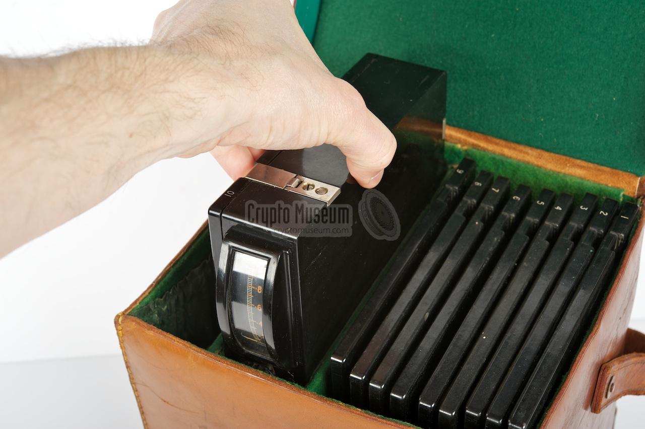
Inside the case are three compartments. A narrow one at the left where the
headphones and the spare valves are stored, a slightly larger compartment
where the actual receiver is stored (complete with one frequency plug-in)
and the largest area that holds the remaining nine frequency coils.
The interior is coated with dark green felt, except for the receiver's
space which is coated with green velvet to avoid scratches.
The case shown here has seen quite some action. After its war-time use,
it served with the DTI (UK), that was mandated for locating and
charging clandestine radio stations. Initially, such stations were Cold War
spies operating on British territory, but later the attention shifted to
'pirate' stations. Once the receiver was replaced with more modern equipment
in the early 1960s, it was dusting away on a shelf in a damp shed where it sat for more
than 40 years.
|
|
|
|
When the receiver was rediscovered in 2011,
the case was in deteriorating state.
Much of the leather had dried out and parts of it had desintegrated
completely. Part of the felt on the inside had become infected with fungus
and pieces of the interior coating had come off.
However, with a bit of patience and some old fabrics, the case was restored
to much of its former glory.
|
|
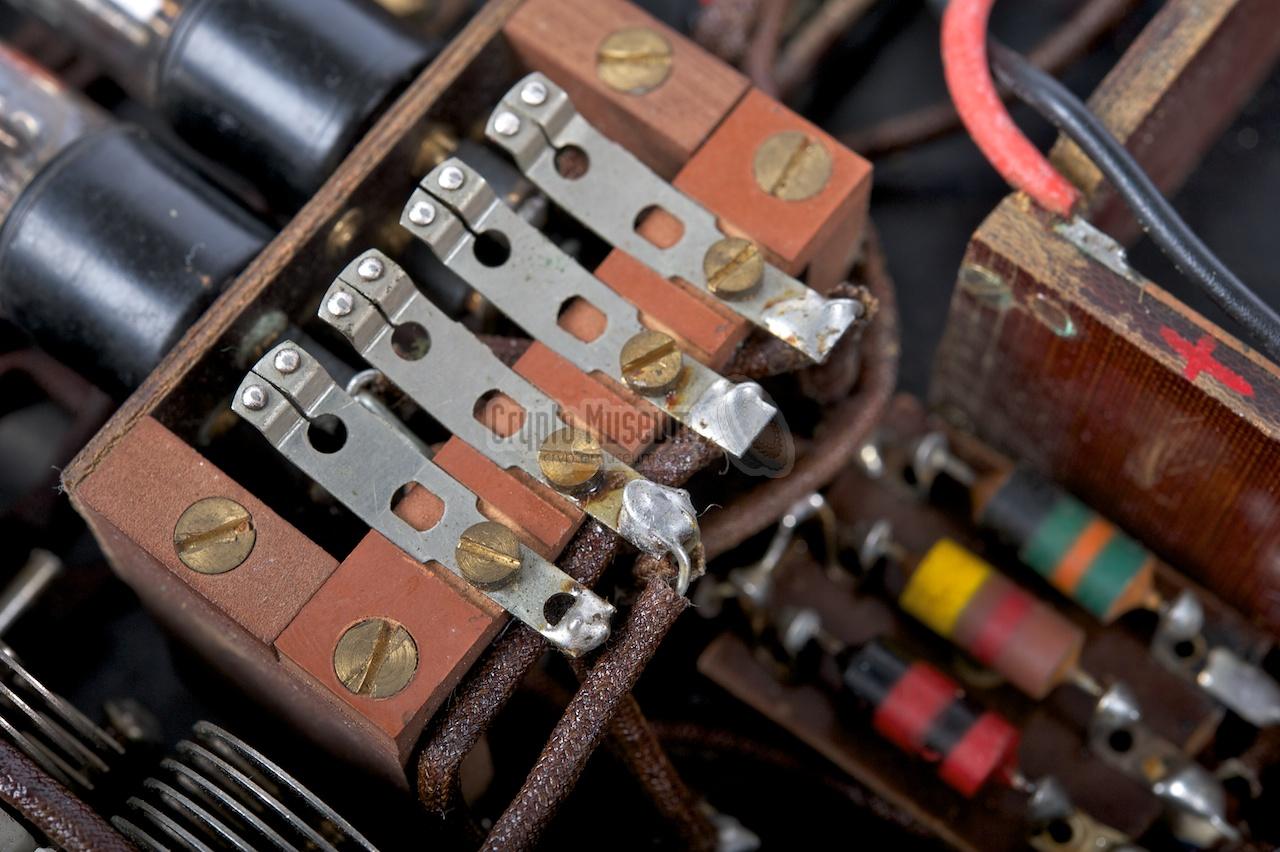
The receiver covers all frequencies between 150 kHz and 28 MHz, divided
over 10 ranges. For each range, a separate coil (top lid) is
supplied. Each coil has four in-line contacts
that mate with
four spring-contacts in the receiver.
The lid is held in place by four metal clips that are positioned asymmetrically
in order to prevent the lid from being mounted the wrong way around.
|
The following ranges are available:
- 150 - 230 kHz
- 230 - 360 kHz
- 360 - 600 kHz
- 600 kHz - 1 MHz
- 1 - 1.6 MHz
- 1.6 - 2.7 MHz
- 2.7 - 4.6 MHz
- 4.6 - 9 MHz
- 9 - 16 MHz
- 16 - 28 MHz
|
|
|
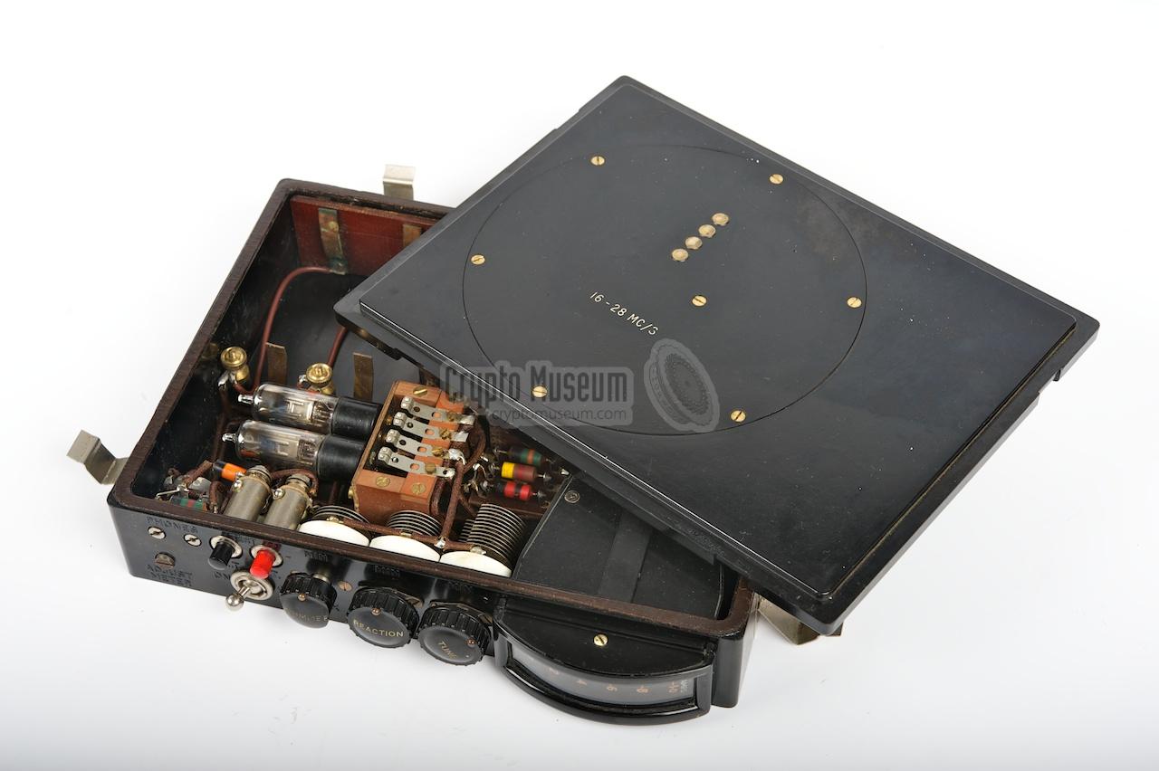
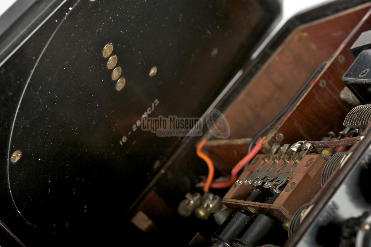
The image above shows the GPO Receiver with lid number 10 (16-28 MHz)
lying on top of it (upside down). De lid is rectangular and has a circular
hollow space inside it, in which the actual
frequency coil is located.
The coil can be opened by removing the 7 bolts
that keep it in place.
|
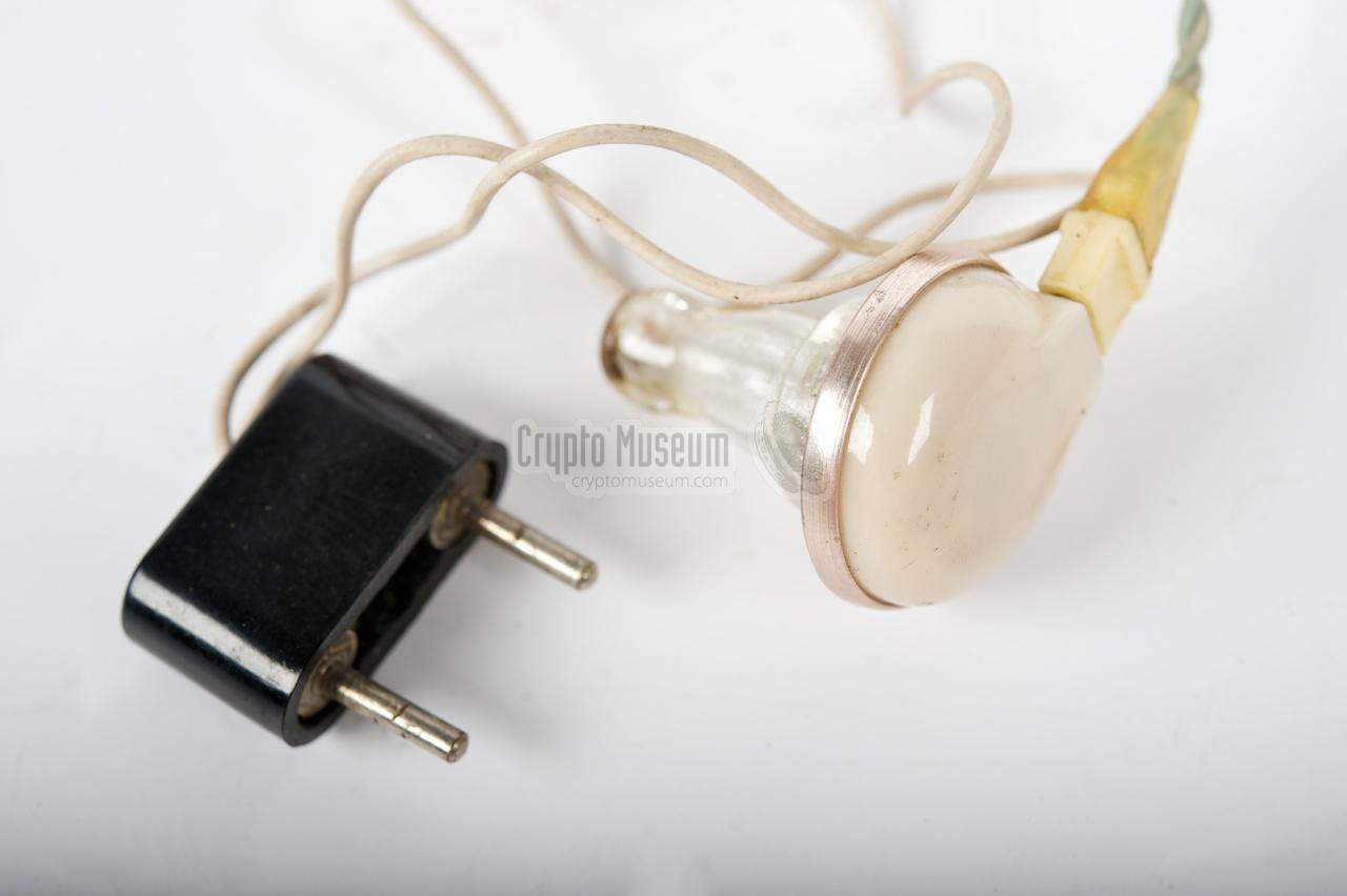
The GPO receiver has a high-impedance audio output. It was used in
combination with a high-impedance headset
or with crystal earphones, such as the one shown here.
It is connected to the receiver's PHONES-socket by means of the 2-pin
plug shown in the picture.
Although the unit was originally supplied with a pair of black
headphones, crystal earphones were often preferred as they could be worn
inconspicuously.
|
|
|
|
The GPO Tester WL.53400 is a beautifully built simple receiver that can be used
in the near field of a (clandestine) transmitter. Its electronic circuit
constists of only two minuature valves, made by UK manufacturer HIVAC.
According to [1], both valves are identical (XP), but in our sample we found
two different ones (XP and XL). Furthermore, one of each is supplied as spares
with this receiver. It is therefore possible that a HIVAC XL was used for the
LF amplifier.
|
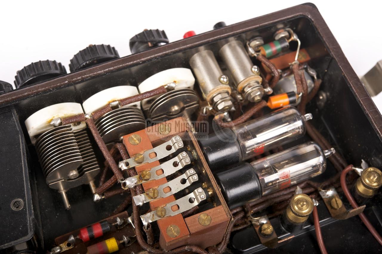
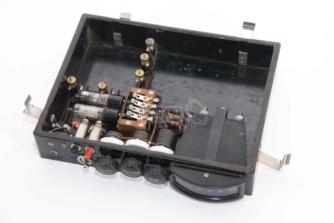
The image on the right gives a clear view at all the electronics that are
present inside the box. At the center are the two minature valves and the
four spring-contacts for the frequency coil. At the left are three
adjustable capacitors.
Below the visible items, at the bottom of the case, are only a couple of
passive components (resitors and capacitors). The rest of the case is filled
with the indicator and the batteries. The indicator is a mA-meter that is
also used for testing the LT and HT voltages. This is done by pressing the
black and red buttons at the front.
|
|
|
|
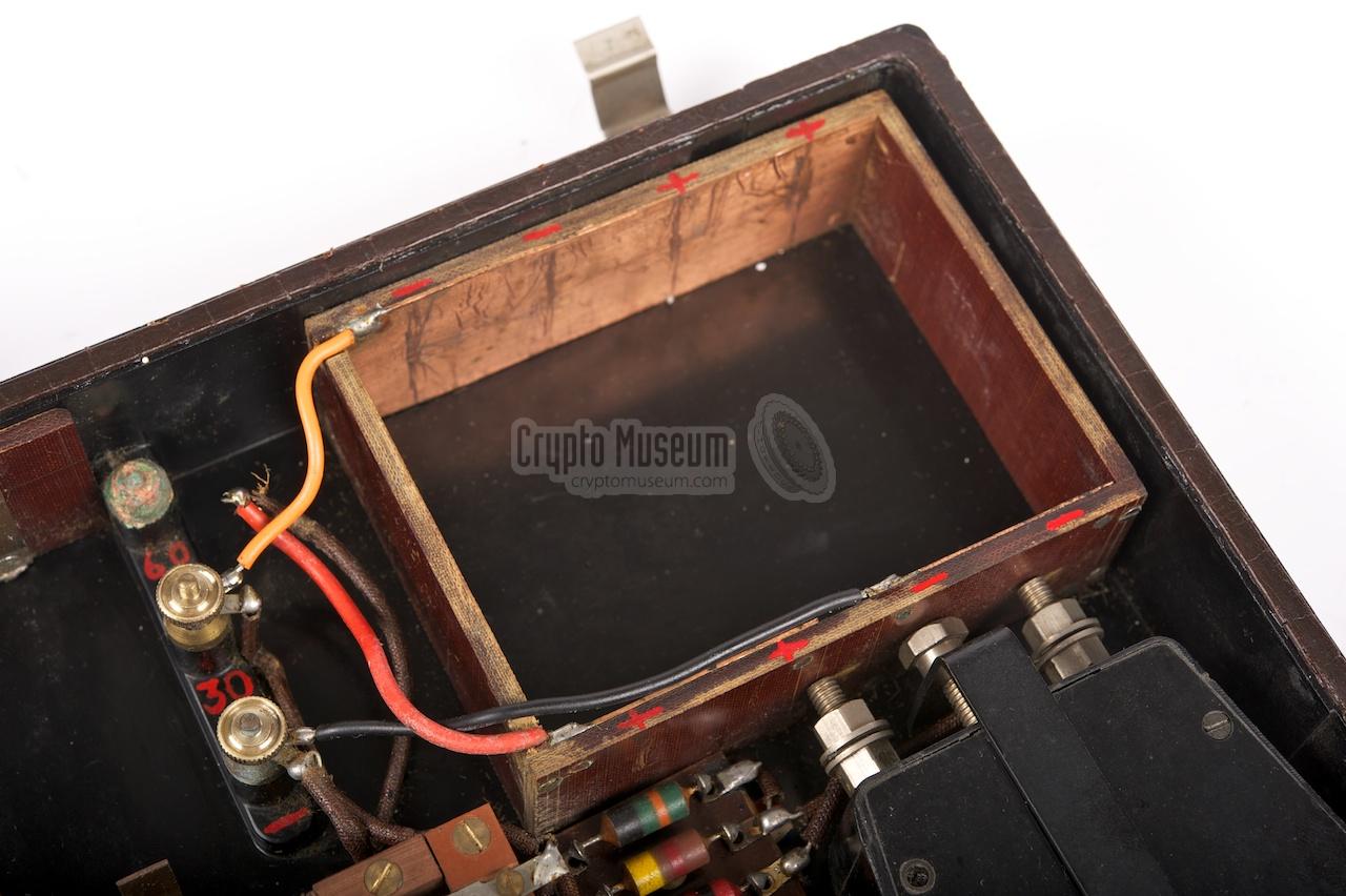
Apparently our unit was modified at some point during its lifetime.
Traces inside the case reveal that leaking batteries have caused problems
in the past. The original batteries (LT 1.5V and HT 30/60V) were installed
in two empty spaces
inside the case [2].
In the modified version [3],
two battery holders (made of pertinax) are installed.
A separate 1.5V battery is used
for the filament of each valve, whilst two 30V batteries are connected in
series to produce 30V and 60V HT.
|
The circuit diagram below was sent to us in November 2013 [A]
and clearly shows the operation of the receiver. It consists of
a tuned reacting detector (V1) followed by a DC amplifier (V2).
The set is tuned by means of two adjustable capacitors: one
marked TUNE (C2) for selecting one of five 'click-in' tuning ranges,
and a separate one marked TRIMMER (C3) for fine tuning.
A separate capacitor marked REACTION (C1) controls the level of
feedback or self-oscillation. It is used to control the sensitivity
of the receiver. This adjustment has 24 click-in positions.
Potentiometer P1 at the top right can be used to further reduce
the sensitivity when in close proximity of a transmitter.
The second stage (V2) amplifies the detected signal to headphones
level and also controls the reading of the field-strength meter.
For testing the condition of the batteries, two switches, S1 and
S2, can be used to measure the LT and HT voltages respectively.
The measuring circuit is dimensioned in such as way that LT Test (S1)
produces a full-scale reading at 1.5V, whilst HT Test (S2) gives a
full-scale reading at 30V (i.e. 1 mA on the scale).
|
R1 50K R2 5K R3 100K R4 10M R6 1450 Ohm R7 30K
|
P1 50K C1 50p C2 100p C3 25p C4 100p X 2K (earpiece)
|
V1 Hivac XL V2 Hivac XP M1 Meter 0-1 mA S1-2 Button switch S3 Toggle switch
|
81 Royal Signal Museum 94 Crypto Museum 100 Private collector 203 Crypto Museum
|
- Louis Meulstee, RDF Receiver GPO
Wireless for the Warrior. Part 4. September 2004. ISBN 0952063-36-0.
➤ Vol. 4 Amendment No. 2 (version 1.0) with clean circuit diagram
- Cor Moerman, GPO Receiver with serial number 203 - THANKS !
Part of the exhibition Secret Messages
in November 2008.
Crypto Museum, November 2008 — November 2020.
- Crypto Museum, GPO Receiver with serial number 94
Modified battery compartment. Crypto Museum, March 2012.
|
|
|
|
Any links shown in red are currently unavailable.
If you like the information on this website, why not make a donation?
© Crypto Museum. Created: Saturday 17 March 2012. Last changed: Monday, 30 November 2020 - 10:53 CET.
|
 |

|
|
|


![GPO Tester WL.53400 circuit diagram [A]](img/gpo_circuit.jpg)