|
|
|
|
|

|
|
UK Phone Voice Scrambler GPO No. 6AC → ← No. 6B
|
|
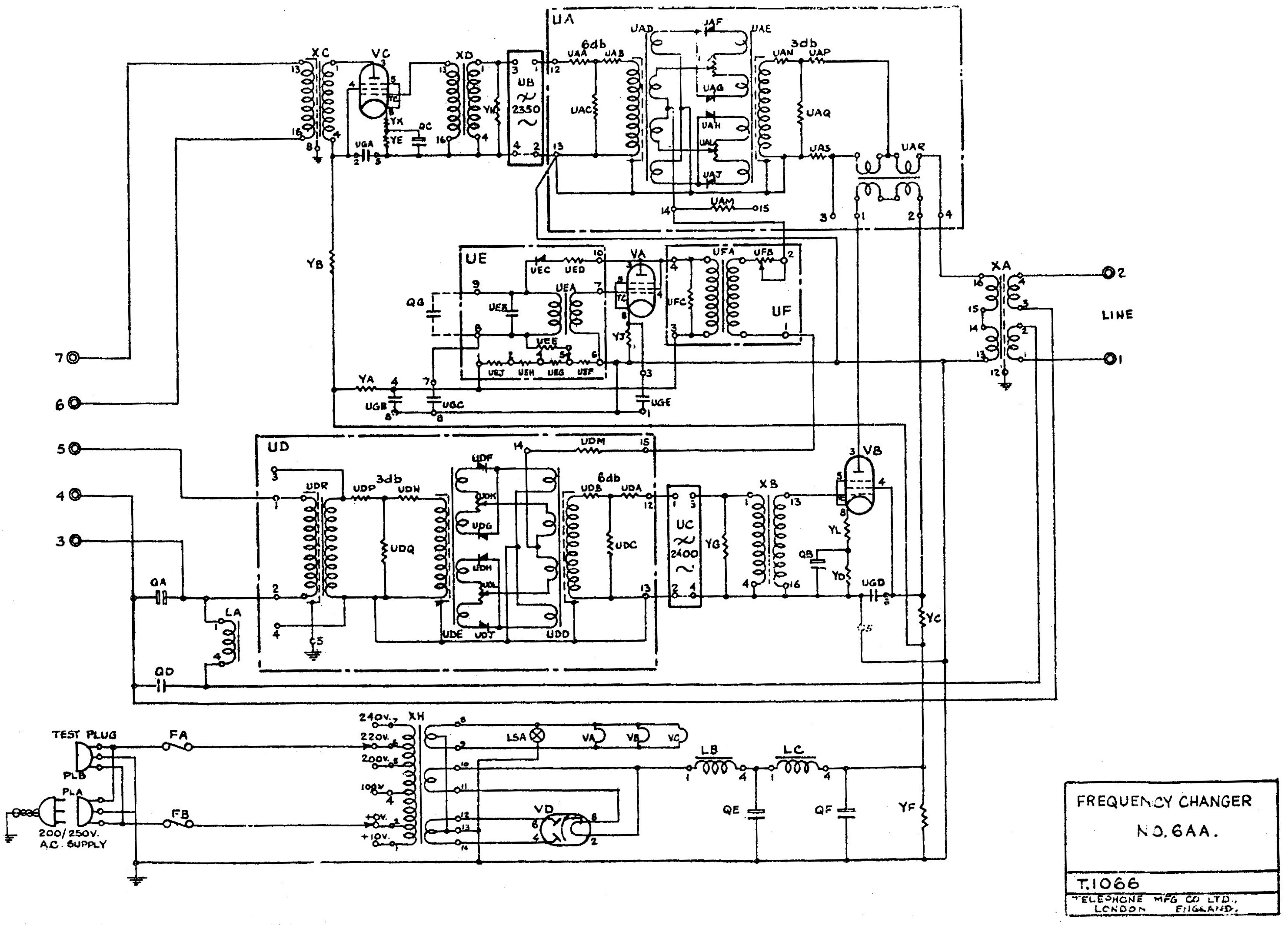
Frequency Changer No. 6AA
|
|
|
|
Telephone scrambler · 1942-1944
- not in collection
|
Model 6AA came in two flavours: 6AA/0 and 6AA/1, differing only in their
power supplies.
The 6AA/0 was suitable for the 200-250V AC mains, which was used
in most parts of the UK.
The 6AA/1 was more flexible and
could be powered from the 100-110V AC or 200-250V AC mains.
This made the 6AA/1 suitable for use in areas that still had a 110V AC
network.
The 6AA was the first Frequency Changer to be housed in a metal enclosure.
The image on the right shows a typical 6AA unit with its
hinged top lid open, giving a good view of the valves.
|
|
|
For use on Direct Current (DC) networks in the UK, the SA-6023
DC/AC converter was available separately [D]. It was connected between the
DC mains network and the power input of the 6AA unit.
Frequency Changer No. 6AA was introduced in 1942 and was built by both
GPO and TMC until 1944 when it was succeeded by the improved
Frequency Changer 6AC. The latter offers a wider range of power options
— including 12V DC — and an improved receiver circuit [C].
➤ Circuit diagram
|
Within the British Corps of Royal Electrical and Mechanical Engineers (REME),
a complete setup, consisting of Frequency Changer 6AC/3, a matching telephone set,
a junction box and suitable wiring, was known as Privacy Equipment No. 1 - Mark I.
It was described in February 1945 in a series of Electrical and Mechanical
Engineering Regulations (EMERs), such as EMER T 710/1 [3].
➤ Privacy Equipment No. 1
|
Below is the block diagram of Frequency Changer 6AA.
At the far right is the 2-wire subscriber line, which is usually connected
in parallel to a regular telephone set with a dial. At the far left is
the handset of the voice terminal. The audio signal from the microphone is
applied directly to a ring mixer (UD), where it is added to the 2500 Hz
signal from the central oscillator (VA).
At the output of the mixer, the sum
and the difference
of the two signals are available, with the difference being the
mirrored version of the original signal (here shown in red).
This means that low-frequency tones have become high-frequency
tones and vice versa.
After low-pass filtering (UC), only the mirrored
signal remains, which is then amplified (VB) and delivered to the line.
The bottom half of the diagram shows the reception path, which is
more or less the same, but in reverse direction. The mixer (UA)
produces two images, of which the lower one is the mirrored
version of the received signal. After filtering (UB), it is amplified (VC),
so that only the lower part remains (blue).
This is a copy of the original audio signal.
The spectrum diagrams illustrate what happens.
The inverted (scrambled) audio is shown in red.
Note that this only works, of course, when both parties use the same
inversion frequency of 2500 Hz.
It is also important that the two low-pass filters (UB and UC)
are of a higher order and have a sharp cut-off. This means that
the baseband (everything up to the crossover frequency) is passed
unattenuated, and that everything above its crossover frequency
is sufficiently suppressed. Together with the ring mixers, the
low-pass filters are responsible for the overall audio quality.
Note that filter UB in the reception path is placed between the
the mixer (UA) and the amplifier (VC), whilst in the 6AC successor
it is placed between the amplifier (VC) and the speaker.
|
The CV1052 is an indirectly heated pentode, introduced in 1940 for use in
audio circuits. Apart from AC and DC applications, it was also used in car
audio systems, either as a class 'A' amplifier or in push-pull configuration.
It is equivalent to the EL32. It is also electrically
(but not physically) equivalent to the EL2.
It was one of the standard valves of the UK's
General Post Office (GPO).
➤ CV1052 datasheet
|
Device Voice scrambler Purpose Privacy over telephone lines Years 1942 - 1944 Principle Audio band frequency inversion Manufacturer GPO, TMC Model Frequency Changer 6AA/0, 6AA/1 Predecessor Frequency Changer 6 Successor Frequency Changer 6AC Pivot freq. 2500 Hz Remote 2-wire telephone line, 600Ω (default or 300Ω (option) Local 4-wire interface (handset) Circuits Oscillator, amplifier (2x), mixer (2x) Valves 3 x CV1052 (EL32), 1 x 5ZVG (rectifier) Mains 6AA/0: 100-110V AC
6AA/1: 100-110V AC200-250V AC Dimensions 585 x 360 x 185 mm Weight 41 kg
|
6AA/0 200-250V AC 6AA/1 100-110V AC, 200-250V AC
|
-
Document kindly provided by Louis Meulstee [2].
|
|
|
|
Any links shown in red are currently unavailable.
If you like the information on this website, why not make a donation?
© Crypto Museum. Created: Wednesday 26 May 2021. Last changed: Sunday, 19 November 2023 - 13:57 CET.
|
 |

|
|
|


![Frequency Changer 6AA. Photograph kindly provided by Andy Grant [1]](img/fc6aa.jpg)

