|
|
|
|
|

|
|
Mixer OTT UK Rockex →
One-time tape cipher machine
Noreen was a small portable off-line one-time tape
(OTT) cipher machine,
developed in the UK
in the early 1960's and used for diplomatic traffic
by the British Commonwealth 1 as a replacement for (or complementary to) the
Rockex cipher machine from
WWII, with which it was compatible.
The machine is also known as BID/590
(with variants
like the BID/590/2) 2
and as Mk-854M.
|
Noreen is compatible with Rockex,
a WWII
valve-based online/offline cipher machine
that was introduced in 1943. It uses the same
6-level keystream tapes,
but contrary to Rockex, Noreen can not produce
its output directly on punched paper. Instead, the encrypted (or decrypted)
text is printed onto a pre-gummed 9.4 mm paper strip by a
rotary printer just behind the keyboard.
The paper strips were then glued onto blank paper sheets
and re-typed on a regular teleprinter.
Noreen was introduced in the early 1960's in the UK, where it was
was used by the Foreign and Commonwealth Office (FCO).
By special arrangement, the technology was shared with Canada, where it was
used by the Office of External Affairs (now: Foreign Affairs).
The machine was also used by Australia and New Zealand,
but only for confidential communication with the UK [3].
The machine was initally marked as secret and confidential.
Althoug this is generally the case with cryptographic equipment,
mixing machines were commonly unclassified devices as they
do not contain any secret circuitry. With most other
mixers,
it was the combination of the machine
and a secret classified
keystream tape that
had to be treated as confidential.
Noreen entered service in 1962/63 and was used until the early 1980's.
The machine has since been declassified.
|
 |
-
In this context, the expression 'British Commonwealth' is used to
identify the following countries of the Commonwealth of Nations:
Great Britain, Canada, Australia and New Zealand.
-
BID means British Inter Departmental. Systems with a BID designator are
generally used by more than one single governmental agency or department.
➤ More
|
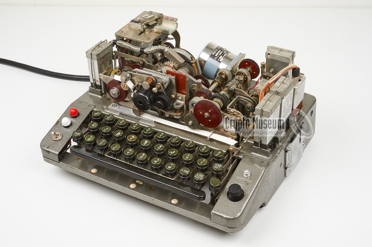
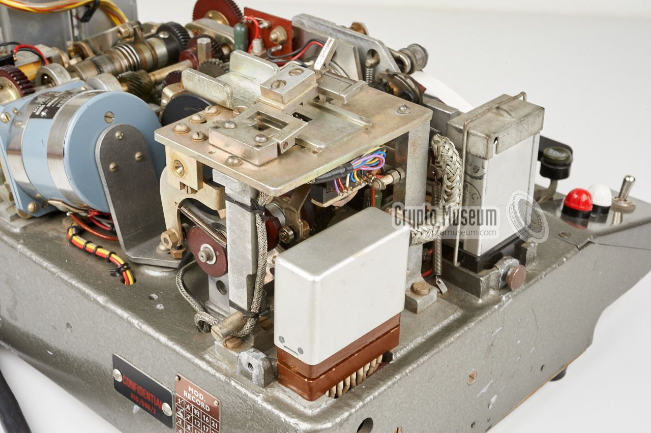
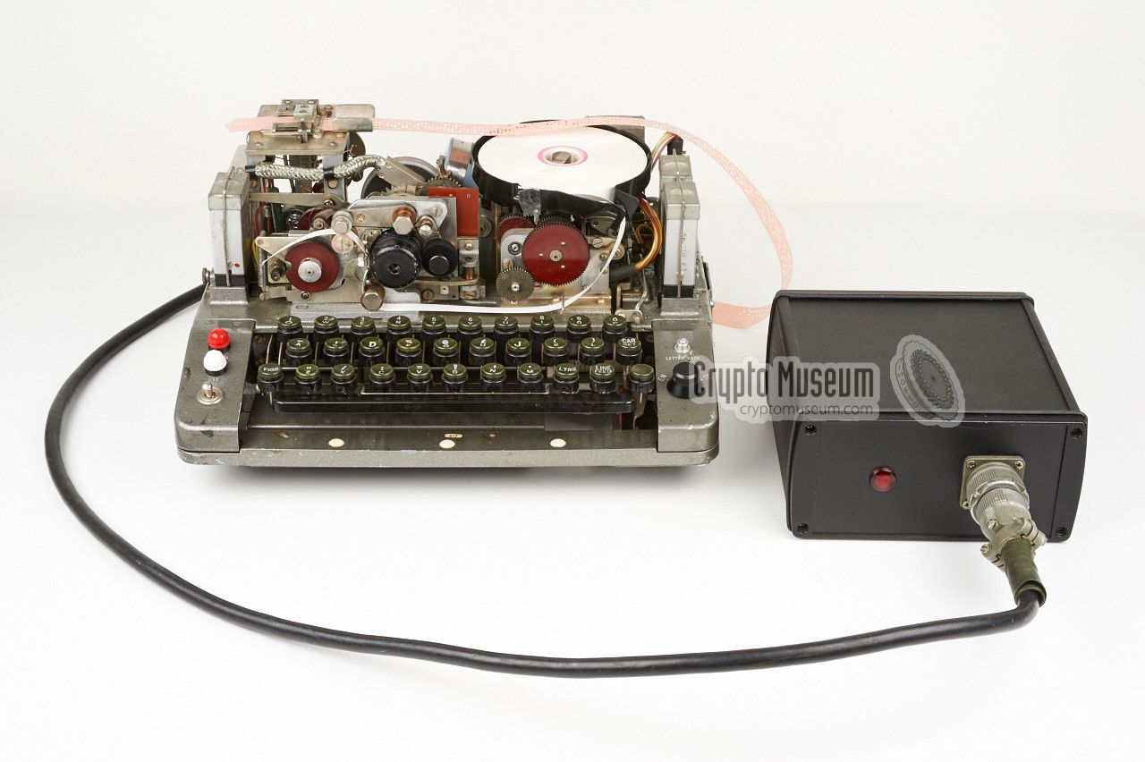
Noreen roughly consists of three sections: the keyboard
at the front,
a mechanical section at the rear (mounted on a die-cast chassis)
and the transistor-based electronic circuits at the bottom.
The diagram below shows the machine after the dust cover has been removed.
The circular black paper tray has been made partly transparent here,
so that you can see what is behind it.
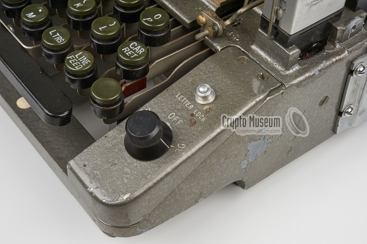
The machine is switched
ON by connecting a suitable battery pack
or PSU and placing the MODE selector at the
front right in the EN position for
encoding or to DE for decoding.
It can also be used for typing and printing plaintext,
by placing the MODE selector
in the OFF position.
An external paper tape feeder is normally attached to the right side.
It supplies the keystream tape
to the 6-channel tape reader
at the left rear.
When starting a (de)coding session, the tape should be placed at the first
character of the cipher block (i.e. the first character of the message
indicator on the keystream tape. The operator then enters the first
character of the message.
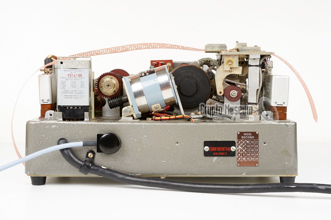
Noreen has only two physical connections
which are both located at the rear.
A fixed multi-wire black cable with a
10-pin connector at the end is used
to connect the machine to a special TEMPEST approved battery unit.
Furthermore, a 3-pin Bulgin socket is present for connection of the
tape sensing switch on the external paper tape feeder
(not shown here).
This sensing switch was used to detect whether a
keystream tape
for encoding or decoding was present in the feeder.
|
- BID/590
Initial version of Noreen. Introduced around 1962.
Modified several times during its lifetime, for example with TEMPEST
improvements.
- BID/590/1
Differences with BID/590 currently unknown.
- BID/590/2
Improved version with character counter mounted under the keyboard.
Introduced around 1969.
Modified 11 times during its lifetime.
This is the machine featured on this page.
- BID/591
Noreen instruction manual.
|
Noreen has a built-in tape reader at the top left.
This tape reader is used for the so-called keystream tape :
a punched paper tape that is filled with random characters A-Z. As the
international teleprinter alphabet (ITA2)
is based on 5-bit data, one would expect a 5-level tape reader in this position,
but this is not the case. Noreen's
keytape reader
expects a 7/8" wide paper tape, with 6-bit data. This means that a rather
uncommon format was used for the keystream tape.
In the image above, the two tape formats are compared. At the right
is a common 5-level teleprinter tape (blue).
The one on the left is the Rockex/Noreen key tape (red)
which has an unusual width and was probably custom made.
It is seen from the front/top of the machine.
Note that the extra tape channel (6) was added before channel 1 and that
a margin was added at the side of channel 5, probably to prevent the
tape from being inserted the wrong way around.
The keystream tape contains a random character data stream in the usual
5-level teleprinter format. This 5-bit information is mixed with the data
from the keyboard. Whenever a hole is present in channel 6 however,
the data is not enciphered but is sent directly to the printer.
This way a space can be inserted in the printed text after each 5th character,
while a double space was inserted after each 5th group. Channel 6 was
also used to automatically insert the (unencrypted) 5-letter message indicator
that marked the beginning of each section of 49 five-letter groups.
The keystream tapes were compatible with those of the
Rockex cipher machine,
and were created by means of a so-called paragrapher device. This device
punched random A-Z letters on the paper tape in blocks of 50 groups of 5 letters each.
The first 5-letter group was the actual message indicator which was not
encrypted.
This was done by punching the 6th hole in the key tape. The indicator
group was followed by 49 encoded 5-letter groups. Each group was separated
by a single space (again, using the 6th hole) with a double space after
each 5th group [1].
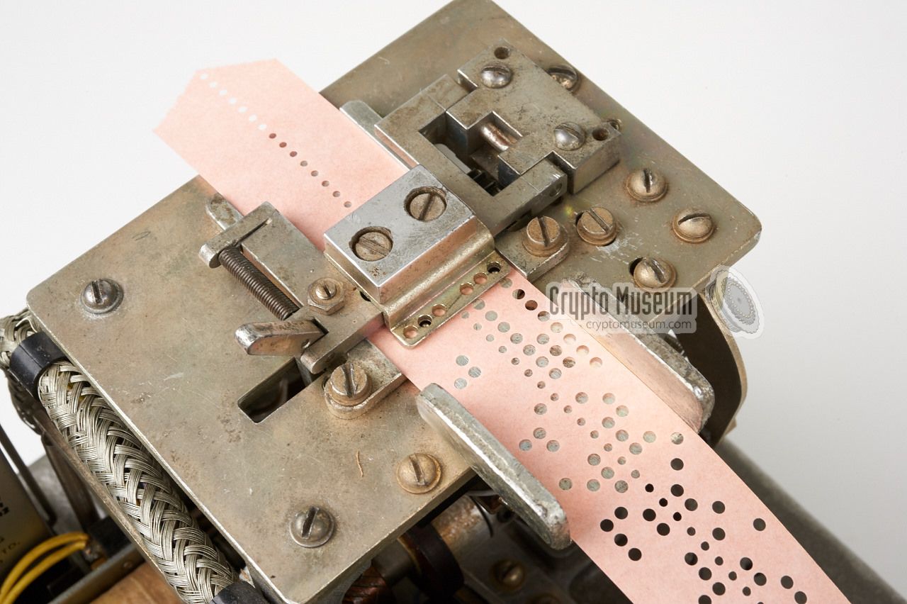
The image above shows an example of a keytape as it is guided through
the tape reader. This means that channel 5 of the tape is at the bottom
(at the edge with the wide margin)
and that the extra channel (6) is added before channel 1 and is now
at the top. Note that the random data on the key tape consists
only of the letters A-Z. This was done
to ensure, in combination with the so-called discriminator,
that only the letters A-Z would appear in the encrypted output, e.g.:
The ciphertext was printed by the built-in printer onto a pre-gummed
paper strip. Once the message was complete, the long paper strip was cut
into pieces of equal length and glued onto a blank message form, so that
it could be sent by morse code or retyped on a teleprinter, e.g.:
Separate tapes were used for encoding and for decoding.
They were idendified by their colour and by the colour of their core.
In the UK, the encoding tape
was generally green and was wound on a blue marked core. The decoding tape
was red and was wound on an orange marked core. In Canada the tapes
were coloured yellow and red respectively. The core for decoding was slightly
wider than the one that was used for encoding.
A sensing switch in the
keytape supply reel (connected to the 3-pin socket at the rear),
informs Noreen of which tape is used. Using a decode tape in encoding mode
does not work.
This was done to avoid double use of a keystream tape.
|
Noreen (BID/590) was developed in the late 1950s and early 1960s,
probably as a lightweight replacement for the rather bulky and heavy
valve-based Rockex one-time tape cipher machine
that had entered service in 1943.
It was developed by the Special Communications Unit
of the Secret Intelligence Service (SIS, now MI6)
at Borehamwood 1 (UK),
where also the secret key tapes
were produced [2].
In the UK, operators were given a two week course at the Foreign Office
at King Charles Street in London, where they were trained in its operation
and maintenance.
Another training school was at Fort Monkton in Portsmouth Harbour [3].
In the late 1960s or early 1970s, the production of Noreen was moved to
HMGCC at Hanslope Park (UK).
Being a one-time tape
device, or mixer, Noreen was used exclusively
for messages at the highest level of secrecy. Whilst intended for
confidential diplomatic traffic of the UK only, the technology was shared
with Canada, with whom the UK historically had a special relationship.
Furthermore, machines were installed in Austrialia and New Zealand,
but only for confidential traffic with the UK. In Australia, they were
installed in Darwin, Canberra and Wellington. Whilst Canada produced its
own key-tapes, the tapes for the UK, Australia and New Zealand
were all prepared in the UK.
During its lifetime, operators and service personnel were not allowed
to take the circuit diagrams or any other documentation out
of the building. They were classified as secret and confidential.
The only piece of documentation that came with each Noreen,
was the destruction protocol that had to be
followed in case of an emergency or compromise.
Any surviving documentation about Noreen (which is now unclassified)
would be greatly appreciated.
|
|
-
Noreen was developed at HMGCC,
Her Majesty's Government Communications Centre,
at Boreham Wood (UK), before the technical development centre was
moved to Hanslope Park (UK) in 1970.
➤ More
|
The drawings below illustrate the operating principle of the Noreen.
Central to the system is a set of five XOR circuits that 'mix' the input
from the keyboard with the keystream tape. Each time a character is typed on
the keyboard, a random character is read from the keystream tape. Both
characters are then 'mixed' by the XOR circuit and are then
printed on
a pre-gummed paper strip.
This operation is generally known as the Vernam Cipher
and such machines are called 'mixers'.
The data from the keyboard
and the keystream tape, each consists of 5 data-bits.
Whenever the 6th hole in the key tape is present however, the data from the
tape reader is printed directly,
thereby effectively bypassing the XOR circuit.
This was used for automatically adding spaces and formatting characters.
Conversion of the 32 keys into 5-bit digital codes is done by means of a
mechanical encoder,
whilst the 5-bit data for the printer is converted into
32 electrical lines by means of a diode matrix. 3
The 32 lines are connected
to a commutator at the back of the printer.
The keytape only contains the (random) letters A-Z, plus formatting data.
In order to ensure that the (printed) output also consists of only letters (A-Z)
and formatting data (SPACE, LF, CR), a discriminator is added to
check the output of the XOR for unwanted characters (the so-called stunt 1
characters).
If, during encoding, a stunt character is encountered,
the input is halted and the key character is output instead.
Next, the key tape is advanced and the next key character is tried, and so on,
until the desired output (A-Z) is yielded 2 . This is then sent to the printer.
At the receiving end, the bypassed character is mixed with the same character
from the key tape, which produces a NULL code. As a NULL code has no effect
in the 5-bit ITA2 code,
it will be ignored and has no effect on the
decoded text or the security of the cipher.
Although some overhead is generated,
it has the advantage that
all ITA2 characters
may occur in the original plaintext, regardless of the
A-Z limitation of the ciphertext. The result could be something like:
When deciphering as described above, the formatting data from the key
tape has to be ignored and any characters entered on the keyboard other than
the letters A-Z, will also have to be suppressed. For this reason, a mode
selector (EN/DE) is available to the right of the keyboard. In deciphering
mode (DE), the machine works as shown in the block diagram above.
➤ More about the Vernam Cipher
|
|
-
In telegraph speak, 'stunt characters' is a common expression for the
control codes: LF, CR, LTRS, FIGS and SPACE.
-
In May 2015, the exact operation of the Rockex/Noreen key tape has
been the subject of a discussion on the Crypto Collectors News Group,
in which the method described here was proposed by Frode Weierud [7].
This has since been confirmed by released NSA documents on Rockex [8]
and by trying it out.
-
As it is not possible to use a diode matrix for a 5-to-32 conversion,
the actual circuit works the other way around: as a 32-to-5 encoder.
Please refer to the description of the printer for further
information.
|
|
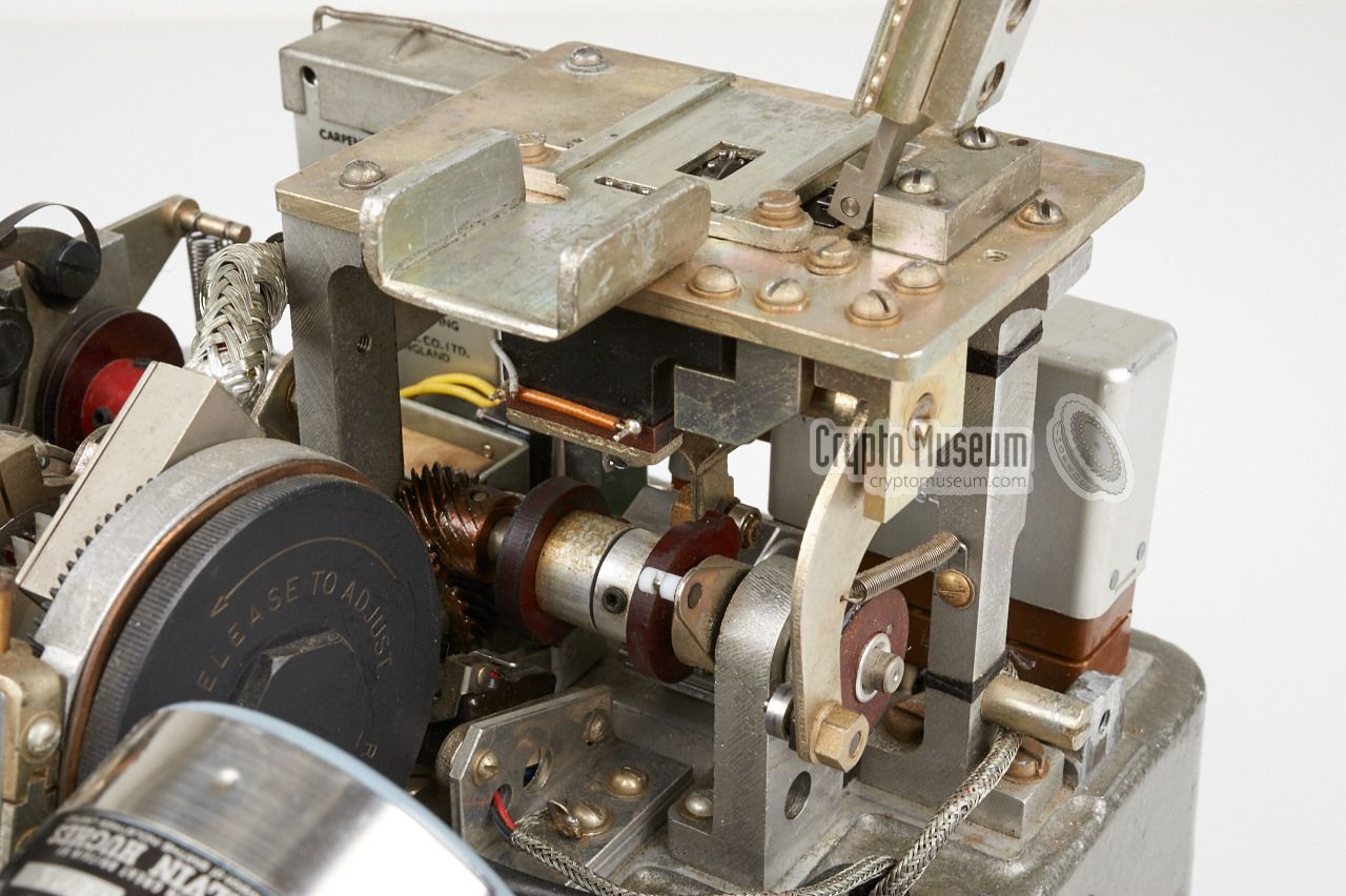
Noreen is built on a die-cast aluminium chassis on which various sub-assemblies
are mounted. At the front is a mechanical teleprinter keyboard, which is nearly
identical to the keyboard of the American Teletype Model 15 teleprinter. At the
top left is a 6-level tape reader
that was probably manufactured by Creed. At the
centre is a paper strip printer with a
two-level rotating print head.
|
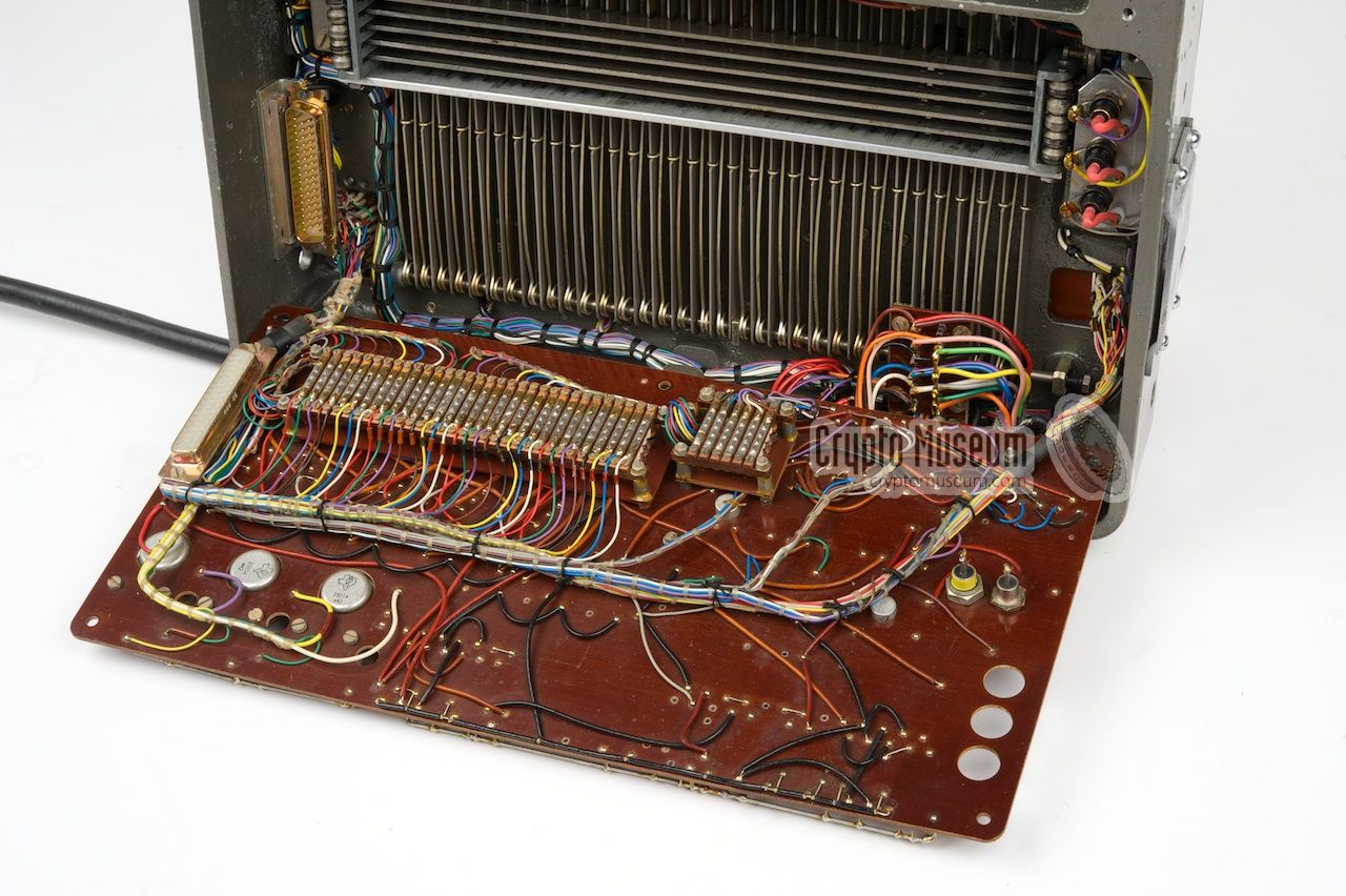
The electronic circuits are hidden in the bottom section of the machine.
They can be accessed by removing the bottom panel, which is held in place
by 4 bolts in the 4 rubber feet. After removing the bottom panel, the electronic
parts are exposed immediately.
They are mounted on a brown Pertinax panel that is held in place
by 5 screws (actually 2 screws, 2 mounting posts and 1 stub).
|
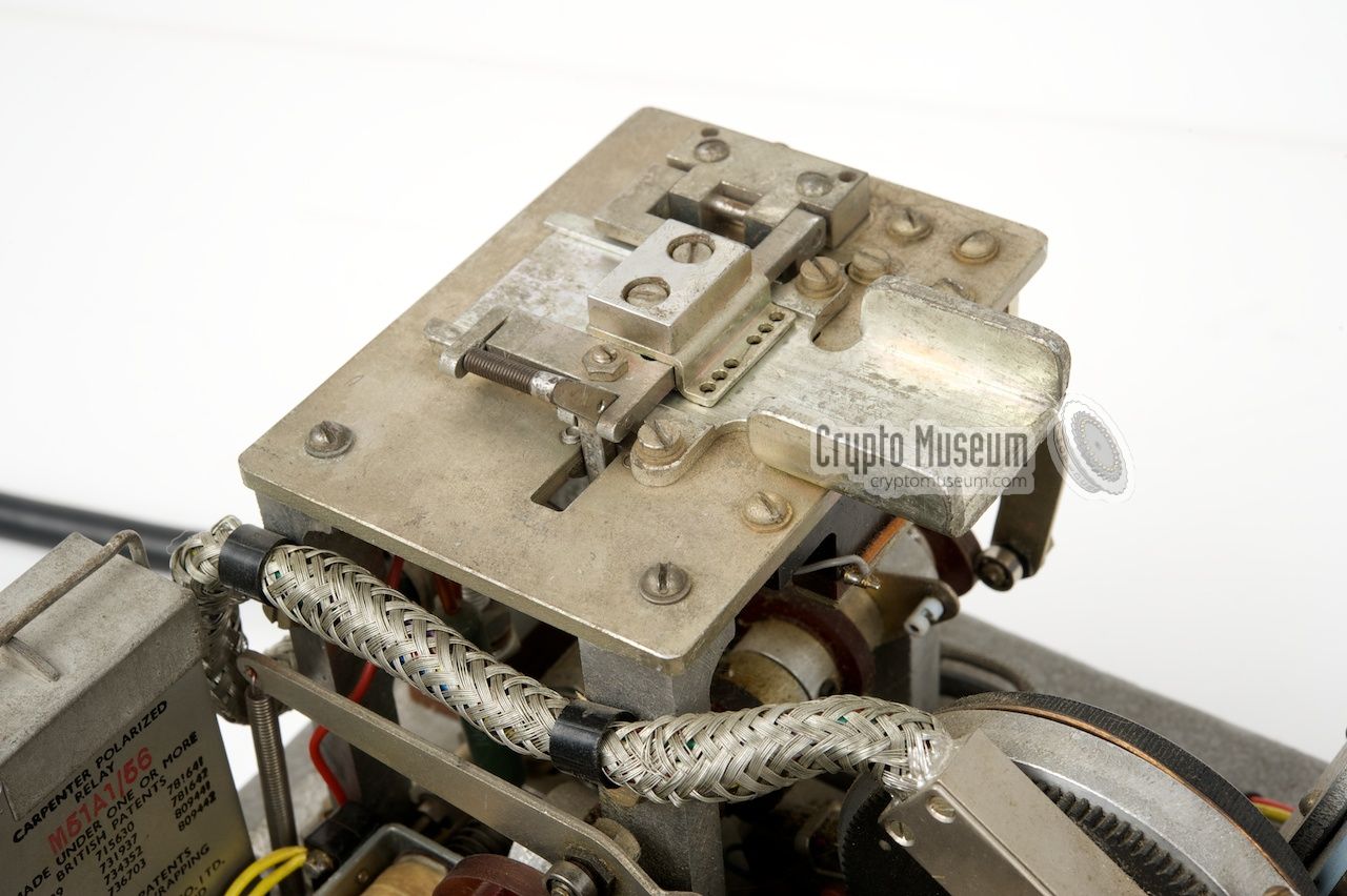
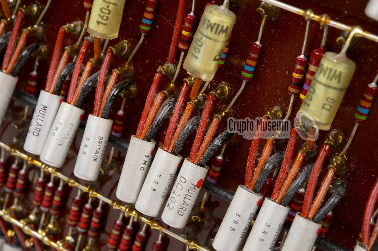
The electronics section contains the
five XOR circuits that are used for
mixing a plaintext character with a keystream character. Each XOR is
built from discrete components, such as the early OC202 and OC204
silicon PNP transistors.
Other circuits are present for controlling the various solenoids and
telephone relays
that are part of the mechanical section at the top of the machine.
These circuits can be recognised by their large power transistor
mounted on a metal carrier
at the reverse side of the circuit board.
One power transistor is mounted to the frame.
|
|
|
|
The keyboard consists of a total of 32 keys; 31 green spring-loaded letter keys,
similar to the ones of the military Teleprinter Model 15, plus a spacebar.
Each key is mounted on a metal arm that engages a
mechanical 32-to-5 encoding matrix
that is located at the machine's bottom side.
The encoder identical to that of the Teletype Model 15 and was probably
bought as an OEM part.
|
When pressing a key, its metal arm is moved down and engages 5 metal bars
that run from left to right. The 5 metal bars represent the 5 data-bits and
each have specific cut-outs that represent the
ITA2 telegraphic alphabet.
The cut-outs can cause a bar to slide sideways, or to stay in place.
The sideways movement of the bars is carried onto a
set of 5 'fingers' that
protrude the surface of the machine and finally engage a set of 5 switches
that are mounted at the right. Together, these 5 lines form the 5-bit code
of the character typed on the keyboard.
|
|
|
When typing, the operator has to wait until the key has been 'processed'.
This processing has an arbitrary length and can take up to several seconds
as the machine automatically inserts spaces, message indicators and
non-printable characters, such as Carriage Return (CR) and Linefeed (LF).
|
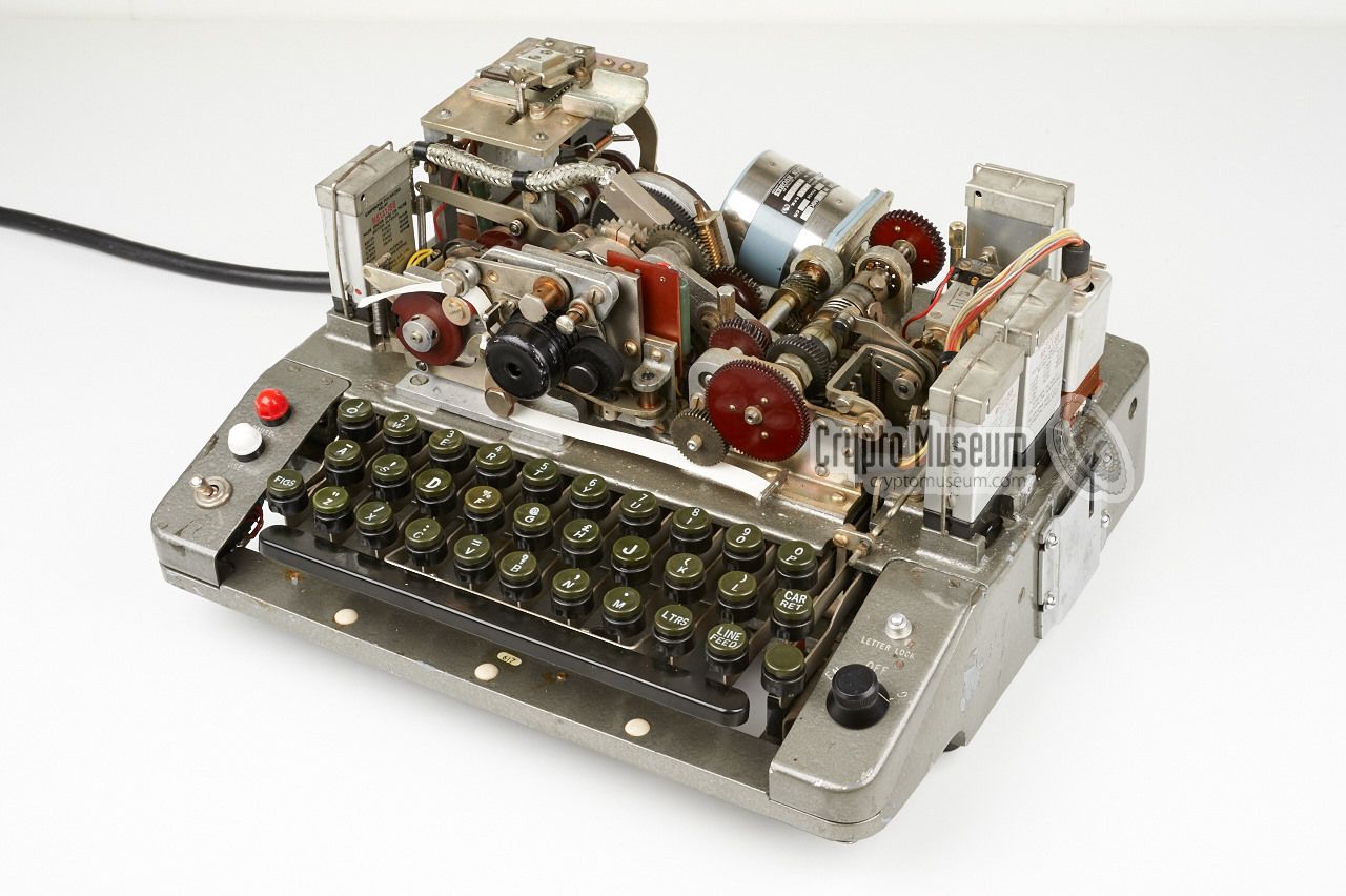
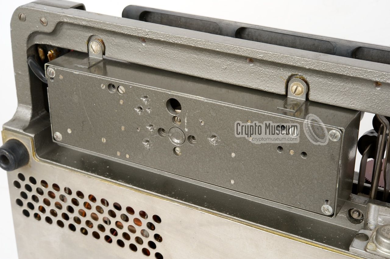
On later version of the Noreen, such as the BID/590/2, an
electromechanical character counter was added in order to find
the approximate end of a line.
The letter counter is housed inside a rectangular metal enclosure that is
mounted underneath the keyboard. It has a small window at the top through
which a bright signal lamp is
visible between/below the keys.
When typing, it counts the letters that have been entered since the
last CR. When it reaches 59 or 60, the lamp is turned on to indicate
that you are approaching the end of line (69 characters).
|
|
|
The character counter was added to prompt the user to insert CR and LF
characters at the end of a line, so that the resulting plaintext,
after decoding on a Rockex, was nicely formatted.
The counter is reset automatically by a
microswitch
mounted under the Carriage Return (CR) key.
|
If the lamp comes on, the user has about 10 characters left before the
end of the current line is reached. It can best be compared to the bell
on an old mechanical typewriter did the same.
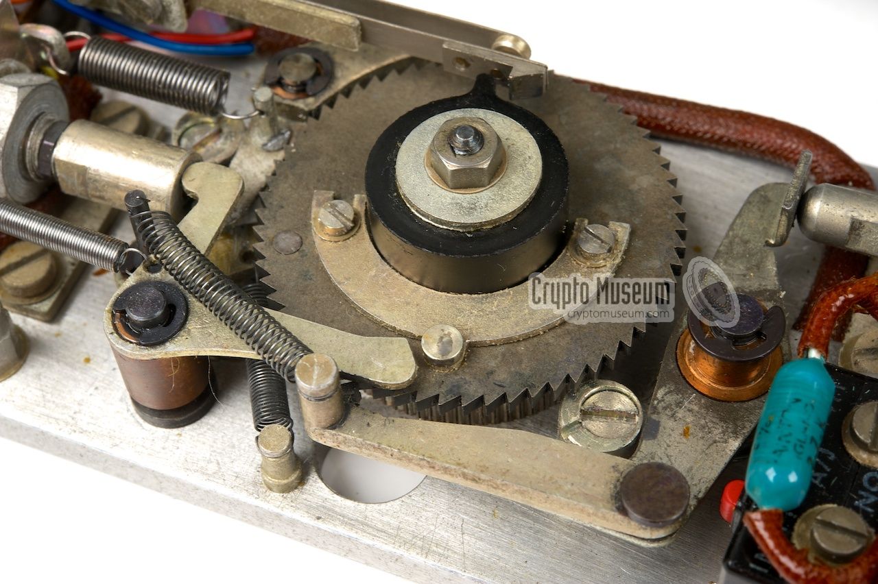
The image on the right shows the interior of the counter.
At the center is a spring-loaded cogwheel
that is advanced by a solenoid at the right,
each time a character is entered on the keyboard.
When the end is reached, a switch will turn on the lamp.
When the user presses CR, a microswitch (mounted under the key)
will cause the leftmost solenoid to release the cogwheel.
|
|
|
The character counter was probably added at a later date, most likely
as a specific feature of the BID/590/2 model. It is not present on early
versions of the machine [1].
Furthermore, the counter contains a 1N4004 diode which was
not yet available in the early 1960s. According to the date stamps on the
telephone relays, the Noreen BID/590/2 shown here, was made in or after 1969.
|
|
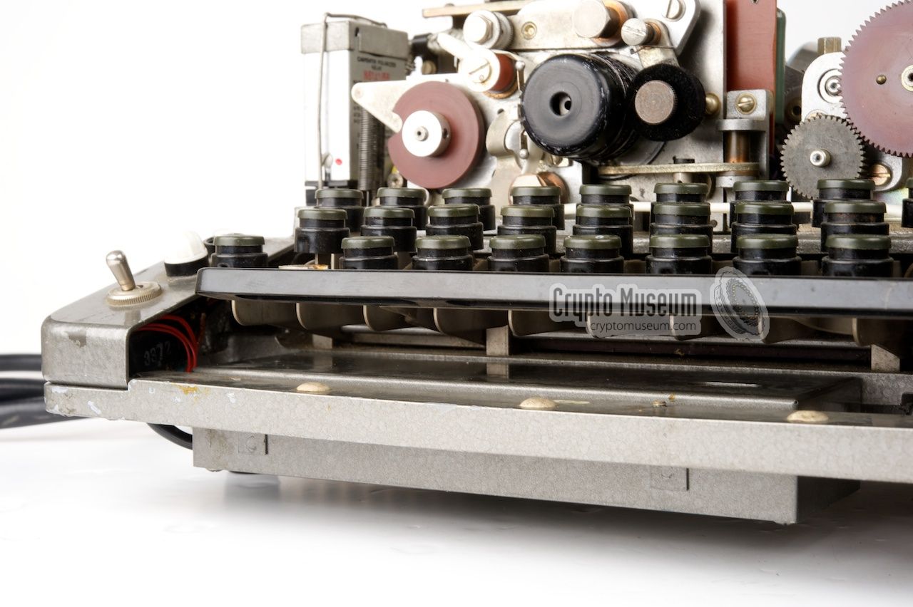
Noreen prints its output directly on a paper strip, just above the keyboard,
that moves from right to left. The paper was supplied on small reels and was
approx. 9.4 mm wide, similar to the paper reels used on the
American M-209
and the Russian Fialka cipher machines.
The reel was placed horizontally in the black paper
holder at the right, and led past the black printing head at the left.
|
Leaving the paper holder at the right, the paper is guided through a
metal guide and then
past the print head
as shown in the image on the right, through the capstan at the top left.
The capstan pulls the paper past the print head.
Where the paper passes the left side of the print head, a small
hammer is released at the right moment, pushing the paper against the letter
wheel. An ink roller at the right ensures that the character is inked before
it hits the paper. The print head has two rows: one with letters (front)
and one with numbers and punctuation marks.
|
|
|
The timing of the printer is guaranteed by a
commutator at the rear end. The 32 electric
lines from the 5-to-32 diode matrix
are each connected to a contact pad of the commutator.
As soon as a voltage-carrying contact is met,
the print hammer is released.
The timing, and hence the letter position, can be fine-tuned
with an adjustment screw that is located
aside the commutator.
|
The print head is located at the front of the machine, just behind the
keyboard. It has two rows with 32 characters each, and is driven by a motor axle
from the rear. The front row of characters contains the letters.
The rear row contains the figures and is only used in FIGS-shift mode.
The diagram below shows the print head as seen from the top of the machine,
in its default position.
At the right is a spring-loaded ink roller that is pressed against the character
ring to ensure that it is constantly inked. A blank paper strip is fed from the
right, guided below the print head, and then
upwards along the left side of the print head,
where a hammer is released exactly at the right moment,
pushing the paper against the inked character ring.
When FIGS-shift is active, a solenoid temporarily moves the print head towards
the front of the machine, as shown here:
The table below shows the layout of the print head going clockwise when
looking at the print head from the front of the machine. The order of
the characters corresponds to the ITA2 table,
when all bits are placed in reversed order
(i.e. channel 1 → bit 4 and channel 5 → bit 0).
The yellow line is the character row that is closest to the front of the machine.
The red line represents the shifted characters (FIGS) that are on the rear
character ring, as shown in the image above.
|
| 01 | 02 | 03 | 04 | 05 | 06 | 07 | 08 | 09 | 10 | 11 | 12 | 13 | 14 | 15 | 16 | 17 | 18 | 19 | 20 | 21 | 22 | 23 | 24 | 25 | 26 | 27 | 28 | 29 | 30 | 31 | 32 |
| Nul | 5 | CR | 9 | SP | £ | , | . | LF | ) | 4 | @ | 8 | 0 | : | = | 3 | + | Enc | ? | ' | 6 | % | / | - | 2 | Bel | Fig | 7 | 1 | ( | Ltr |
| Nul | T | CR | O | SP | H | N | M | LF | L | R | G | I | P | C | V | E | Z | D | B | S | Y | F | X | A | W | J | Fig | U | Q | K | Ltr |
|
The blue cells are blanks that take the place of the stunt characters.
They are actually cut-out from the character ring, so that they appear as a
space in the printed output. This way, the end-of-line characters
carriage return (CR) and line feed (LF), both of which are
used to format the printed output on Rockex, will appear as a SPACE in the
output of Noreen's paper strip printer.
➤ ITA2 character table
|
The timing of the printer is controlled by a so-called
commutator that
is mounted at its rear side. It is driven by the same axle as the print head
so that its movement is synchronous to the print head. The commutator can
be seen as a rotary switch with 32 contacts, one for each character.
The actual operation of the commutator is slightly more complex than
what is suggested in the block diagram at the top of this page.
As it is not possible to use a diode matrix for a 5-to-32 decoder, it is
used in reverse: a 32-to-5 encoder, the output of which (B) is compared to
the 5-bit output of the cipher unit (A). As soon as the two are identical
(A=B), the hammer is released.
The simplified block digram above shows how the commutator works.
The comparator (that senses the A=B condition) consists of
5 individual XOR circuits, the outputs of which are merged in a wired
OR. The output of the OR is inverted and then used to drive the hammer
solenoid.
|
|
Noreen has a non-standard 6-level Creed tape reader, which is mounted at
the left rear, in such a way that the tape enters the reader from the
right and leaves it at the machine's left side. The drawing below shows
the reader when seen from the top right with the tape running upwards.
|
The reader accepts a tape width of 7/8" or 22.2 mm, which was also used
on other 6-level tape readers at the time. The reader has 6 channels:
three at either side of the sprocket hole. In order to prevent the tape
from being loaded the wrong way around, there is an extra margin at the left.
The image on the right shows Noreen's key tape reader, as seen from the right,
with a suitable keystream tape loaded. When enciphering, the tape moves away
from the viewer (i.e. towards the left of the machine). In this view, the
extra data channel (i.e. the 6th hole) is at the right.
|
|
|
The remaining five channels represent the normal 5 bits of a 5-level
punched tape, in ITA2 format. As seen here, the channels are in the
order 543216, which means that channel 1 is adjacent to channel 6.
As it might be very difficult to find any surviving 7/8" paper tape,
the drawing below can be used as a guide when cutting standard 1"
(8-level) paper tape to size.
|
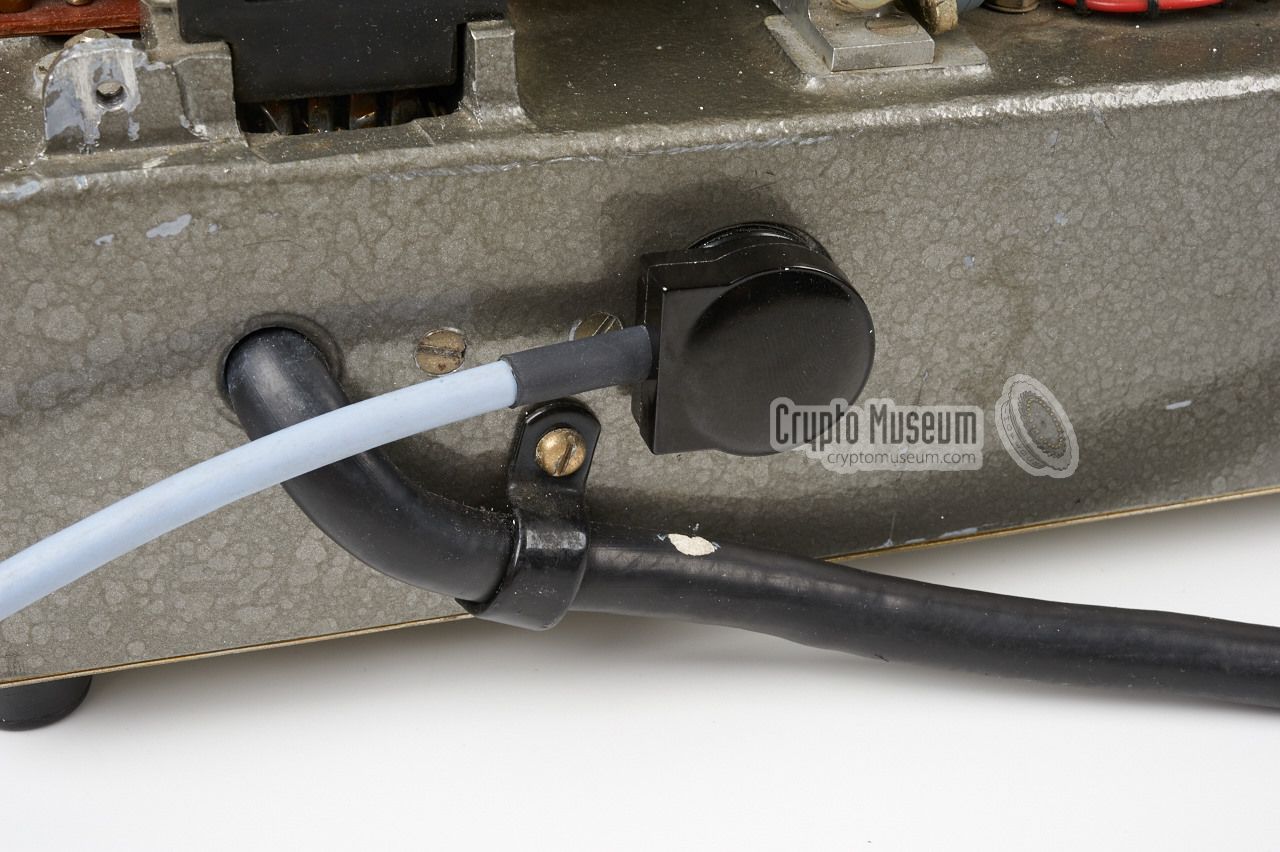
Noreen was powered by an external 12V/24V DC source that was connected to the
fixed 1.5 metre cable that runs from the back of the machine.
At the end of this cable is a military
CANNON MS3106E-18-1S connector.
Although it is known that in some cases Noreen was powered by a mains
power supply unit, this was not officially allowed.
In order to avoid TEMPEST problems, it was decided that the machine
had to be powered by a shielded 12V/24V battery at all times.
The battery came in a wooden box with a removable top lid,
that had a shielding wire cage on the inside in order to avoid unwanted
emanations. At the side of the wooden box was a
CANNON MS3102E-18-1P connector
that mates with Noreen's power cable. Inside the box were two power
sources: a heavy duty 12V/24Ah lead-acid battery and a light duty 12V/7.5Ah
battery that consists of two 6V batteries connected in series.
The battery connector is layed out as follows:
The image above shows the pin order of the battery box [3]
when looking onto the pins of the male receptacle. The pins are marked A-H
starting at the top right and running clockwise. The two pins at the centre
are marked I and J. Thanks to David White for specifying the wiring [3].
|
| Pin | Voltage | Description | Colour |
|
|
| A | GND | Ground | Frame |
| B | +0V | Not connected (spare) | - |
| C | - | Clutch coil, not connected (spare) | - |
| D | +0V | Heavy duty battery (+) | Orange |
| E | -12V | Heavy duty battery (-) | Black |
| F | +0V | Heavy duty battery (+) | Yellow |
| G | -12V | Heavy duty battery (-) | Blue |
| H | +0V | Heavy duty battery (+) | Green |
| I | -24V | Light duty battery (-) | Brown |
| J | -12V | Light duty battery (+) | Mauve |
|
Note that with Noreen all voltages are referenced from the (+) terminal
of the large battery. This means that this line is called +0V, whilst
the operational voltages are at -12V and and -24V.
The main 12V source (i.e. the heavy-duty battery) is used for the
moving parts, such as the driving motor, the tape reader, the printer
and the solenoids, whilst the light-duty battery provides the extra
voltage needed for the electronic circuits that are mounted
at the bottom side of the unit.
As original batteries are no longer present and suitable alternative
batteries will be large and cumbersome, it might be best to build a
small modern PSU for demonstration purposes. As part of the
restoration
of the machine shown here, we've built a suitable small electronic PSU
that measures no more than 20 x 20 x 10 cm. It has a
10-pin CANNON socket at the front,
so that Noreen can be connected directly.
At the rear it has a 3-pin socket
for connection to the mains.
|
The keystream tape supply reel, is normally attached to the right side of
the machine, in such a way that the random paper tape can be fed directly to
the tape reader at the top left. In order to allow the machine to discriminate
between cipher and decipher tape, each type had a different
width of the tape core.
The supply reel mechanism containes a switch that senses which type of tape core
is present. This switch is connected to the 3-pin Bulgin male socket at the rear:
|
July 2015
When we acquired Noreen in January 2015, the machine was in pretty
bad condition.
It was clear that the machine had seen some action (as indicated by the
usage counter under the tape reader)
and it had accumulated quite a bit of dust and dirt
in the 30+ years that it had been in uncovered storage since it was
decomissioned in the early 1980s. In other words: it badly needed attention.
|
As this was the first historical British cipher machine
in our collection, we were determined to get it going again.
Ideally, we would like to be able to use it for demonstrations.
After cleaning the mechanics and applying a fresh drop of oil here
and there, we made a list of missing items.
The largest missing part is the top case shell which normally covers the
machine's mechanical parts. Although we will probably never find this part,
we do not consider it a problem. Noreen can be used perfectly well without
it, and it gives us the opportunity to see its
beautiful inner life.
|
|
|
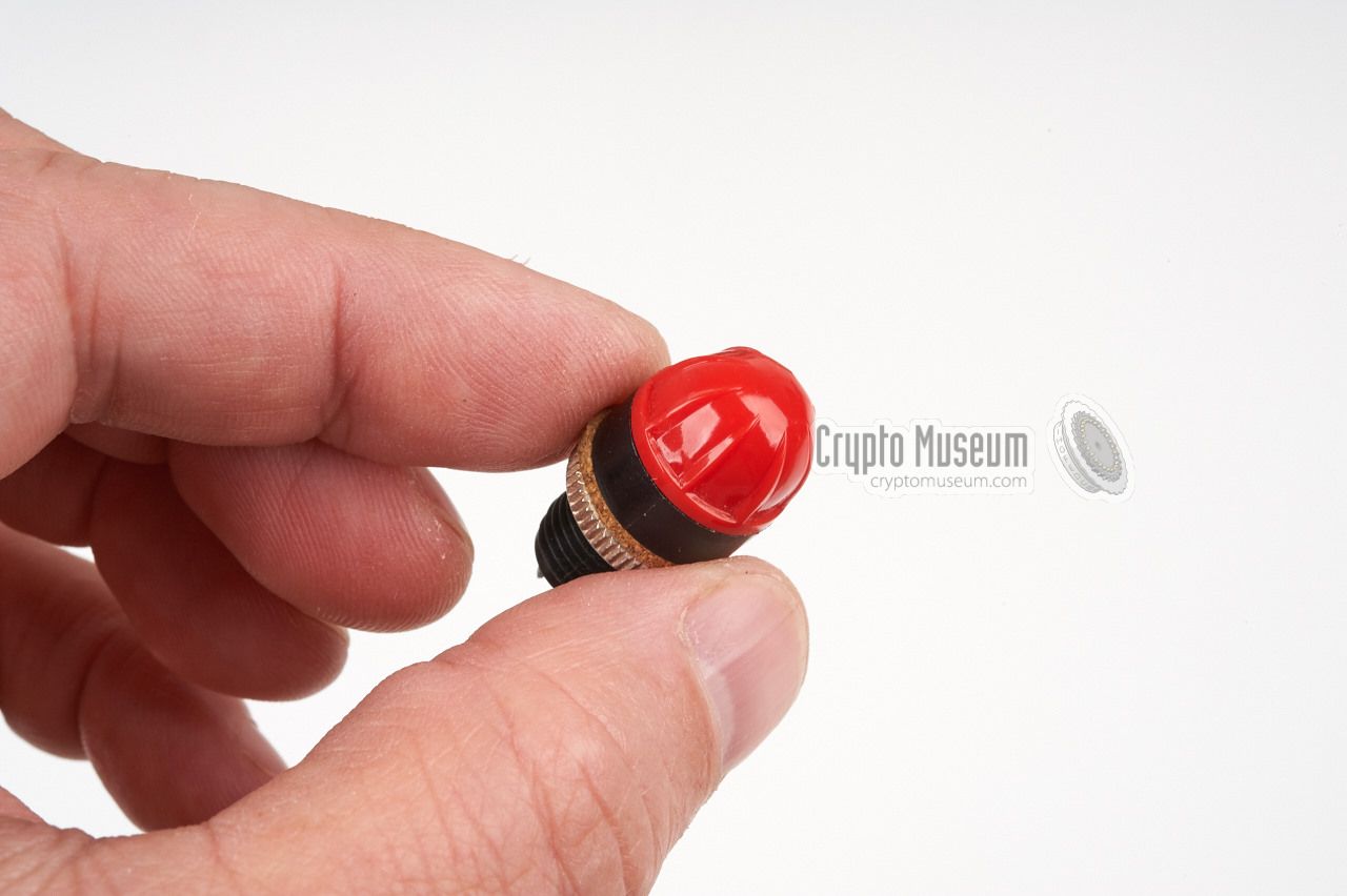
As you can see in the image above, one of the key tops (the letter 'Z')
was missing, just like the red lens of the upper indicator light to the
left of the keyboard. Both items would be difficult to find.
The paper feed tray for the strip printer (not shown here)
came without its transparent top lid, but again
this was not considered a problem as the machine can be used without it.
|
Another challenge was the
uncommon key tape reader,
which requires a 6-channel paper tape,
rather than a more common 5-channel or 8-channel one.
Consequently, it needs very rare paper tape with
a width of 7/8". Apart from that, the key tape format
was largely unknown to us.
The latter problem was solved with help from the Crypto Collectors
News Group on Yahoo. After long in-depth discussions we were able
to define the tape format with reasonable certainty. And after a
tip from one of the members, we were able to secure some
suitable tapes on eBay.
|
|
|
In the meantime, we had built a
small power supply unit that
could be connected directly to Noreen, instead of the complex
battery unit that was, of course, missing as well.
When we powered Noreen up after a sleep of 30+ years,
the electronics worked surprisingly well and we were soon able
to type our first clear message.
As the key tape feeder (another missing part) has a built-in
switch that senses whether an encryption or
decryption key
tape is present, we had to make a
dummy cable with a slide switch
that simulates the sensing switch of the feeder.
|
|
|
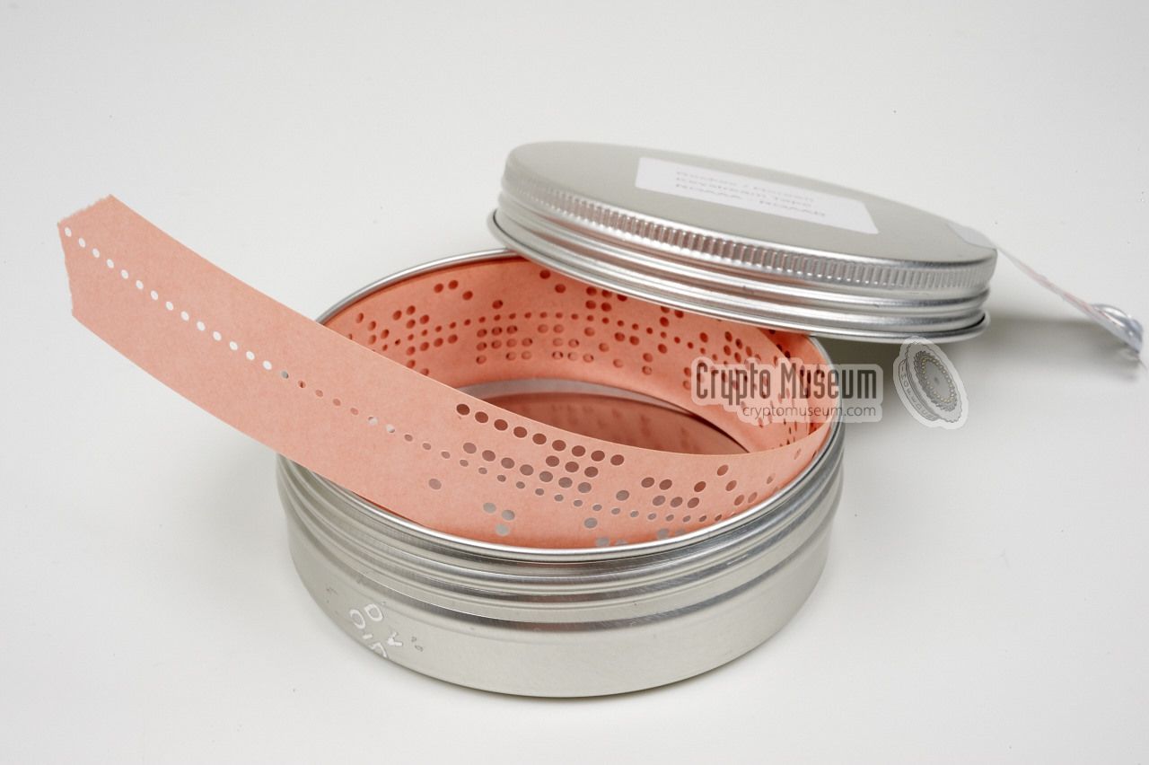
Now the time had come to encode or decode our first real message.
Whilst we were in Friedrichshafen, a package had arrived in the mail.
Inside it was a small can with a short key tape.
It was created by Richard Girling, one of the members of the Crypto Collectors
News Group, and should be used in combination with the ciphertext message
he had sent previously via regular e-mail.
|
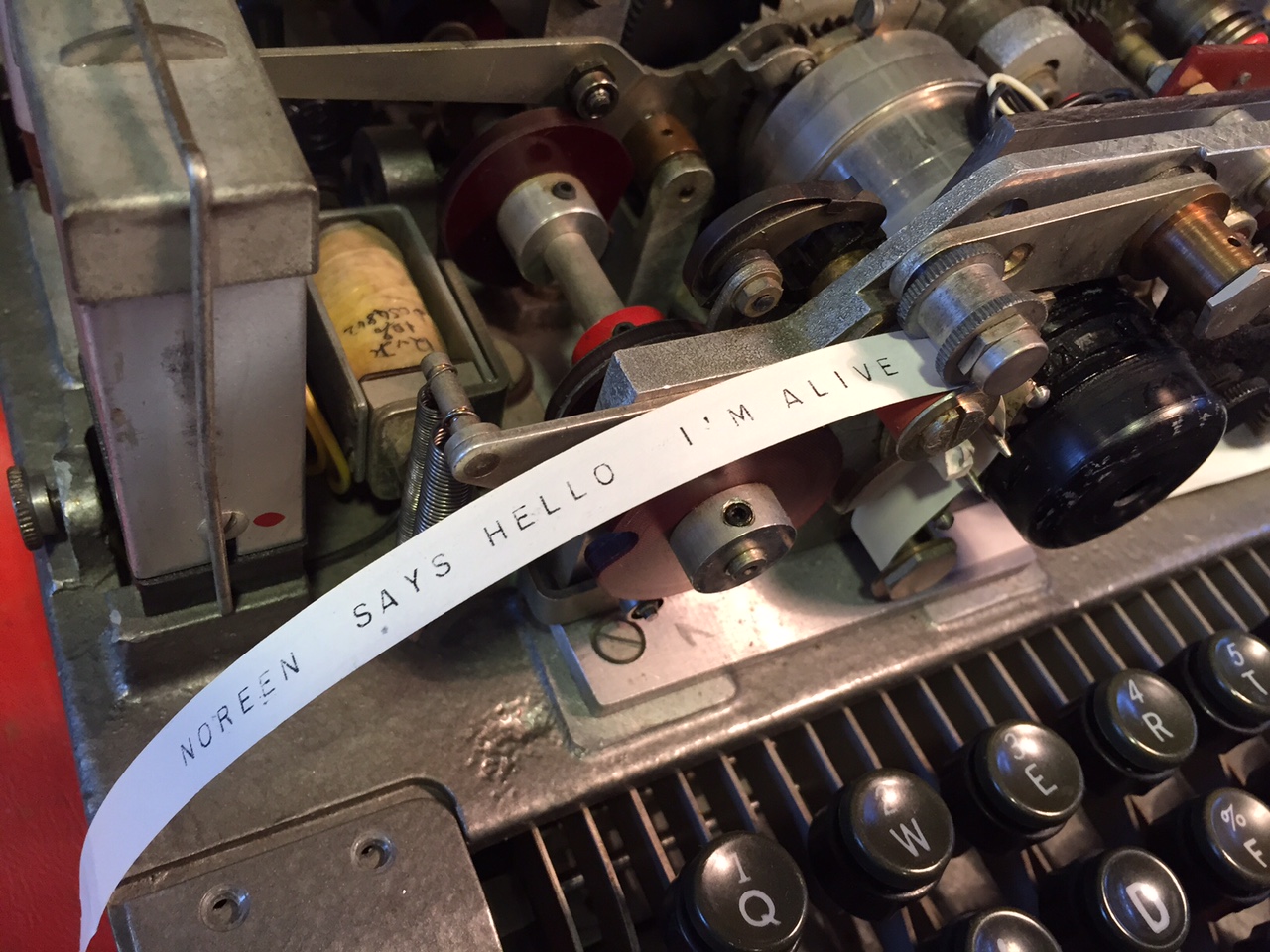
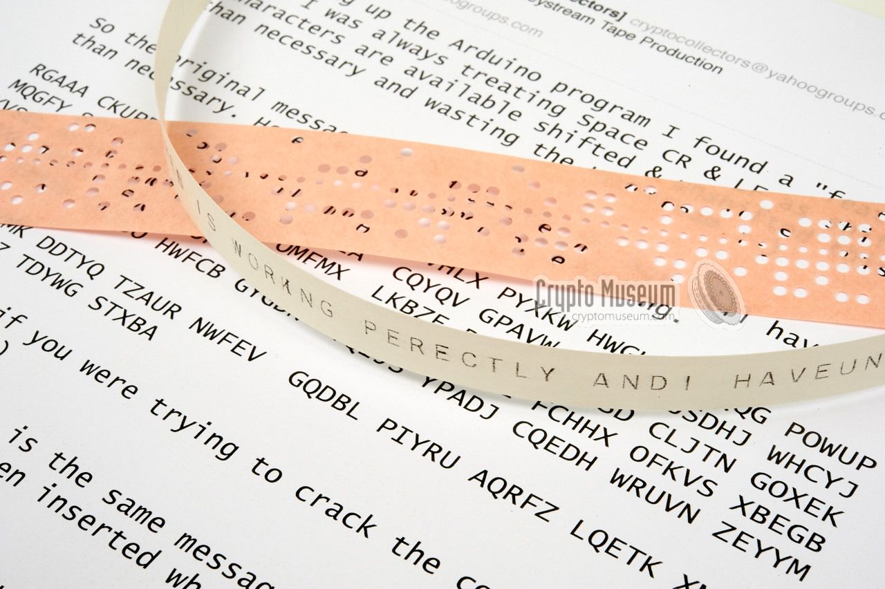
After some further cleaning of contacts and testing with various
in-house created key tapes, we connected the dummy cable and set
all switches to Decode (DE). Then, after making a few
corrections to Richard's key tape, we loaded it into the tape reader
and were able to decrypt our first Noreen message. Perhaps you can
imagine the joy we felt when we saw
readable plaintext appearing
on the narrow paper strip.
As you can see, the printer sometimes 'forgets' to advance the paper,
resulting in a double character, but this issue will be dealt with later.
|
|
|
Next we tried to Encode (EN) a message and this worked flawlessly.
Any character can be used in the plaintext, and the ciphertext is
nicely formatted in groups of 5 letters (A-Z) each, separated by
spaces. Not only does this mean that Noreen is working correctly,
it also proves that the key tape format was deduced correctly.
Many thanks to all who have contributed to this result.
|
-
The exhibition in Hut 1 was closed down
in September 2013. Current whereabouts of the Noreen are unknown.
|
|
Crypto Museum are currently looking for the following Noreen-related items:
|
Key top for the letter 'Z'
Update April 2015: Found in the US.
Red lens for indicator light
Update June 2015: Found in Germany.
- Metal top cover
- Copy holder
6-level paper tape
Update May 2015: Found in the US.
- Key tape feeder
External assembly mounted at the right side of the machine
(with built-in tape sensing switch).
- Transparent cover for printer supply reel
This is the transparent cover that sits on top of the horizontally
placed printer strip supply reel, to the right of the printer.
- Documentation
Any documentation about Noreen BID/590 would be most welcome.
|
|
|
|
Any links shown in red are currently unavailable.
If you like the information on this website, why not make a donation?
© Crypto Museum. Created: Tuesday 13 January 2015. Last changed: Saturday, 30 April 2022 - 09:55 CET.
|
|

|
|
|
| |