|
|
|
|
|

|
|
← Terma Phone
Military tactical terminal
ET-10 is a tactical terminal for
secure voice communication,
developed and built by Terma A/S in Danmark in the late 1990s.
It is in fact a digital cryptographic phone, suitable for connection to
Eurocom-based networks with 16 or 32 Kb/s data rate.
It was introduced with the German Armed Forces in the mid-2000s and phased
out again in 2012.
Also known as NSN 5805-22-269-2579.
|
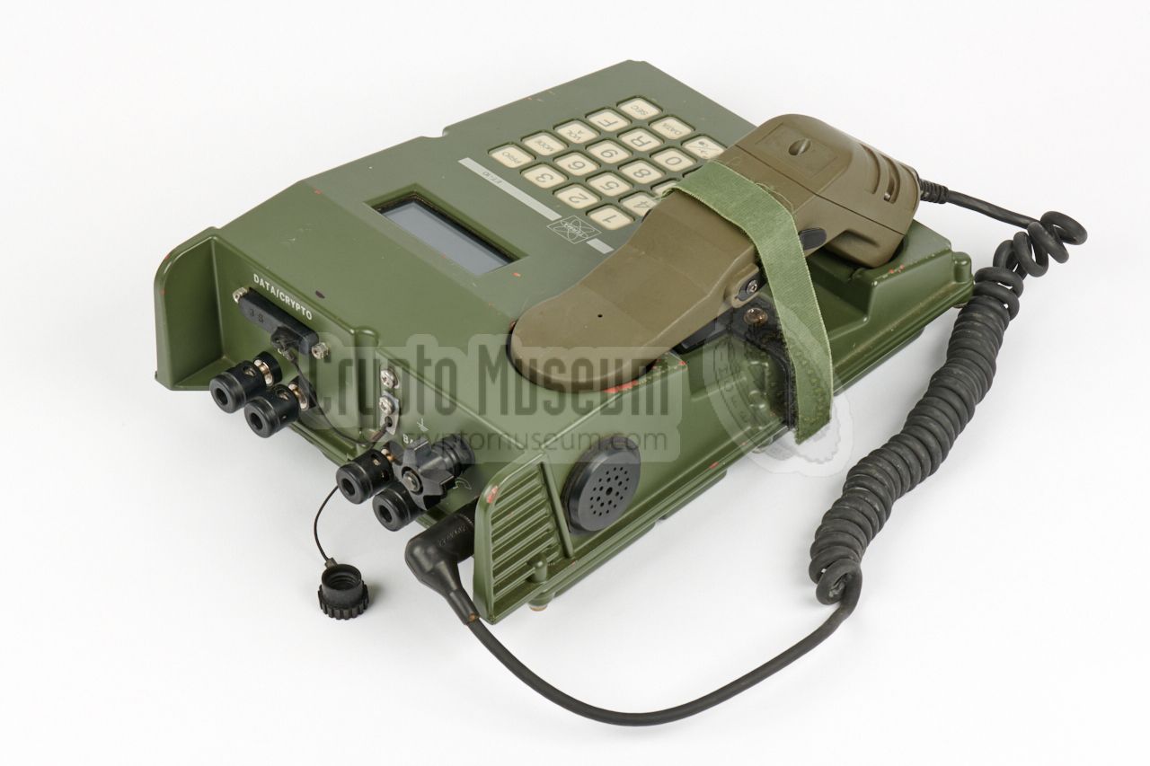
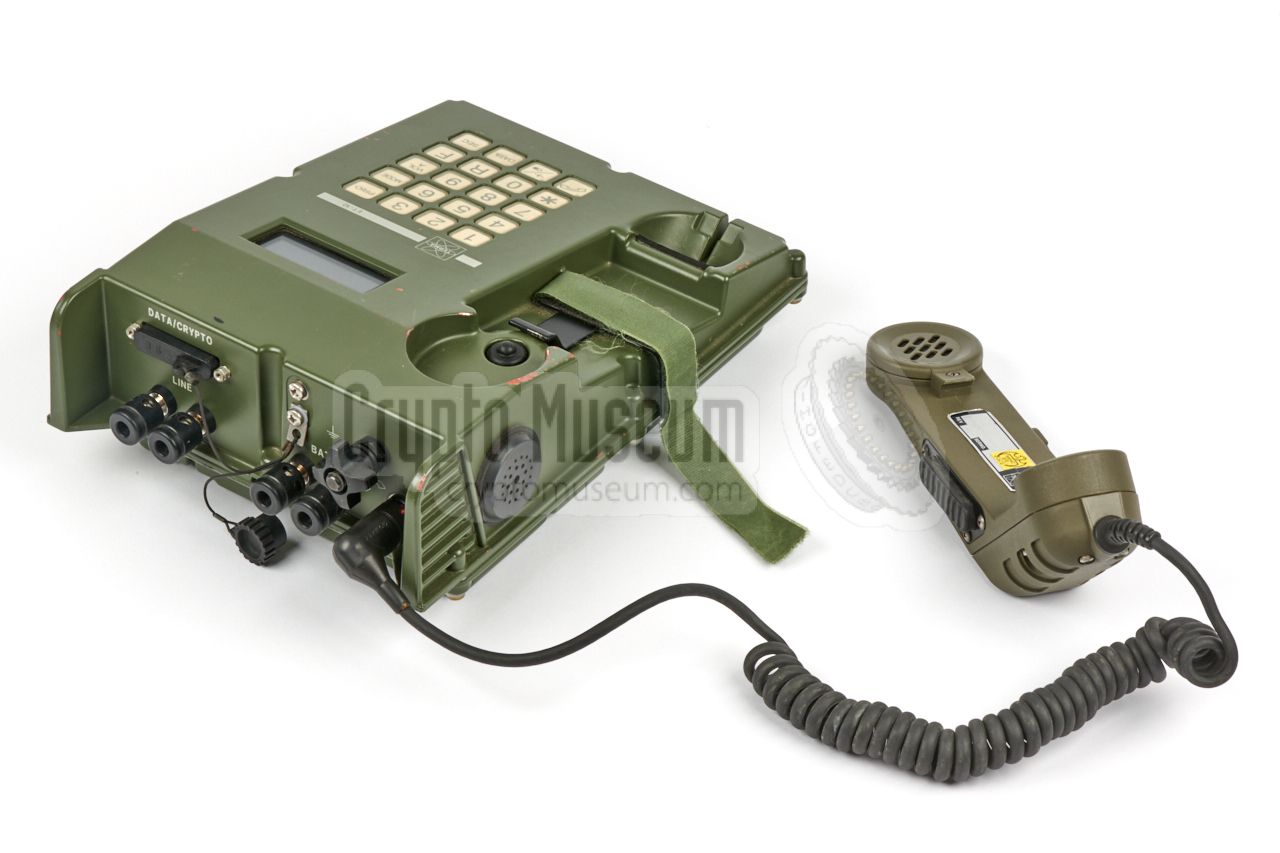
The image on the right shows the basic unit of the ET-10.
Is is housed in a die-cast aluminium case and resembles a normal telehone set.
At the left is the cradle with the handset, which is made of strong green
plastic, connected at the rear.
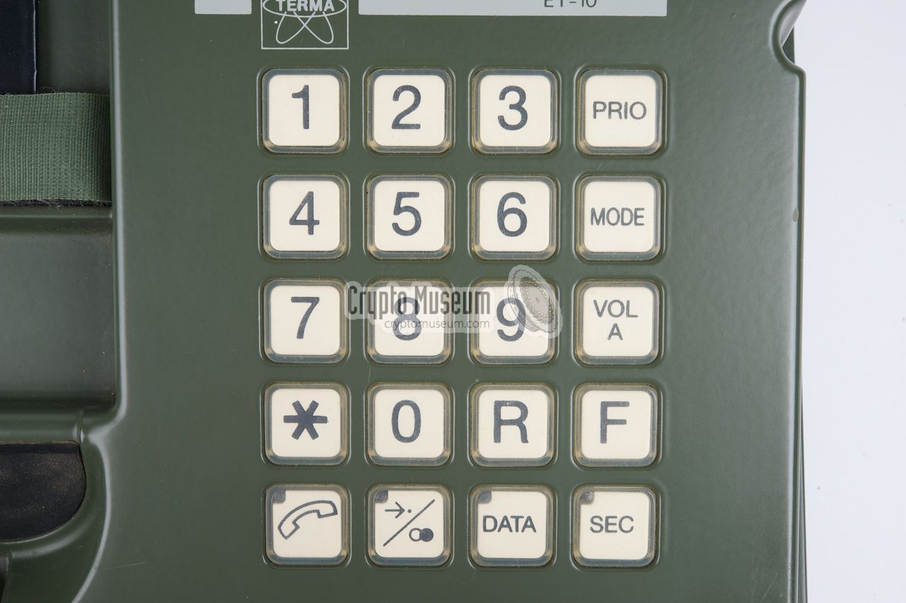
At the right is a keypad with 20 push-buttons.
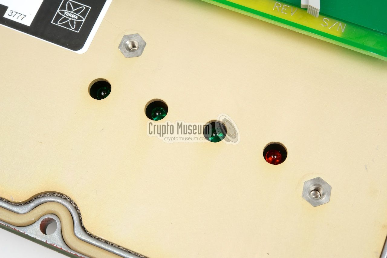
The bottom row of keys have
a built-in LEDs. Above the keypad is a
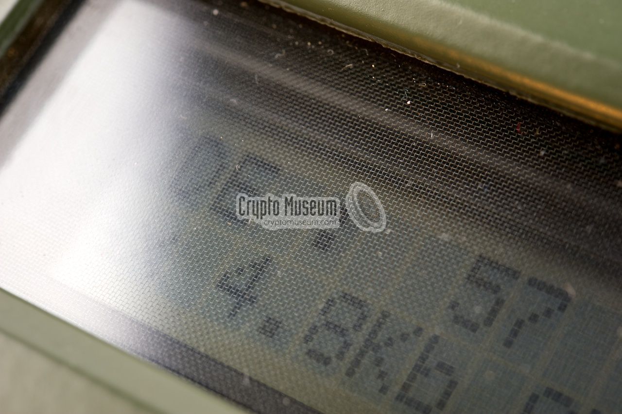
2-row 16-character LCD display.
At the rear
are connections for the handset, the (digital) telephone line
and the power supply (or battery). Furthermore there is a 25-way D-type
connector marked Data/Crypto.
|
|
|
The ET-10 is intended for connection to digital telephone networks based
on the military NATO EUROCOM standard, with a data transfer rate of 16Kb/s or
32Kb/s. It is suitable for voice, data, fax and teleprinter communication
with a variety of transmission speeds.
See the table below for a full list of the available modes.
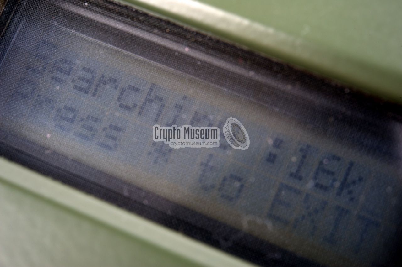
The unit is powered by any polarity
power source between 15 and 28V. When first switched on, it tries to
auto-sense the speed of the network (16 or 32 Kb/s).
|
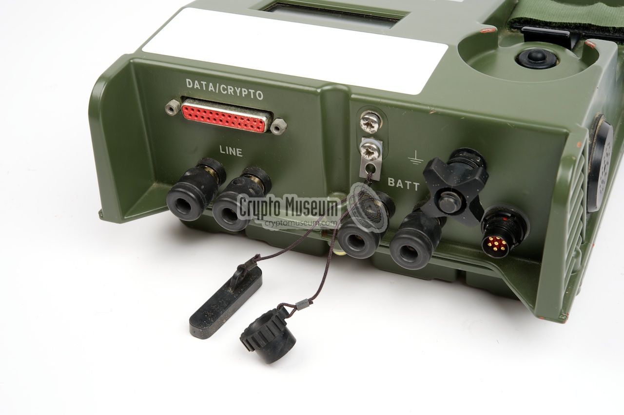
The diagram below shows the ET-10 terminal, seen from the rear, with the handset
off-hook. All user controls are at the sloped top panel, except for the
half-duplex push-to-talk switch (PTT) which is located at the side of
the handset. Above the keypad is the EMC-shielded LCD display.
All connections to the ET-10 are at the rear.
The unit is powered by a 18-32V DC source that is connected to the two black
terminals marked 'BATT' by means of banana-type plugs or blank wires.
Polarity may be reversed. The two other black terminals are for connection
to the line.
|
The unit is suitable for connection to a 2-wire 16-32 Kb/s digital network.
The blank ends of the 2-wire line can be claimed directly onto the terminals.
Banana-type plugs can also be used. Optionally, a ground-wire
can be connected.
At the top left is a 25-pin female D-type socket, marked DATA/CRYPTO.
This connector features a full V.24 serial port, allowing the connection
of external peripheral equipment, such as
a fax, a teleprinter (telex) or a computer (data).
It might also have been used for connection of a key loader (filler),
but this is currently not certain.
|
|
|
At the bottom-right is the 7-pin NF-7 socket to which the handset
should be connected, as shown in the
overview image
at the start of this section.
|
|
The ET-10 can be used in a variety of operation modes, including fax, data
and teleprinter (German: Fernschreiber). The default mode is VOICE.
The required mode is selected by pressing the
MODE button
and typing a 2-digit MODE-number. The following modes are recognised:
|
| MODE | Type | Data rate | Class | Remark |
|
|
| -- | VOICE | 16-32 Kb/s | - | Default mode |
|
|
| 21 | FS | 50 Bd | 2 | Fernschreiber (telex), 50 baud, class 2 |
| 22 | FS | 75 Bd | 2 | Fernschreiber (telex), 75 baud, class 2 |
| 23 | FS | 100 Bd | 2 | Fernschreiber (telex), 100 baud, class 2 |
| 24 | FS | 110 Bd | 2 | Fernschreiber (telex), 110 baud, class 2 |
| 25 | FS | 150 Bd | 2 | Fernschreiber (telex), 150 baud, class 2 |
| 26 | FS | 200 Bd | 2 | Fernschreiber (telex), 200 baud, class 2 |
| 27 | FS | 300 Bd | 2 | Fernschreiber (telex), 300 baud, class 2 |
|
|
| 31 | FS | 200 Bd | 2 | Fernschreiber (telex), 200 baud, class 2 |
| 32 | FS | 300 Bd | 2 | Fernschreiber (telex), 300 baud, class 2 |
| 33 | FS | 600 Bd | 2 | Fernschreiber (telex), 600 baud, class 2 |
| 34 | FS | 1200 Bd | 2 | Fernschreiber (telex), 1200 baud, class 2 |
| 35 | FS | 2400 Bd | 2 | Fernschreiber (telex), 2400 baud, class 2 |
| 36 | FS | 2400 Bd | 3 | Fernschreiber (telex), 2400 baud, class 3 |
|
|
| 42 | Fax | 2.4 Kb | 4 | Fax, 2400 baud, class 4 |
| 43 | Fax | 4.8 Kb | 3 | Fax, 4800 baud, class 3 |
| 44 | Fax | 9.6 Kb | 4 | Fax, 9600 baud, class 4 |
| 45 | Fax | 2.4 Kb | 3 | Fax, 2400 baud, class 3 |
| 46 | Fax | 16 Kb | 1 | Fax, 16 Kb/s, class 1 |
| 47 | Fax | 32 Kb | 1 | Fax, 32 Kb/s, class 1 |
|
|
| 52 | Data | 2.4 Kb | 4 | Data, 2400 baud, class 4 |
| 53 | Data | 4.8 Kb | 4 | Data, 4800 baud, class 4 |
| 54 | Data | 9.6 Kb | 4 | Data, 9600 baud, class 4 |
| 55 | Data | 2.4 Kb | 3 | Data, 2400 baud, class 3 |
| 56 | Data | 16 Kb | 1 | Data, 16 Kb/s, class 1 |
| 57 | Data | 32 Kb | 1 | Data, 32 Kb/s, class 1 |
|
It is currently not know how the cryptographic key was entered into the ET-10.
It is possible that this was done manually, via the keyboard, but it is more
likely that a purpose-built key loading device was used. Such a key loader
(or: filler) was probably connected to the
Data/Crypto connector at the rear.
|
|
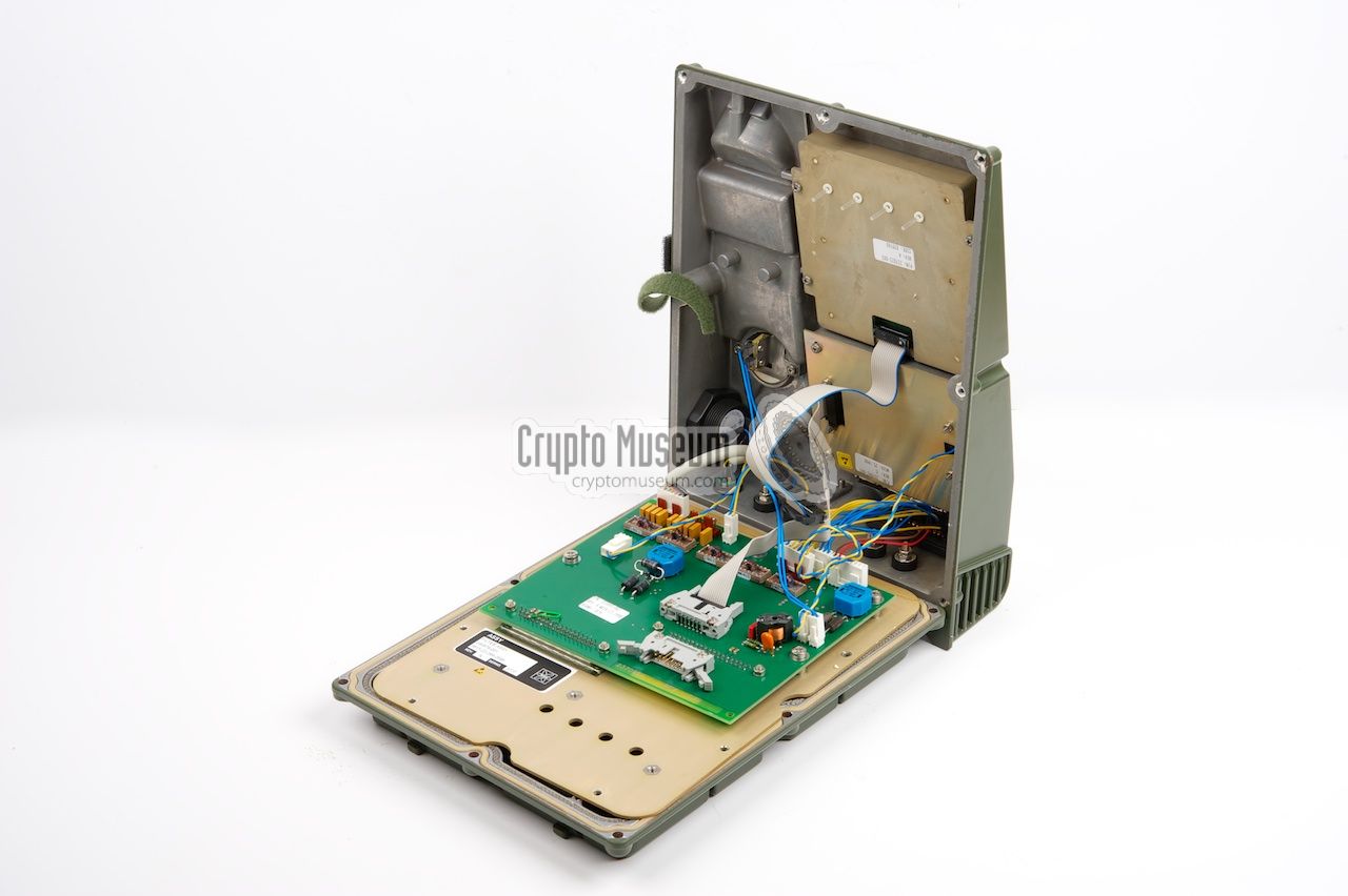
The ET-10 is a very robust terminal with a case that fully complies with
TEMPEST regulations. The unit can be opened by removing 8 cross-head bolts
from the bottom. Raising the top half of the case, presents a
mixed impression
of the quality of the unit: both professional and amateuristic.
|
The top half of the case holds the display and keypad, which are both housed
in a TEMPEST-proof enclosure. The display even has a
fine metal grid at the front,
as to avoid unwanted eminations. This is the professional part.
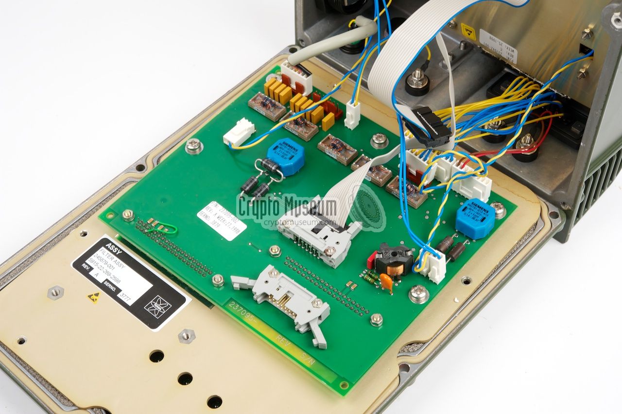
At the bottom half is an interconnection board that gives a somewhat
unorganized impression. Connectors are spread all over the board and
the wires are not aligned nicely. Furthermore, the connectors are not
sealed to their sockets. This PCB, called the Filter Assembly, is definitely
not built to military standards.
|
|
|
The real beauty of the ET-10 however, is hidden underneath a
thick metal plate
at the bottom. Removing this panel, reveals the actual
digital board
of the unit, called the Transmission Circuit.
It is a multi-layer PCB with a large number of (custom-built) integrated
circuits on one side.
|
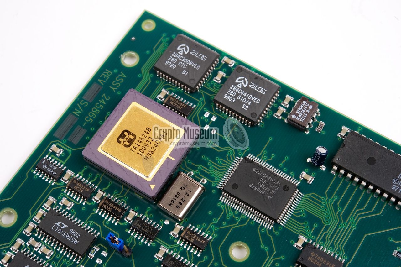
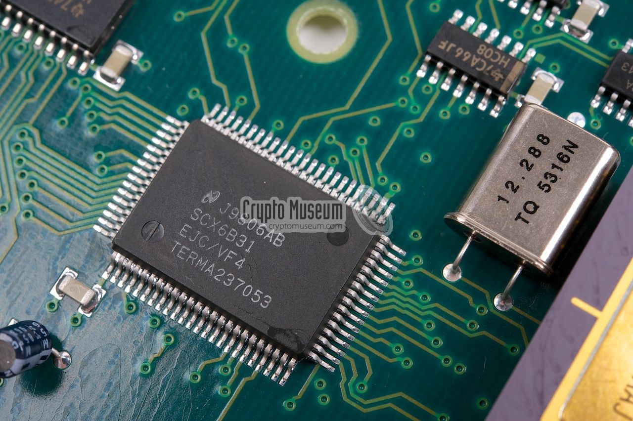
The citcuit is built around a Temic 80C32 micro-controller
[2], running at 44MHz, with external Flash-memory, EEPROM (firmware) and
battery-backed non-volatile SRAM
(8KB) [3].
A series of peripheral chips is present, such as
multi-serial controler (Z84C4410),
a Counter/Timer Circuit (Z84C3008)
and some RS-232 transceivers.
Voice data is digitized with a CML FX609
Continuous Variable Slope Delta Modulator [6] (CVSD).
Various custom designed chips (ASICs and CPLS) are used
as 'glue-logic', whilst a
Harris TA14624 is probably used for crypto.
|
|
|
The image above shows the Harris chip amidst the serial controller and
the glue logic. At the far right is the 8-bit 80C52 compatible micro-controller.
More images of the digitial board below.
The digital board has two large 37-pin sockets, roughly at the center of the
PCB. These connectors are the only connecton between the board and the
'outside world'.
When the PCB is in place, the two sockets protrude the metal cover.
The filter board is then mounted on top of them.
|
In October 2012 we first published information about the Terma ET-10 on this
website. At the time, our ET-10 was missing its handset and the operating
instructions. In November 2017, both missing items were kindly donated by
Helmut Singer of Aachen (Germany). Many thanks for this.
|
- Wählfernsprecher, digital, nach EUROCOM, ET-10, Bedienungshandbuch
Operating instructions (German).
5 August 1998. Version 237010-275. Revision C.
- Taschenkarte fur Bedienpersonal, Wählfernsprecher, digital, nach EUROCOM
Quick reference card (German).
5 August 1998. Version 237010-275. Revision C.
|
|
|
|
Any links shown in red are currently unavailable.
If you like the information on this website, why not make a donation?
© Crypto Museum. Created: Monday 22 October 2012. Last changed: Saturday, 24 February 2018 - 21:21 CET.
|
 |

|
|
|
|