|
|
|
|
|

|
|
Teltron Scambler
Secure voice frequency inverter
SP-601 was a frequency domain voice scrambler,
introduced in 1972 by Teltron
in München (Germany). It was intended for use by
law enforcement agencies, in particular the police,
and could be used with existing analogue
VHF/UHF 2-way radios.
Its operation is based on single-frequency inversion of the audio spectrum,
with six user-selectable scrambling codes (1-6).
|
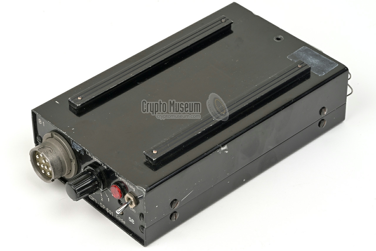
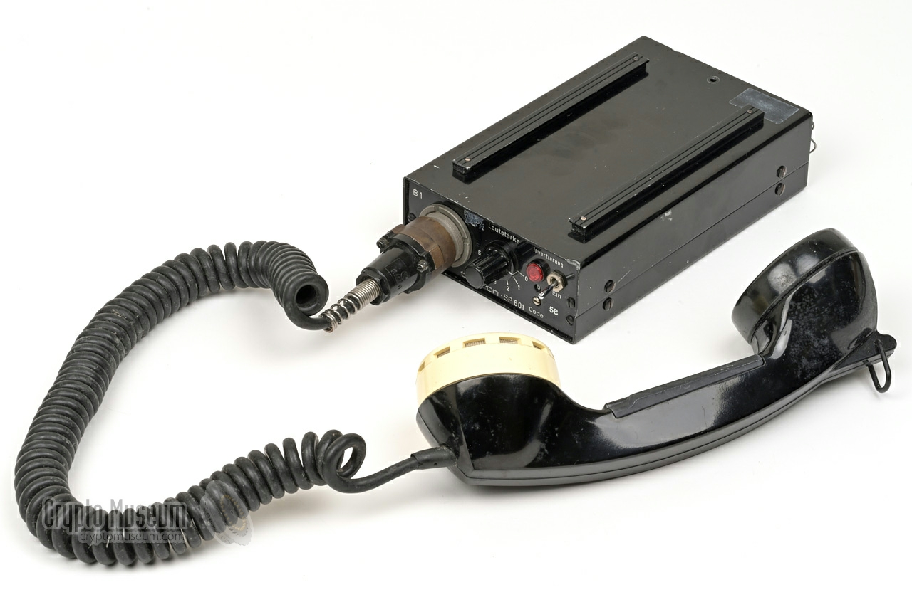
The image on the right shows a typical SP-601. It is housed in an aluminium
enclosure with two rigs at the top, allowing it to be mounted in a vehicle
bracket. Radio and power are wired at the rear. The handset is connected
at the front.
Unlike later voice scramblers, which used a single-chip solution, the SP-601
is built with discrete components, spread over two PCBs.
Generally speaking, voice scrambling is not (and never was) very secure.
An eavesdropper can simply reverse the audio spectrum once again,
to make the secret conversation intelligible again.
|
|
|
|
With just 6 available codes — the frequency mirroring points — an eavesdropper
has little trouble finding the correct one. In fact, in the days when
police scanners
were popular, some listeners got so experienced that after a while
their brain would 'translate' the scrambled speech 'on the fly' without any
technical means. The SP-601 was succeeded by the SP-612 which was based on a
single-chip solution and offered 16 scrambling codes, but was nevertheless
inherently insecure.
|
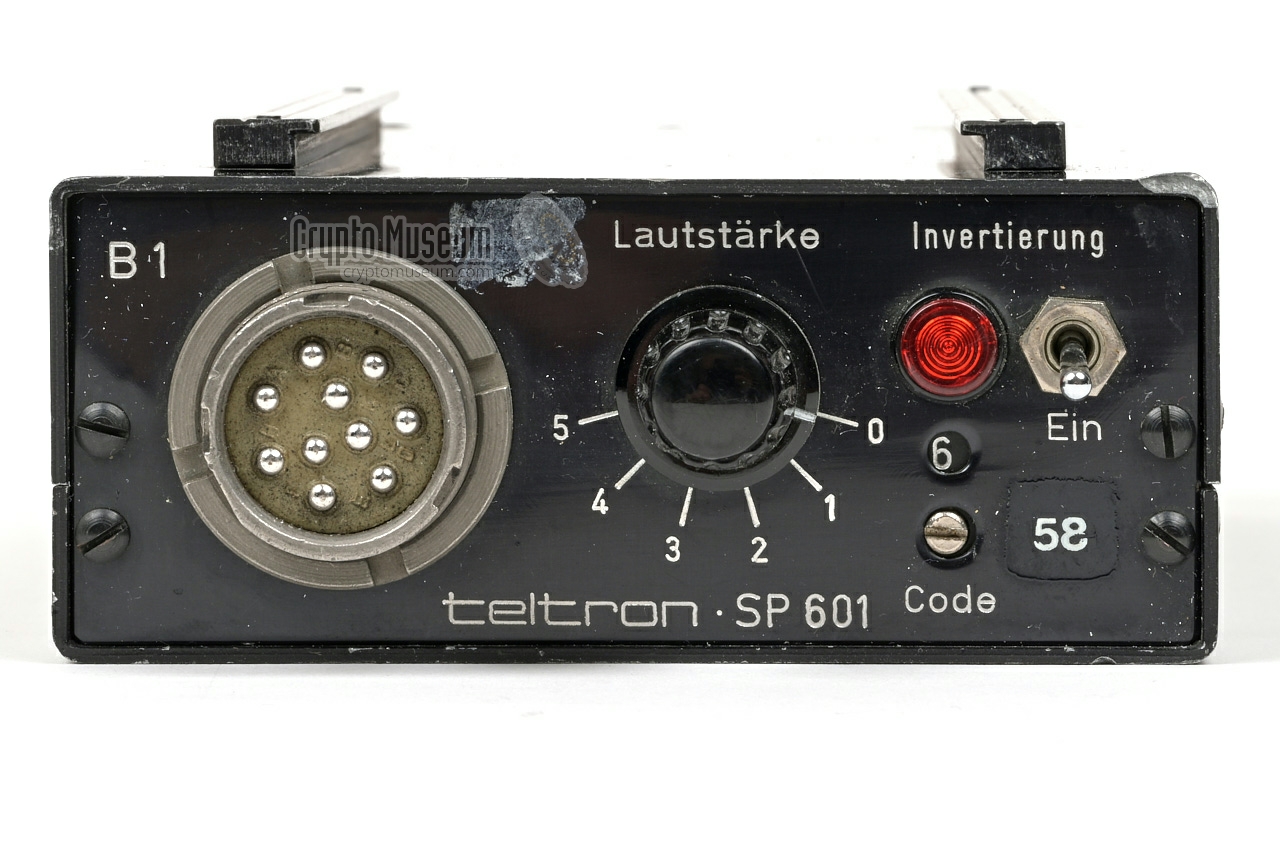
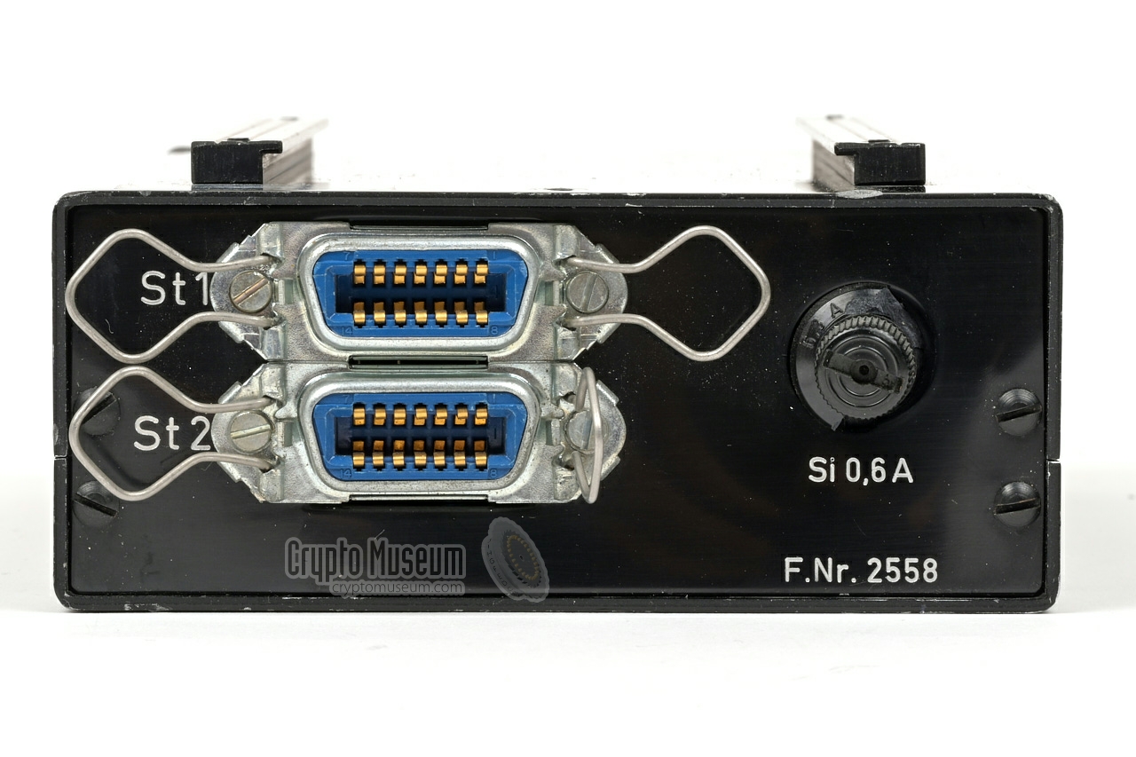
The image below shows the front panel of the SP-601. At the left is the
rather large U79/U socket for connection of a handset with integrated
push-to-talk (PTT) switch. This was the standard socket used by the German
emergency services (BOS) at the time. To its right is the Volume knob.
At the top right is a switch to enable the frequency inverter, with an
indicator lamp showing that it is active. At the bottom right is a recessed
screw that allows the selection of the desired mirroring code (1-6), using
a screwdriver.
On the device shown here, mirroring code 6 is selected.
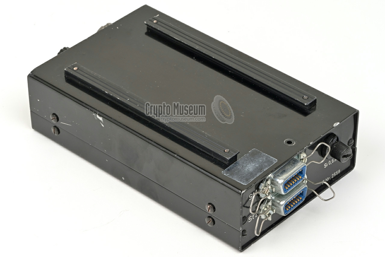
The wiring to the radio, a 12V DC power source, an external speaker,
and an (optional) external inversion switch, is connected at the rear.
There are two sockets (St1 and St2) that are wired in parallel.
St1 is intended for connection to the radio, whilst St2 is used for
the remaining wiring.
St1 was usually connected to a standard BOS 2-way radio, such as the
Telefunken FuG7b or FuG8.
The lower socket (St2) was intended for connection to the battery of the
vehicle. It also has contacts for connection of an external speaker and an
extra swtich to enable voice inversion remotely.
At the far right is a 200 mA fuse that
protects the 12V DC power supply to the device.
|
|
The principle of the SP-601 is based on mirroring of the frequency spectrum
around a single spot frequency f c somewhere in the middle of the audio spectrum.
This method is also known as frequency inversion. Low
tones become high tones and vice versa, as shown in the diagrams below.
The audio spectrum of the voice data (1) is mixed with a fixed
carrier frequency f c (2).
This results in two spectra: one that is the sum
of the original sectrum and the carrier (3),
and one that is the difference of the two signals (4).
A low-pass filter (LPF) is then applied to filter-off the
sum and leave only the difference, effectively resulting in a mirrored
audio band (5).
At the receiving end, this process of mirroring of the spectrum is repeated
to make the speech 'legible' again:
The position of the carrier frequency f c
can be shifted somewhat, in order to obtain mutiple 'codes'.
In the SP-601, six such 'codes' are available, corresponding to an
f c of 2000 Hz, 2100 Hz, 2200 Hz, 2300 Hz, 2400 Hz or 2500 Hz,
selectable with a rotary switch at the front panel.
The advantage of this technique is that it completely takes place within the
audio bandwidth of a channel, whereas digital encryption generally requires
more space. This allows scrambling to be used in existing systems.
At the time, scramblers were also cheaper than
digital encryptors, which is why scramblers were used by the police
in many countries from the 1970's well into the 1990's.
The disadvantage of this method is that an evesdropper can easily reverse
the mirroring process with a simple electronic circuit.
In addition, experienced listeners could sometimes even extract useful
information from the seemingly garbled speech directly, without a descrambling
circuit.
|
|
All wiring to the radio, car battery, external speaker and inversion
remote control are at the rear of the device, in the form of two 14-pin
Amphenol sockets (St1 and St2). Note that for convenience, St1 and St2
are fully wired in parallel. Below is the pinout when looking into the sockets.
Also note that the following pin-pairs are interconnected:
1+8, 3+4, 5+12 and 7+14.
|
ESP External speaker 4Ω 1.5W GND Signal ground n.c. not connected n.c. (wired to 3) GND Power ground (0V) PTT Push-to-talk BAT +12V to +17V DC source ESP (wired to 1) INV Inversion on (when grounded) MIC Microphone input (from radio) SPK Speaker output (to radio) GND (wired to 5) EXT Power from radio 1 BAT (wired to 7)
|
|
-
If power is taken from the connected radio (on pin 13)
rather than directly from the car battery,
pin 13 must be connected to pins 7 and 14.
|
-
Documentation kindly supplied by Jim Meyer [1].
|
|
|
|
Any links shown in red are currently unavailable.
If you like the information on this website, why not make a donation?
© Crypto Museum. Created: Thursday 09 July 2015. Last changed: Friday, 09 January 2026 - 14:36 CET.
|
 |

|
|
|