|
|
|
|
|

|
|
Phone Telsey TDS-2004M → ← TDS-2003
Telephone voice encryptor
The TDS-2004 was a speech encryption device for use on analogue (PSTN)
telephone networks, introduced by Telsy in Turin (Italy)
around 1981. It was part of the TDS-2000
family and is the table-top version of the TDS-2004M.
It is also compatible with the TDS-2003 briefcase unit.
The TDS-2004 was also sold as an OEM product by
Gretag in Switzerland as the
Gretacoder 103,
and by Teltron in München (Germany)
as TVC-9004 and TVC-9004QD (with quasi-duplex operation).
|
The TDS-2004 was the office version of the TDS-2004M
mobile encryption device. It was based on the same electronics and was housed
in a dark green metal case.
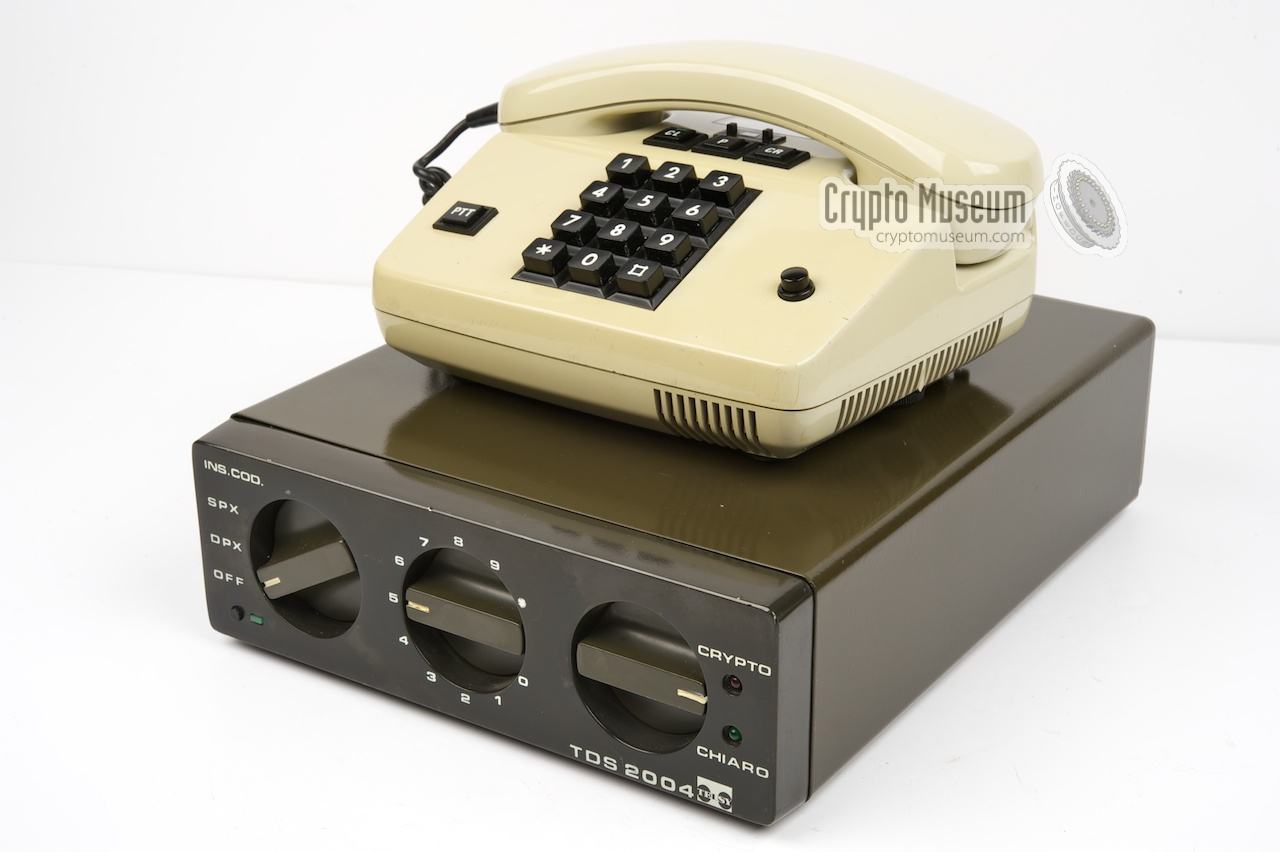
The image on the right shows a typical TDS-2004,
with the D-2000 companion telephone placed on top.
The TDS-2004 has two modes of encryption: time division or
2-dimensional coding (time and frequency division), and the cryptographic key
determines which mode is used.
A total of 9 keys can be preset and the key selector at the front is used to
select the key compartment.
|
|
|
The TDS-2004 consists of two units:
the main TDS-2004 unit and a separate
modified D-2000 telephone set. The two are
connected via a 1.5 meter long cable that is fixed to the telephone set.
The other end has a DB25 male plug that mates with a socket at the rear of
the TDS-2004.
|
The image on the right shows the D-2000 telephone set, which is in fact
a modified Krone FeTAp 752. This telephone was one of the commonly used
models in Germany during the 1980s. Although the phone has push-buttons
for dialling a number, it only features pulse-dialling, as the majority of
exhanges in the 1980s did not support tone dialling (DTMF).
Extra buttons are added to this telephone to allow switching between
clear (CL), crypto (CR) and private mode (P).
The Push-to-Talk switch (PTT, left) is only used in half-duplex mode.
|
|
|
Once the crypto keys are loaded into the main unit, the user can control
all features from the telephone set.
A call is initiated en clair, which is indicated by a RED LED in the
CL-button. Once the call has been established, one of the parties presses the
CR-button in order to go secure. If it fails, an alarm will be sounded.
Otherwise the CR-LED will be lit.
The TDS-2000 range appeared to be very successful and thousands of units were
sold to the Army, the Police and even to the corporate sector.
As a result, the TDS-2004 remained in production well into the 1990s.
|
Setting the key can be done on the front panel.
When setting the key, the mode selector (left) has to be set to SET KEY
(INS COD). Then set the key selector (centre) to the number of the required
key compartment and toggle the right knob to CLEAR (CHIARO) in order to
purge the current key.
Next, enter between 1 and 8 digits, by rotating the
key selector to the required number and toggling the right knob to
CRYPTO in order to enter the digit.
When doing this, you need to remember which digits you have already entered.
The TDS-2004 does not have the visual aid of a display, like the
TDS-2003.
Finally, set the mode selector to SPX (simplex) or DPX (duplex).
|
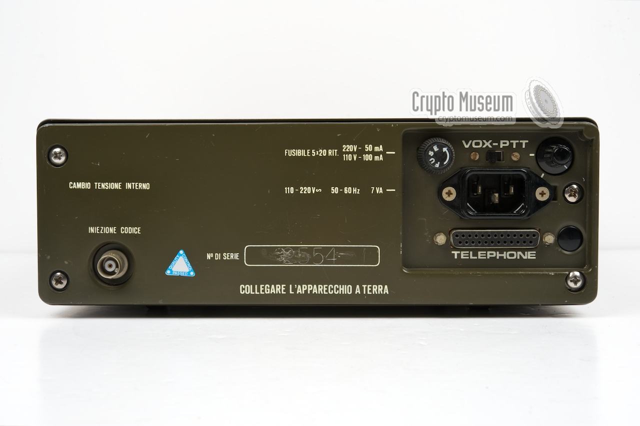
All connections between the D-2000 telephone and the TDS-2004 main unit,
are via a single DB25 female socket at the rear of the TDS-2004. The D-2000
has a fixed 1.5 meter cable with a DB25 male plug at the end. The pin-out
of the DB25 socket is given below:
Some of these lines are optional, such as the remote key-selection
(BCD-switch) that is shown at the bottom. It is mounted at the top of
the D-2000.
The PTT-switch could also be mounted in the handset.
The off-hook switch (pin 22) is only needed when automatic line-sensing
is disabled.
|
|
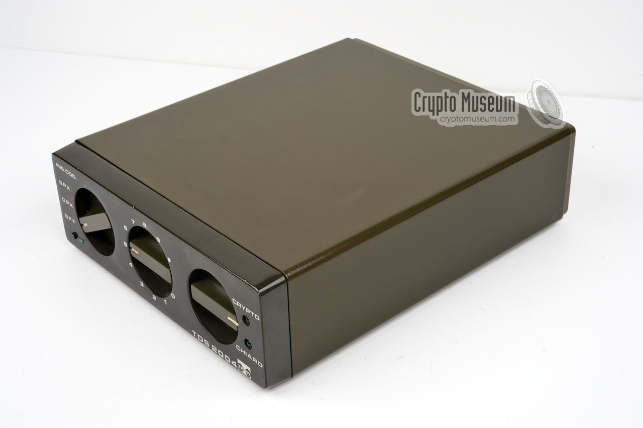
The TDS-2004 is housed in a sturdy metal case with a die-cast aluminium frame
holding the main circuit boards. The hull of the case can easily be removed
by releasing 4 large bolts at the bottom. The frame is attached to the
front panel that also holds a small PCB with the controls.
The unit is extremely service friendly and can be repaired within minutes
by swapping boards.
|
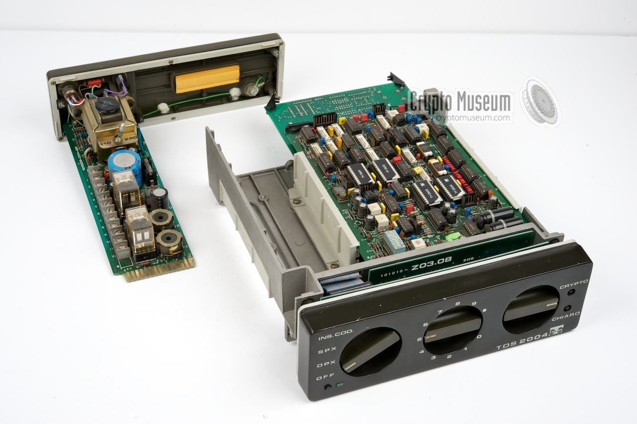
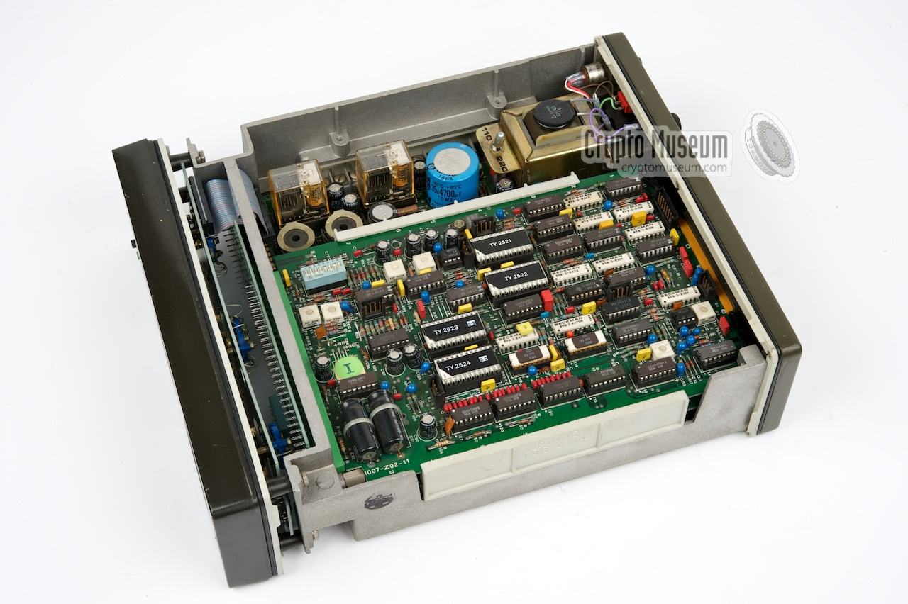
The TDS-2004 contains two main PCBs mounted in the frame, and a
removable power supply unit (PSU).
The image on the right shows the main boards (right)
and the separated PSU (left).
The PSU also holds the DB25 socket for the phone.
The two main boards can be retracted
from the frame towards the rear.
The upper board holds the analogue
circuitry, whilst the lower board
contains the digital circuits.
These two PCBs are identical to the boards used in the
TDS-2004M
and the TDS-2003.
The only difference between the three models is in fact the interface.
|
|
|
The digital board contains a Z-80 microprocessor plus a number of custom chips,
manufactured American Microsysstems Inc. (AMI) in their production facility in
Austria. The analogue board also contains some custom-designed active
low-pass filters, which are implemented as thick-film circuits in the
black/white chips. All custom chips have numbers starting with 'TY'.
At the heart of the analogue board are two FX-309
Delta Modulators by CML (UK) [3]. For a more detailed description of the two
boards, please refer to the description of the interior of the
TDS-2004M.
|
- Telsy S.p.A., TDS 2004 - THANKS !
Device featured on this page kindly donated by Telsy.
April 2012.
- Telsy S.p.A., TDS 2004 Instruction Manual
June 1981.
- Consumer Microcircuits Ltd., FX-309 Datasheet
Continuous Variable Slope Delta Modulator (CVSD).
Date unknown. Retrieved February 2012.
|
|
|
|
Any links shown in red are currently unavailable.
If you like the information on this website, why not make a donation?
© Crypto Museum. Created: Wednesday 02 May 2012. Last changed: Wednesday, 21 August 2024 - 07:29 CET.
|
 |

|
|
|