|
|
|
|
|

|
|
Phone Telsey TDS-2004 →
Portable telephone encryptor
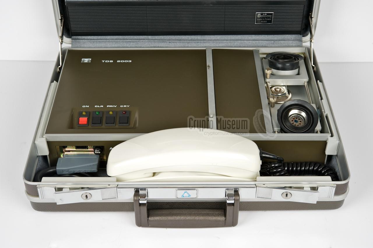
The TDS-2003 was a portable telephone encryption device, introduced by
Telsy in Turin (Italy) around 1980. It was built inside a
standard Delsey briefcase and was part of the TDS-2000 series.
It featues two-dimensional encryption based on a
time and frequency domain speech scrambler.
The device was also sold as an OEM product by
Teltron in München (Germany) as the TVC-9003.
|
The TDS-2003 followed hot on the heels of the compatible
TDS-2004
and TDS-2004M that were introduced a few years earlier.
The TDS-2000 range appeared to be extremely successful and thousands of
units were sold to the Army, the Police and even to the corporate sector.
They remained in production well into the 1990s.
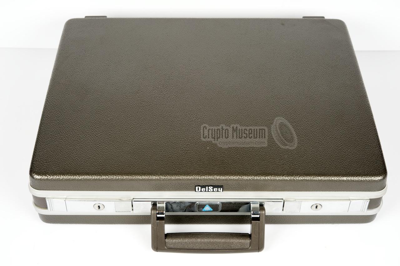
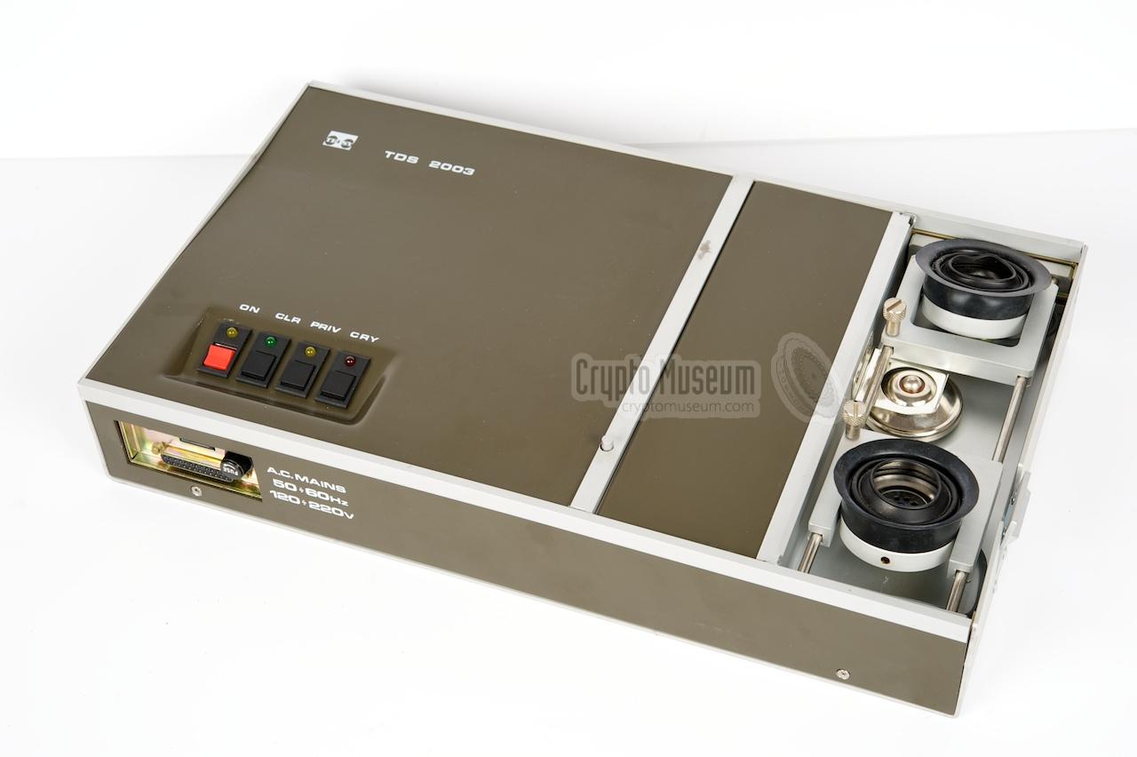
The image on the right shows a typical TDS-2003 built inside a
Delsey briefcase
that was commonly used by business men in those days.
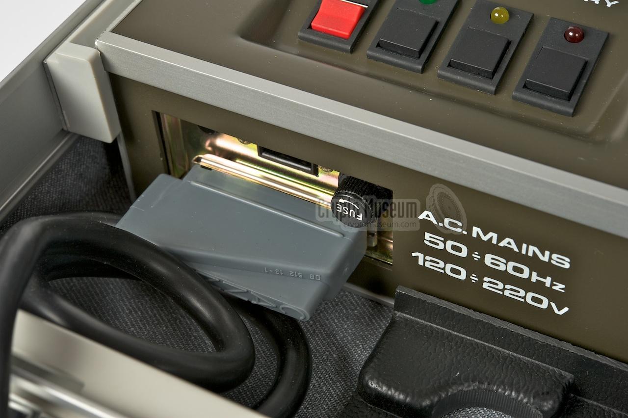
The unit is powered from the mains which is connected to a socket
at the front left.
|
|
|
The TDS-2003 can be connected directly to an analogue telephone line (PSTN),
using one of the supplied cables. If a direct line is not available, it can
also be used with the built-in acoustic coupler at the right. In that case,
an external phone is used as the interface to the PTT line.
|
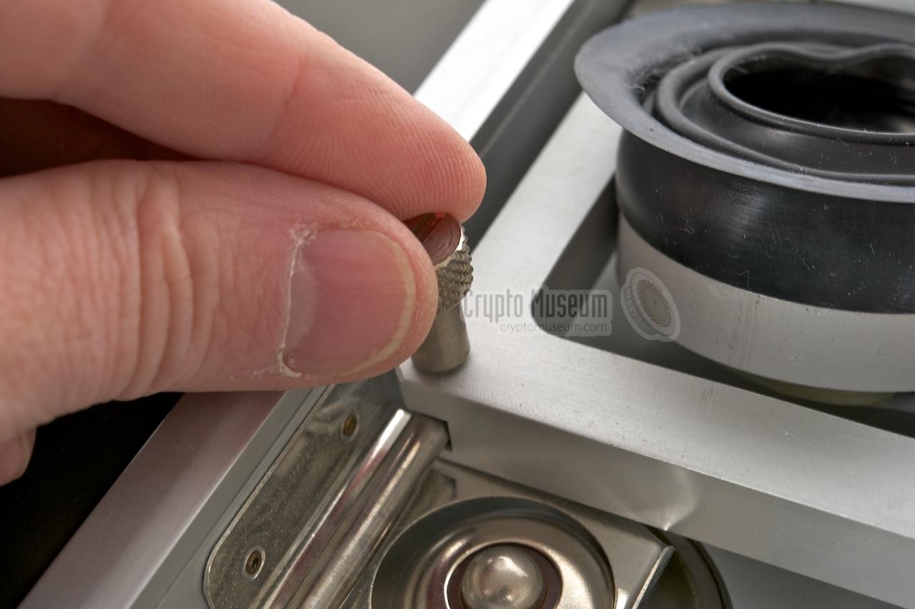
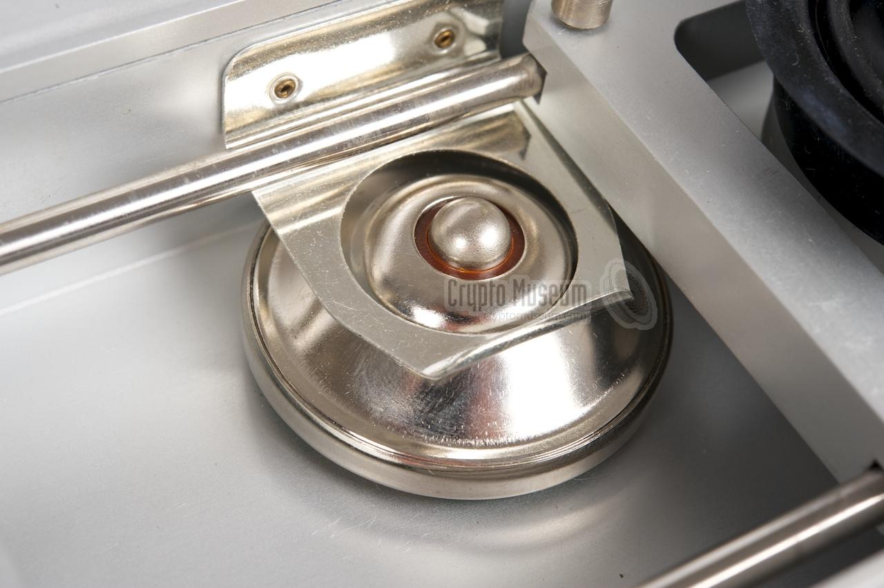
The image on the right shows the acoustic coupler in use.
The handset of a domestic telephone set is placed over the two rubber pads
of the coupler. The transmitter and receiver of the coupler
can be adjusted
to accomodate virtually any handset, such as this one.
In front of the encryptor is a built-in handset that is used for the
voice conversation. It is connected to the main unit via a
DB25 socket
at the front left. The handset can also be placed
outside the briefcase
and has a dial
that is used when the unit is connected directly to the line.
|
|
|
Hidden inside the acoustic coupler – stowed under a bracket – is a
spare microphone of the type that was
commonly used in domestic telephone sets at the time. It allowed the
microphone of the telephone set in, say, a hotel room to be replaced,
just in case it was bugged.
Although this may seem far fetched,
telephone bugs like the TM-106
were quite frequently used back
then.
|
|
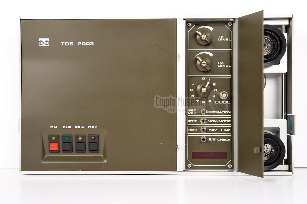
Operation of the TDS-2003 is rather straight forward. It is similar to
controlling the TDS-2004M, but has the added advantage
of a LED display for monitoring the input. The device has 9 key compartments,
allowing 9 different keys to be stored in advance. When the unit is switched
off, the keys are retained in memory by an
backup battery
that is mounted on the digital board.
|
At the center of the control panel is the CODE selector. It is a 11-position
switch, marked with the numbers 0-9 and '*'. Position 0 is for private
communication, whilst 1-9 are used for the key compartments.
In case security is compromized, they can be purged (ZEROIZED) by setting
the key dial to the *-position and pressing CLR.
Loading a valid key into a key compartment involves the selector to be set to
the appropriate number, pressing of the CLR-button (to erase any previous key)
and entering a number between 0 and 99 999 999 (1 to 8 digits).
|
|
|
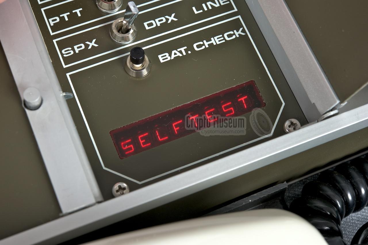
Entering a digit is done by setting the selector to the desired
number and pressing CRY.
The image above shows the 8-position alpha-numerical LED display
when entering the cryptographic key for key compartment 1.
The first digit determines the encryption mode: 1-5 is used to select
time division only,
whilst 6-9 selects 2-dimensional coding
(time and frequency division) [2].
To the right of the key selector is a BNC-socket that allows an external
key-filler to be connected. The key-filler was used for automated loading
of the valid keys without the need to follow the above procedure.
It minimizes errors when settings the keys and helps keeping the keys
secret.
|
|
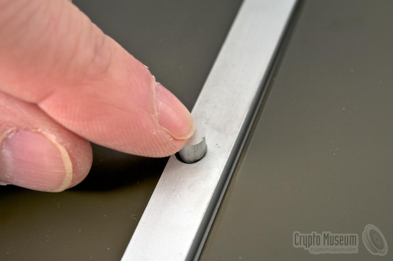
The TDS-2003 is easily removed from the briefcase by releasing a lock
at the right. The entire unit
can then be lifted out and placed on the table.
The interior of the device
is accessible by removing a few bolts from the front and the sides,
and then removing the cover.
|
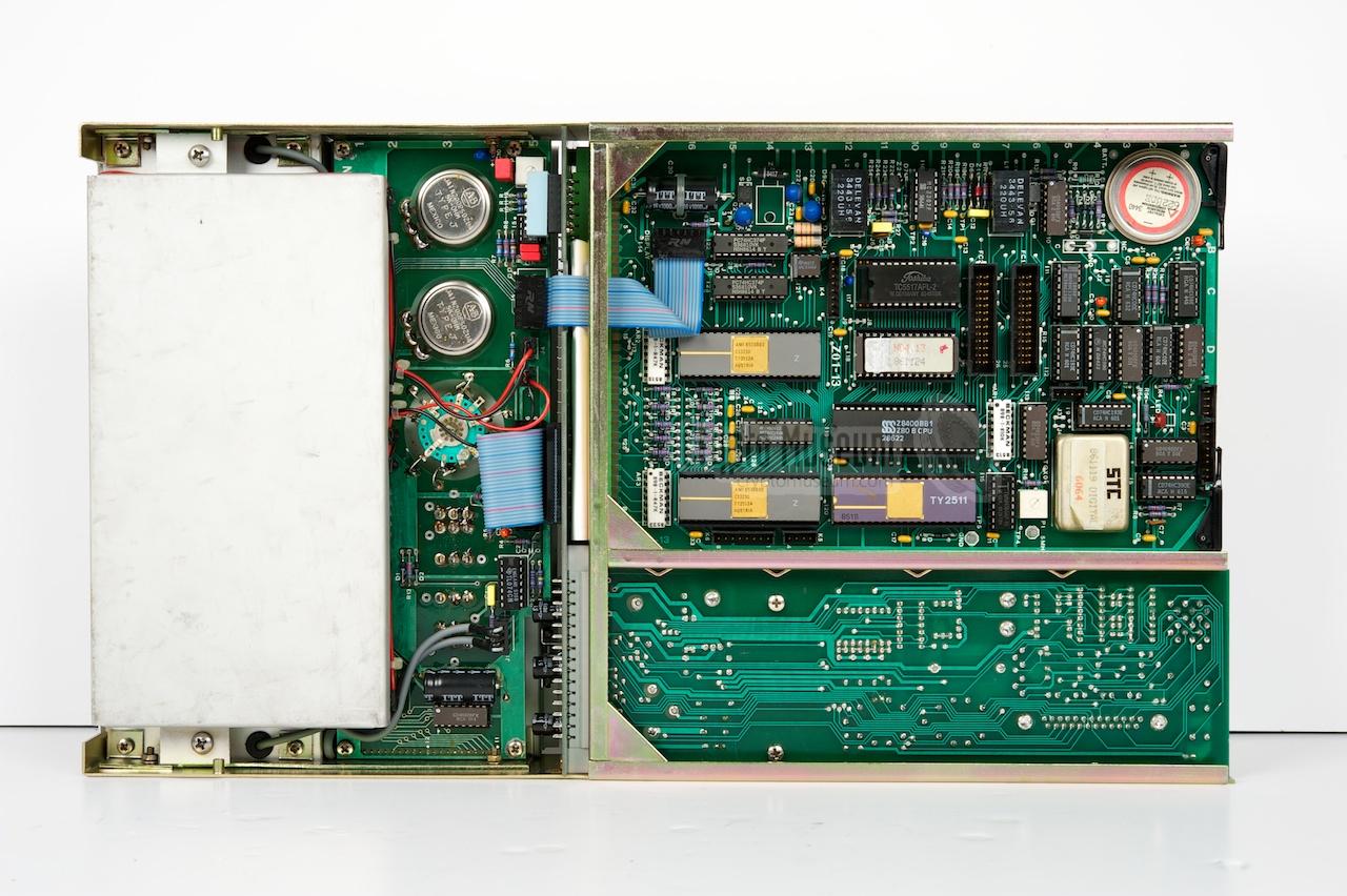
The TDS-2003 is based on the same electronic design as the TDS-2004.
At the heart of the TDS-2003 are the same two PCBs with the analogue and
the digital circuitry. These are accompanied by a built-in mains power
supply, the control panel and the acoustic coupler.
The image on the right shows the analogue board which becomes visible when
the top cover is removed. It is identical to the analogue board of the
TDS-2004 and is inserted from the left into a PCB
socket. At the front left of the unit is the
power supply (PSU).
|
|
|
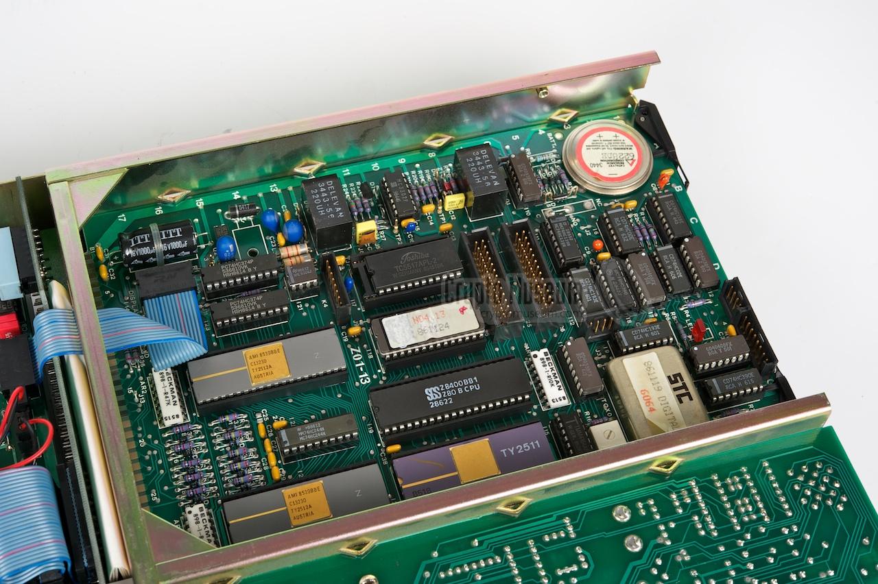
The digital board is located at the
bottom,
just below the analogue board. It is also slotted-in from the left and connects
to the rest of the electronics via a card-edge connector. Also at the bottom
is the control panel and the acoustic coupler.
For a more detailed description of the analogue and digital boards, please
refer to the description of the TDS-2004M.
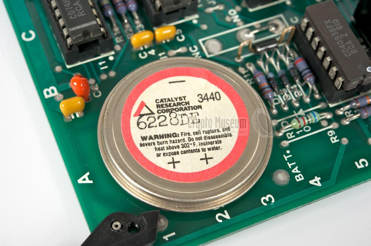
When we received the TDS-2004M
we discovered that the internal backup battery had seriously damaged the
interior. After many years of storage, the battery had desintegrated and its
contents had damaged various tracks and components on the PCB.
So, when we received the TDS-2003 [1] we immediately opened it in order to
removed the backup battery. Luckily, the battery
in this device was of another brand (Catalyst) and type (3440) and was still fully functional.
Although it was installed in 1987, this Lithium-Iodine cell
still supplied its nominal voltage of 2.8V.
|
|
|
|
Any links shown in red are currently unavailable.
If you like the information on this website, why not make a donation?
© Crypto Museum. Created: Wednesday 29 February 2012. Last changed: Wednesday, 21 August 2024 - 07:38 CET.
|
 |

|
|
|