|
|
|
|
|

|
|
← Tadiran Voice
Voice crypto unit
The SEC-13 was a voice crypto system developed in the mid-1970s
by Tadiran in Israel.
It was intended for use in combination with existing radio networks, such
as Clansman and
the American VRC-12 series radios.
It was built according to specifications layed out by the
IDF (Israel Defense Forces), but was also used by a number of NATO countries.
Due to its shape and connector at the rear, the unit fits in the same space
as an R-442 receiver.
|
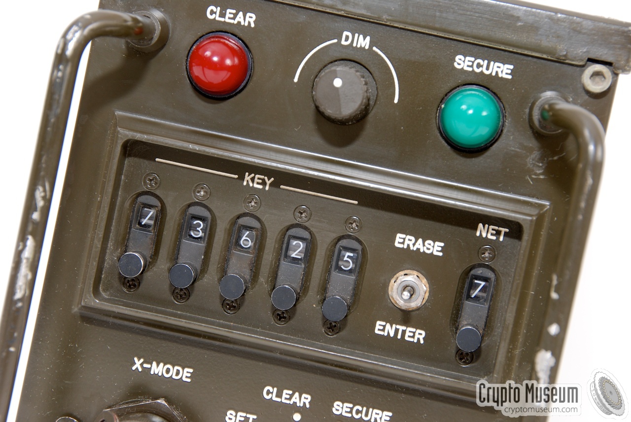
The image on the right shows a typical SEC-13 crypto unit.
It is easily recognised by the rather large red CLEAR
and green SECURE lamps on the upper part of the
front panel.
Immediately below the lamps is the selection of the key and the appropriate
(radio) net.
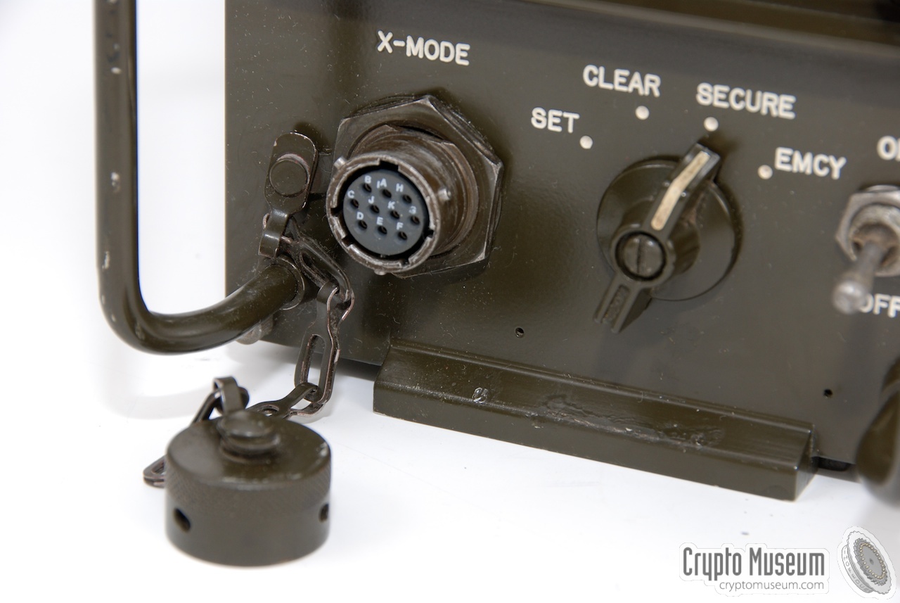
At the bottom of the front panel is the X-MODE connector
(see below),
the MODE-selector and the power switch (ON/OFF).
The MODE-selector is used for selection between CLEAR and SECURE and to
enter the keys.
More detailed images of the front panel below.
|
|
|
At present, no further information about this crypto unit is known.
A slightly later version, the SEC-15,
features both voice and data encryption.
It is clear that they were scheduled to be replaced from 1995 onwards,
by more modern equipment such as the
SINCGARS radios.
Nevertheless, they remained in service well into the 2000s.
Although they were used until recently, they sometimes show up on the
European surplus market, which is also where the unit shown here was found.
If you have additional information about any of the Tadiran crypto devices,
please contact us.
|
|
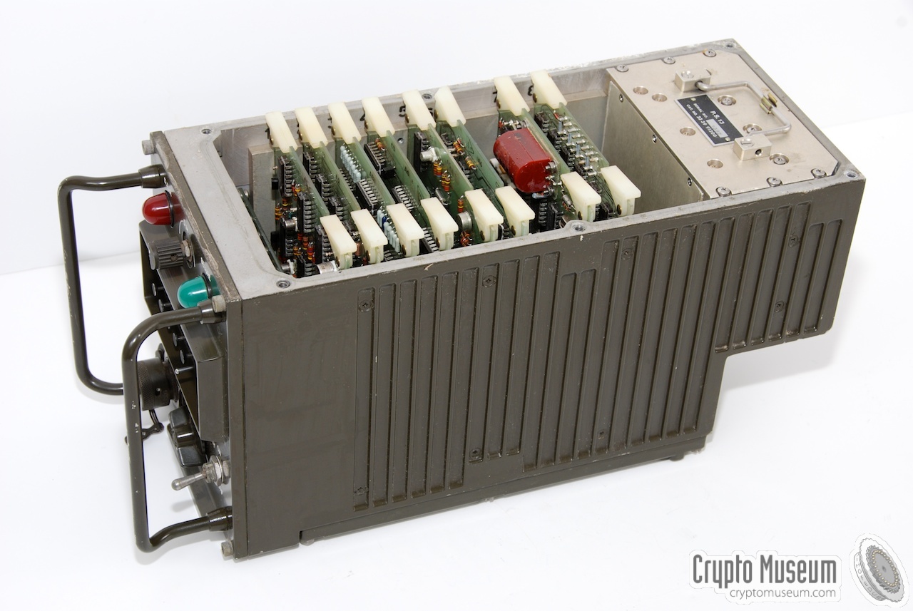
The interior of the SEC-13 is easily accessible and gives a lot of information
about the state-of-technology when the unit was developed. It also tells us
approximately when the unit was produced. After removing the 6 bolts from the
top lid, the interior is revealed.
|
The unit consists of 8 printed circuit boards (PCBs), numbered 1 thru 8,
and a power supply unit (PSU). The PCBs are all slotted into a so-called
backplane that resides at the bottom of the unit.
The main connector, the front panel and PSU are all connected to the backplane.
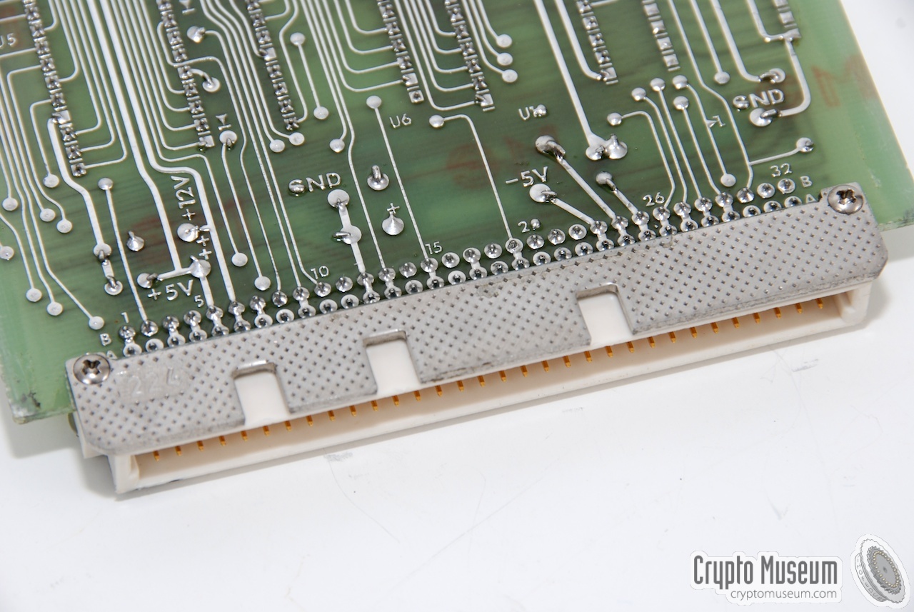
Each of the PCBs can easily be removed, by tilting the white levers and lifting
it out of its bay. Each PCB has an index key mounted to its main
connector, to prevent it from being inserted into the wrong slot. Please check the
rightmost image below for a close-up.
|
|
|
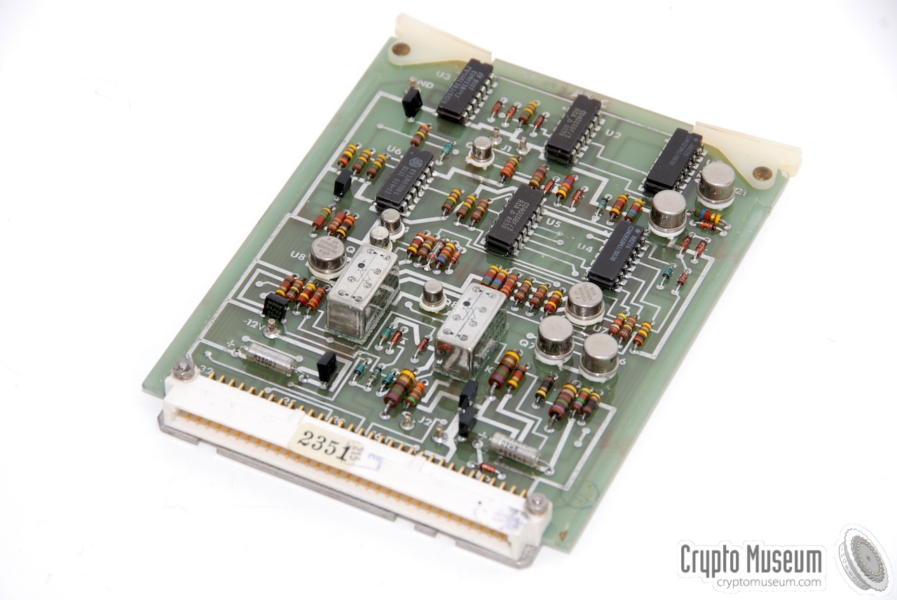
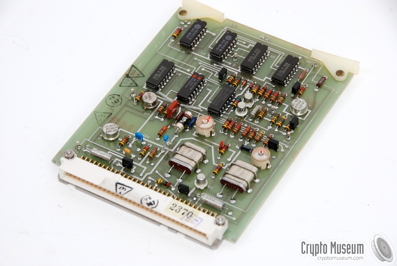
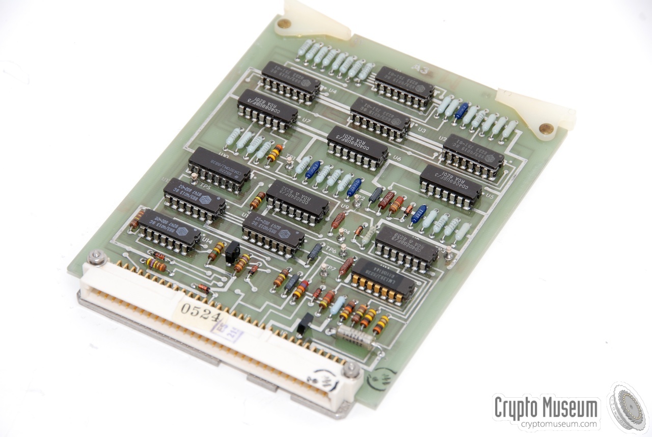
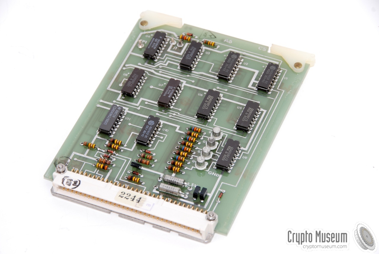
Hi-res photographs of each of the 8 PCBs are available in the second row of
images below. Most of the PCBs carry analog circuits and interfacing beween
the analog and digital parts (I/O). PBC A7 contains the processor (CPU)
and is described in more detail below. The last board (A8) contains a large number of 4015 shift-registers and was probably the cipher board.
|
|
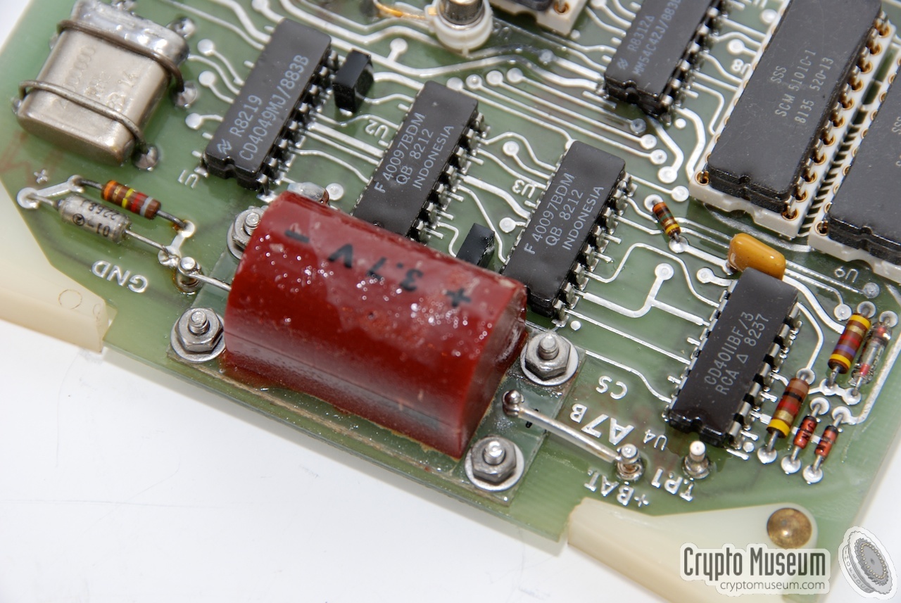
The PCB marked as A8 contains the Central Processing Unit (CPU).
It is built around a Fairschild 3850 processor, which is basically a dual
chip F8, running at 2MHz.
Next to the PCB is the 3853 static RAM controller that acts as an interface
between the 3850 processor and the 256 byte RAM (Random Access Memory,
2 x SCM5101, 4 bits each).
|
The image on the right shows the major components of the A8 board.
The 3850 processor is the large 40-pin chip at the top. The 3853
RAM controller is immediately below it.
The firmware is stored in a 1KB 2708 EPROM (the IC with he golden cap and the
window).
The two identical ICs at the bottom are the static RAMs. A 3.7V battery at
the left ensures the information stored in RAM is retained
when the unit is powered off.
When crypto-security is compromised, the ERASE switch at the front is used
to wipe the RAM contents (crypto keys).
|
|
|
The production dates on the various electronic components inside the SEC-13
vary between 1978 and 1983, suggesting that the unit was designed in the late
1970s and brought to market in the early 1980s.
A detailed search for foreign (non-US) crypto-equipment, carried out
by the Cyberspace Policy Institute of the George Washington University, lists
the Tadiran SEC-13,
SEC-15
and SEC-22 as in-use in 1999.
They were probably used well into the 2000s.
|
|
The X-MODE connector at the front of the SEC-13 allows the unit
to be connected directly to the 10-way X-MODE connector of the
VRC-12 series radio sets. The expression X-MODE is generally
used for the connection of security devices.
|
On the VRC-12 series radio sets, this 10-way connector is wired
as follows [2]:
A. X-MODE in (RX)
B. n.c.
C. X-MODE out (RX)
D. TONE in (150 Hz)
E. X-MODE in (TX)
F. GND
G. X-MODE out (TX)
H. n.c.
J. TONE out (150 Hz)
K. PTT
|
|
|
The X-MODE connector on the VRC-12 series radio sets
was meant for the connection of equipment for secure voice
communication. This included the Nestor
KY-8,
the KY-28,
the KY-38
and the SEC-13.
It was also compatible with later - more advanced -
voice encryption units, such as the VINSON KY-57
and, with the proper junction box, the KY-99.
When no crypto unit is connected to the radio, a terminator cap has
to be used at the radio-end instead. It contains 3 shorting wires:
between A-C (RX), D-J (TONE) and E-G (TX).
|
The SEC-13 has no provisions for the connection of an external
key filler
like the later KY-57
and the KY-99.
Therefore the message key has to be set up manually,
using the numerical push-buttons on the front panel.
Once the correct number was setup, the user had to toggle the
ENTER switch in order to load the 5-digit key into memory.
Once the key was entered, the user would reset all of the 5
push-buttons to zero, so as not to reveal (part of) the
message key in case of a compromise.
When cipher security was compromised, the user only had to
push-up the ERASE switch in order to wipe the contents of
the battery-backed RAM and, hence, the message keys.
|
|
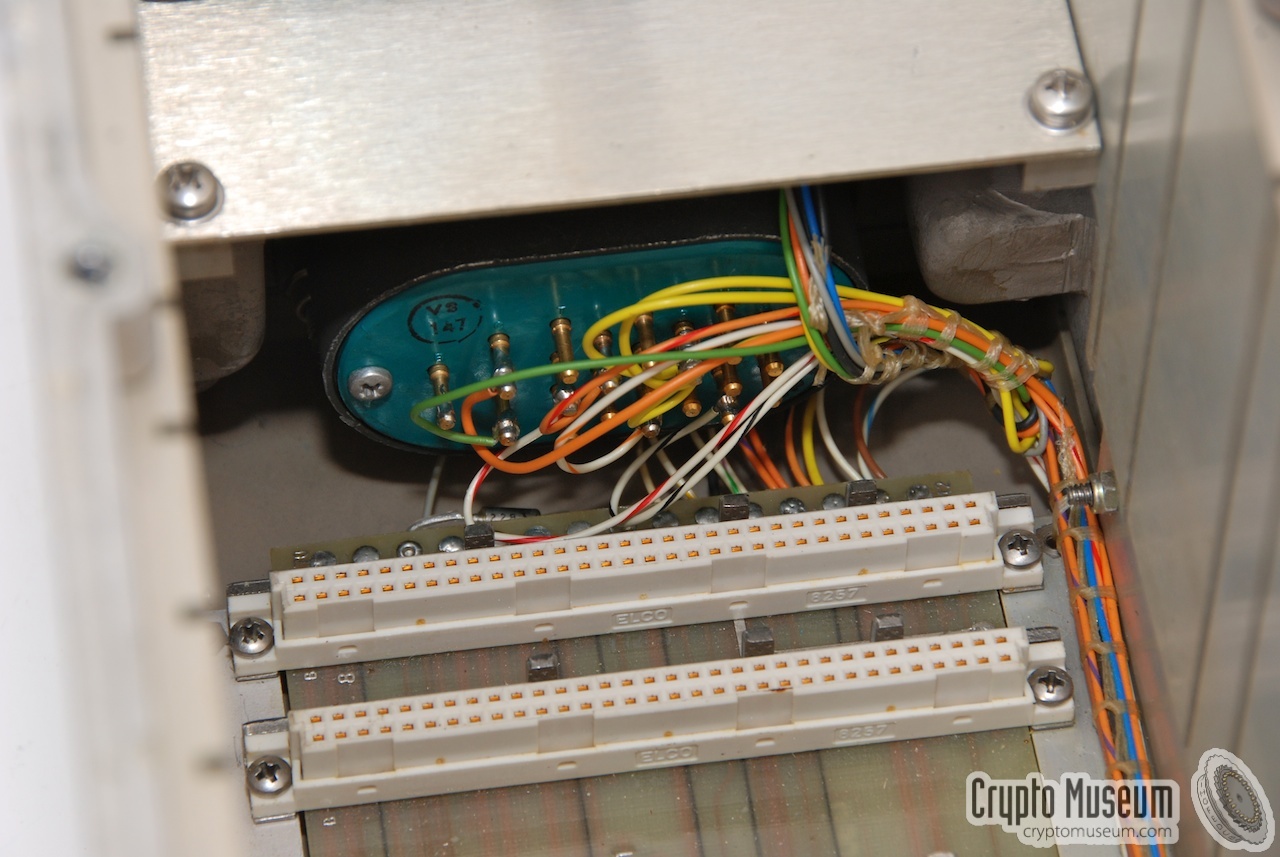
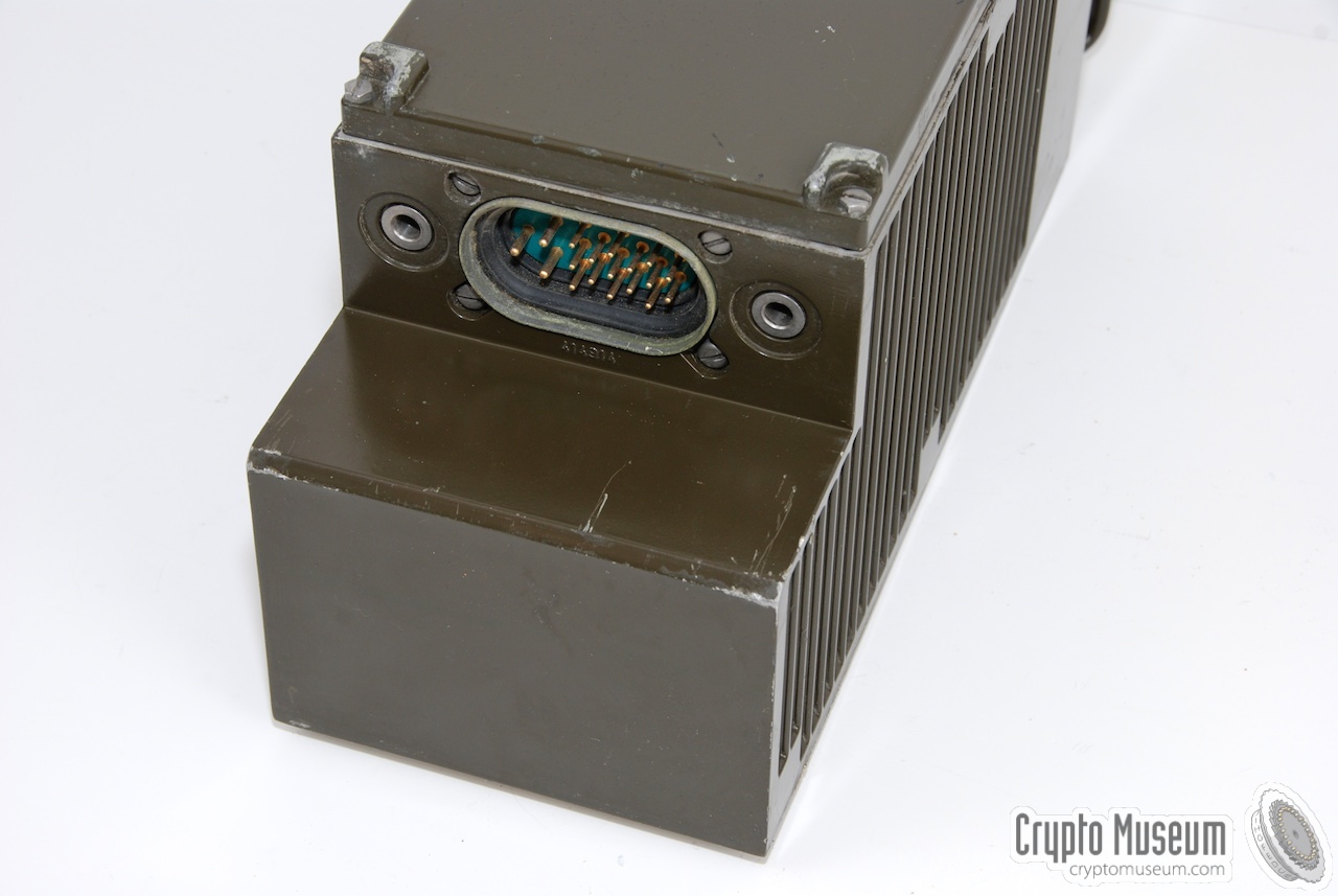
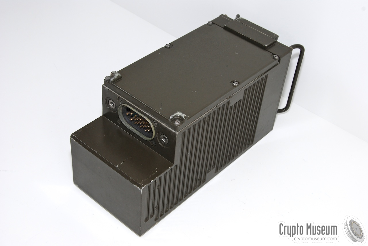
The form factor and shape of the SEC-13 case,
and the main connector at the rear,
are identical to those of the auxiliary R-442 receiver.
This suggests that the SEC-13 could
be slotted into a standard American VRC rack mount.
|
The image on the right shows the typical 18-pin connector that is available
at the rear of the unit (here seen from the bottom).
At present, the layout of this connector is unknown to us.
Check the images below for further details of this connector.
The rightmost one shows the solder-side of the connector, seen from the
interior of the SEC-13.
|
|
|
|
|
|
Any links shown in red are currently unavailable.
If you like the information on this website, why not make a donation?
© Crypto Museum. Created: Saturday 22 May 2010. Last changed: Tuesday, 30 April 2024 - 17:12 CET.
|
 |

|
|
|