|
|
|
|
|

|
|
ELCRO Siemens Voice Germany Elcrovox 1/4 →
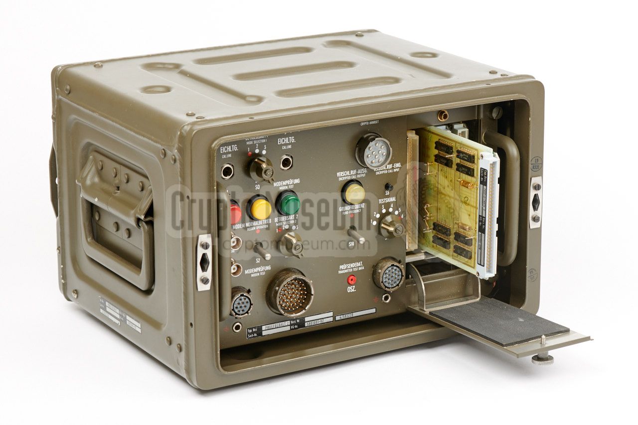
The device is approx. 19" wide and is housed in an olive green aluminium
transport case, from within it is operated. Controls and connections
are at the front. At the centre is a locked hinged door behind which the
KEY material is installed.
The image on the right shows an typical Elcrovox 1/3, from the
collection of the Museum for Telecommunication in Frankfurt (Germany)
[1].
The device was used in many NATO countries, such as Germany, the Netherlands
and also in Canada. According to the US, it's quality was comparable
to the NSA-developed
STU-II voice encryptor
[3].
|
|
|
The problem with the Elcrovox 1/3 however, is that it is not interoperable
with the STU-II and other voice encryption
products that use the secret NSA/GCHQ
encryption algorithm SAVILLE,
which limits its usability. This problem was solved in March
1983, with a bi-lateral arrangement, that allowed Germany to develop its own
STU-II compatible products, just like
Philips Usfa
had done a few years earlier
[3]. It resulted in the development of the backward compatible
Elcrovox 1/4 which was fully interoperable with the
STU-II and compatible products like the
Spendex-40.
|
|
Before the Elcrovox can be used, a suitable key has to be installed in
the device. This is done by placing two pieces of punched paper tape in
the tape reader, or scanner, that is present behind a locked door at
the centre of the device. The two paper strips are prepaired in
advanced by the German BSI,
and contain the cryptographic key.
In practice, the key was renewed every 24 hours.
|
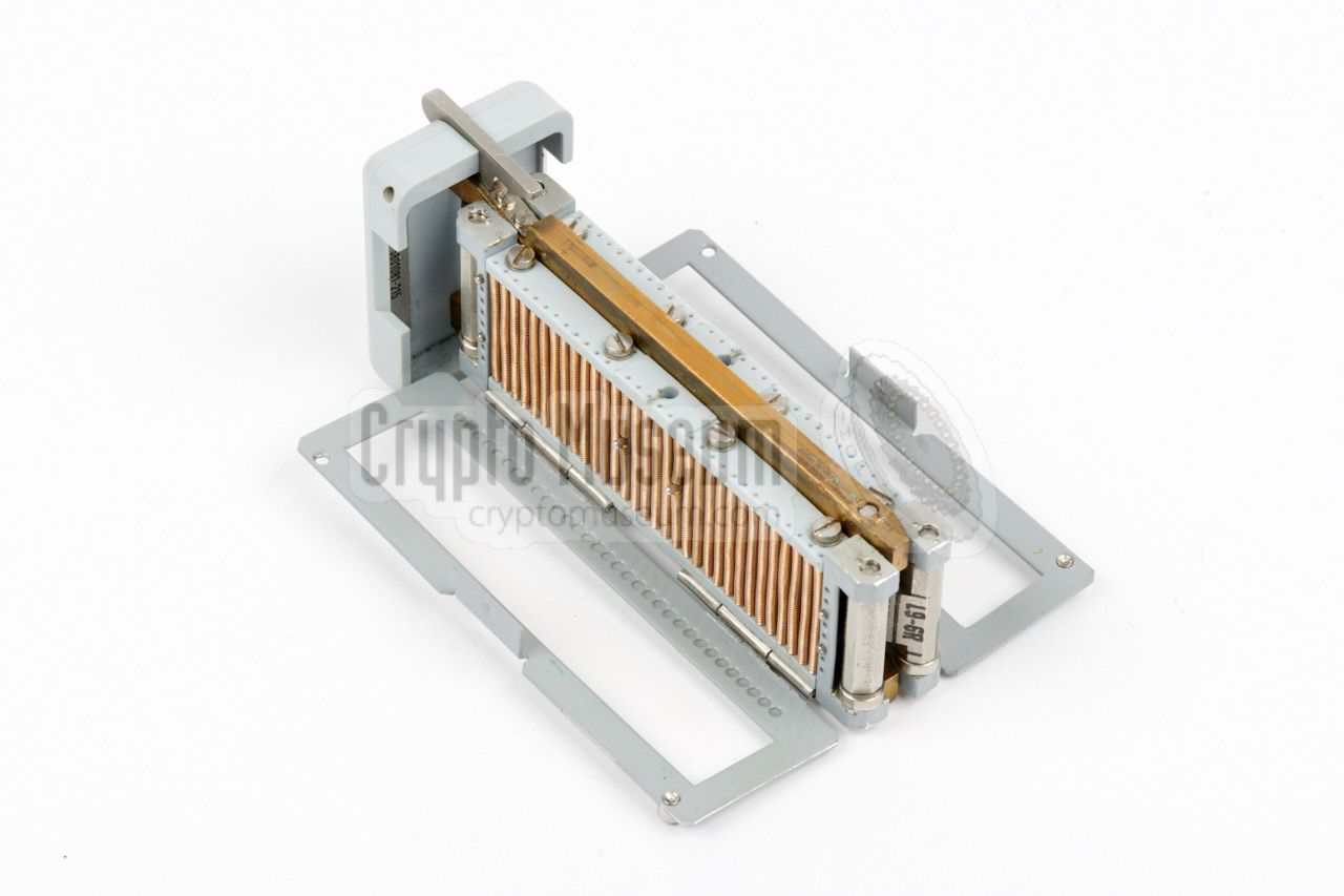
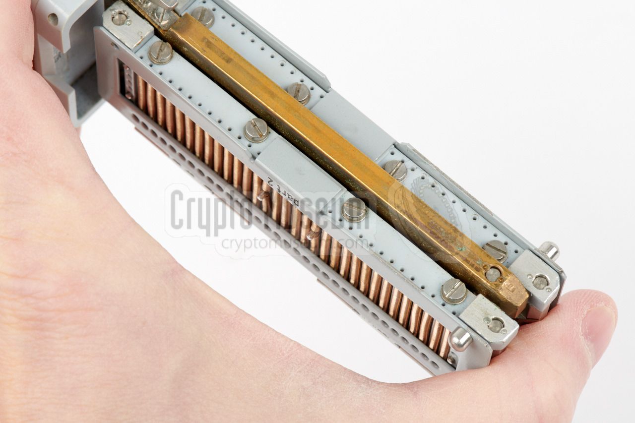
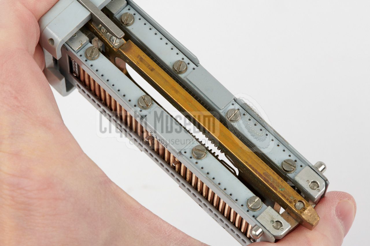
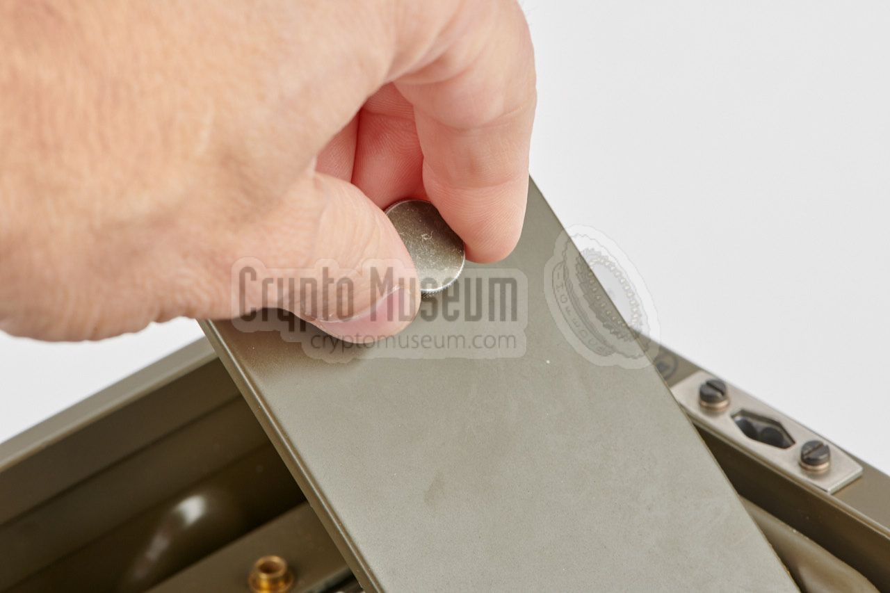
The two pieces of punched paper tape are first installed in the so-called
key block, which is a spring-loaded metal bracket in which one tape
is installed at either side. It is held in place by a hinged metal frame.
At the center of the key block are
32 copper-plated springs that are all
connected to the electric ground. Two
metal pins at the center are for
aligning the punched tape.
As the key block accepts 5-level paper tape and has 32 spring positions,
it is likely that each side of the key block specifies 32 5-bit characters,
which implies a possible key length of 320 bits.
|
|
|
|
The image above shows the rectangular key block with both hinged frames open,
ready to accept two key tapes. The frames are marked part 1 and part 2
respectively, corresponding to the two paper tapes. The key block measures
approx. 110 x 38 x 21 mm (without the cap at the front).
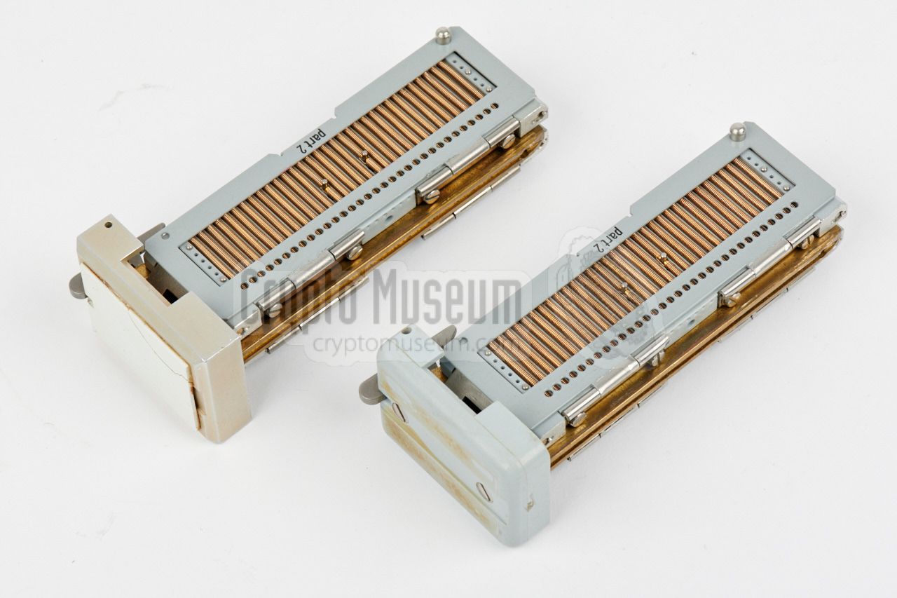
The Elcrovox 1/3 was usually supplied with a minimum of
two key blocks,
so that one could be prepaired for the next key, whilst the other one
was in use. At midnight the blocks were swapped.
|
|
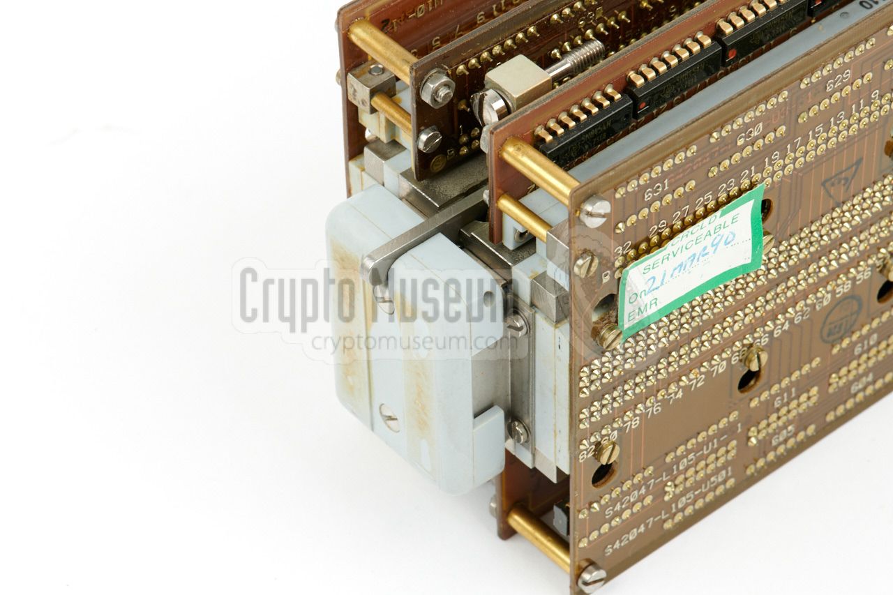
The presence and absence of holes in the key tape, represent the individual
bits of the key, that are stored in the latching circuit on the four printed
circuit boards that surround the tape reader. The key bits are then used
as the seed or initialisation vector of the internal (probably
non-linear) pseudo random number generator (PRNG), that generates a
key stream with a, extremely long cipher period.
The latter means that it takes a long time before the key sequence repeates itself.
|
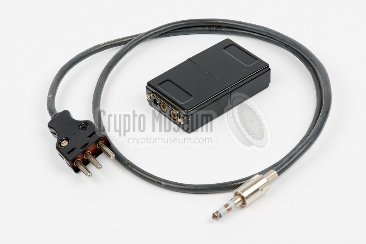
Several test devices were available for testing the performance of the
Elcrovox 1/3 and for finding faults in its operation. The image on the
right shows Test Device 1 (German: Prüfgerät 1), that can be connected
directly to the Elcrovox 1/3.
The device consists of a small junction box with a standard 10-pin NATO
headset, plus a short cable with a 19-pin and an a 41-pin plug at the end.
Furthermore, a 10-pin loop connector is attached with a chain to the 41-pin
plug.
|
|
|
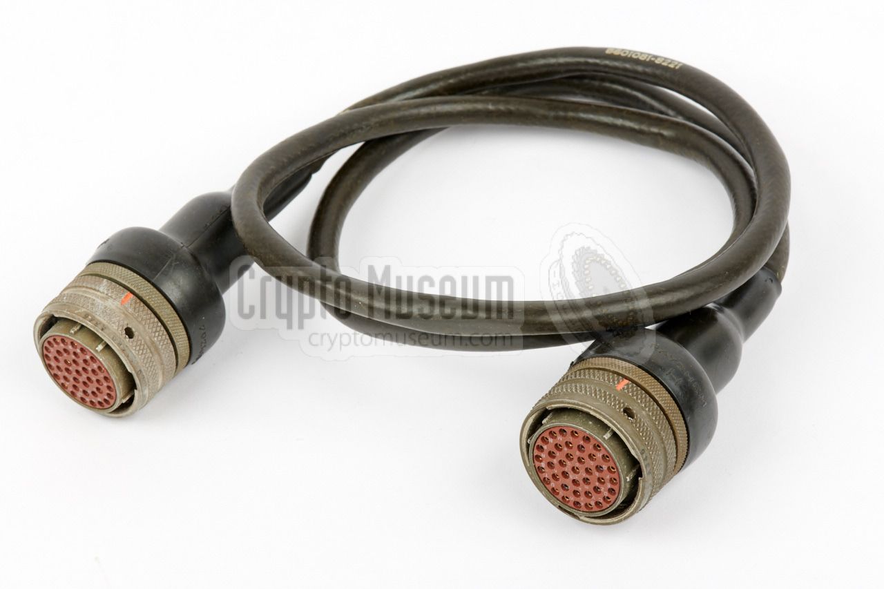
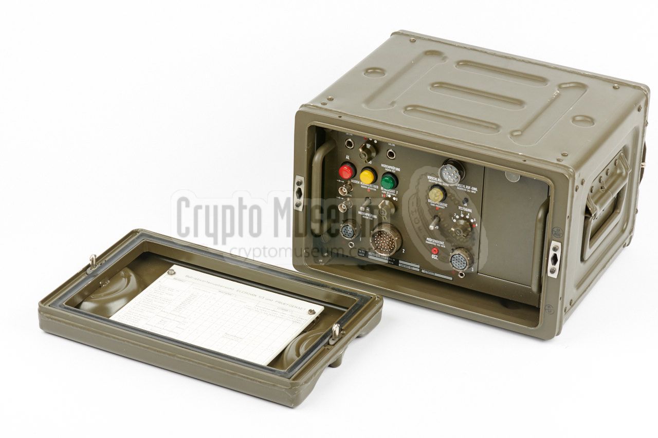
The image on the right shows Test Device 2 (German: Prüfgerät 2),
that can be connected directly to the Elcrovox 1/3 via three 1 metre
long patch cables.
The device was used for testing the performance of the
Elcrovox 1/3 and for finding faults in its operation.
The device comes with four test cards that are stored behind the hinged
door at the right. These cards are intended to replace specific cards inside
the Elcrovox 1/3 during the test.
|
|
|
Especially for testing the functionaly of the Elcrovox 1/3
and for discovering faults in its crypto functions, a series of
test tapes were issued. The image on the right shows a set of test keys
tapes for the Elcrotel 4 cipher machine, that are also suitable for the
Elcrovox 1/3.
The set consists of three bundles of short red and blue test tapes,
marked TEST 01 (a real key), TEST 02 (all holes) and TEST 03 (no holes).
The yellow tapes are not used on the Elcrovox 1/3.
|
|
|
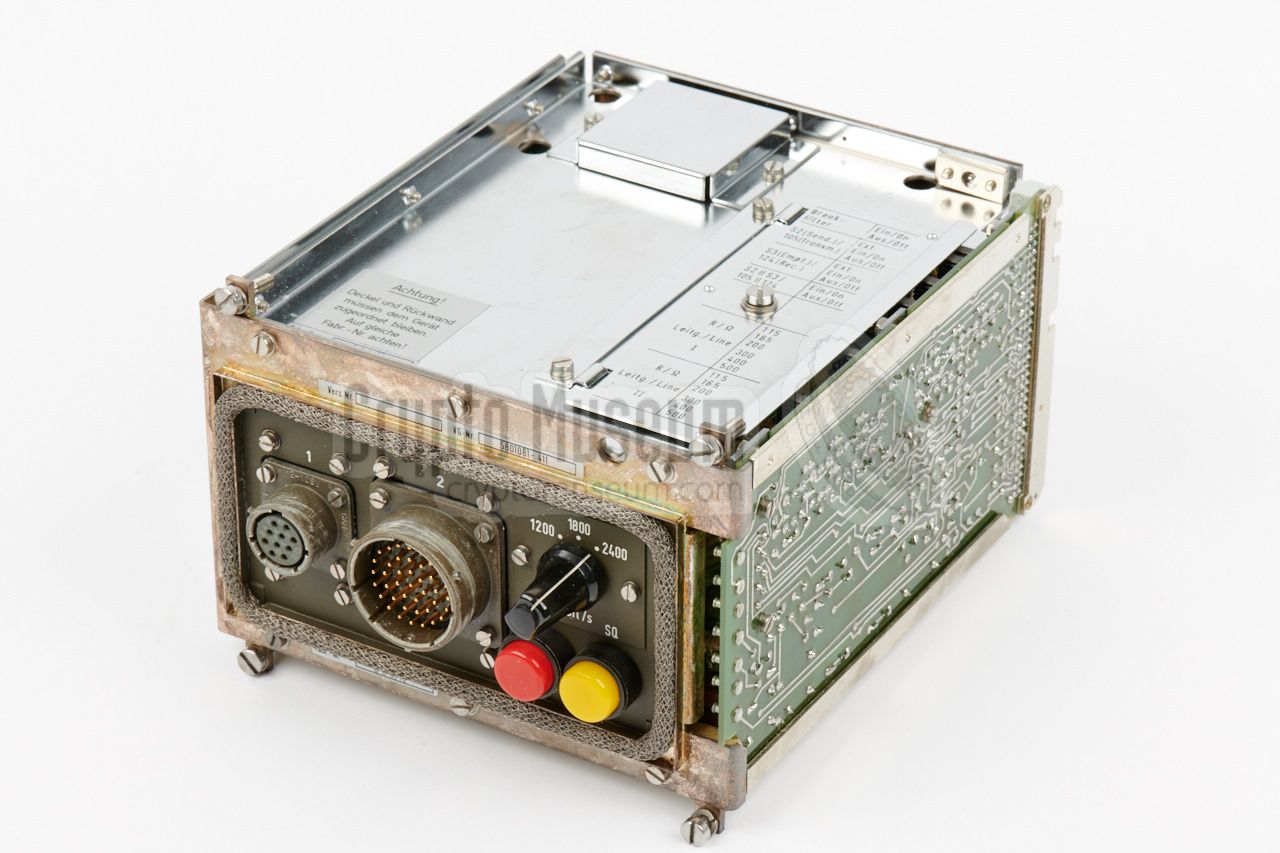
In order to allow quick and efficient repair of an Elcrovox 1/3
unit in the field, a collection of spare parts was
supplied to countries that used the device. The spare parts were usually
supplied in a large aluminium transport case.
With the exception of the actual cipher unit (also known as the crypto logic),
a broken device could be repaired within minutes, simply by swapping the
defective module. Repairs to the crypto logic were only carried out by
Siemens.
|
|
|
At present, no further information about the Elcrovox 1/3 is available.
You can help expand this page by providing additional information and
material. For contributions, please contact us.
|
- Museumsiftung Post und Telekommunikation, Image of Elcrovox 1/3
Frankfurt (Germany). Retrieved September 2017.
- Anonymous, Prüfgerät 2 für Elcrovox 1/3 - THANKS !
Elcrovox 1/3 Test Device 2. September 2017.
- The Joint Chiefs of Staff, Memorandum for Record
WINTEX 83 First Impressions Conference, 22 March 1983.
Declassified 14 December 2012, EO 13526.
|
|
|
|
Any links shown in red are currently unavailable.
If you like the information on this website, why not make a donation?
© Crypto Museum. Created: Thursday 21 September 2017. Last changed: Wednesday, 24 August 2022 - 20:21 CET.
|
 |

|
|
|


![Elcrovox 1/3. Photograph courtesy Museumstiftung Post und Telekommunikation [1].](img/evx13_large.jpg)


