|
|
|
|
|

|
Key generator
PU-104 was a key generator for
perforated paper tape, made around 1986
by Rohde & Schwarz (R&S) in München (Munich, Germany).
The device was able to create long sequences of truly random numbers
and send them to external paper tape puncher via its built-in
V.24 interface.
|
The device is housed in a grey-and-blue Rohde & Schwarz enclosure that is
typical for the era. It measures 34 x 21 x 14 cm and weighs 6.3 kg.
At the front
is a DB25/F socket (V.24/RS232) for connection of an external tape puncher.
A rotary selector allows the number
of copies (tapes) to be set between 1 and 9. Furthermore there are
two buttons, marked NEW KEY and KEY OUTPUT, each with a corresponding red LED.
The current status of the device is reported via a single digit 7-segment
LED display. When in use, the display counts down the number of copies to
be created.
|
|
|
The device has built-in test equipment (BITE), which means that its functions
are tested on startup, but also continuously during its operation.
Any errors are reported on the display. At
the rear is a EURO-socket for
connection to the AC mains, plus a 3-pin XLR/M socket for connection
of two external batteries. On some versions of the PU-104,
these batteries were placed internally.
It is currently unknown in what year the PU-104 was developed and when it
was released, if it was released at all. Most of the components inside the
device have manufacturing codes of 1983 and 1984, which suggests that development
took place around that time. Two of the RAM chips have a date code of 1985
and one EPROM was issued on 28 October 1986, which indicates that it was
probably released in 1986.
If you have any further information about this device,
let us know.
|
Although we do not have access to the original documentation or
circuit diagrams of the PU-104, we can make a few educated guesses
about its operation, simply by studying the interior. Below
is a block diagram that explains the global operation of the device.
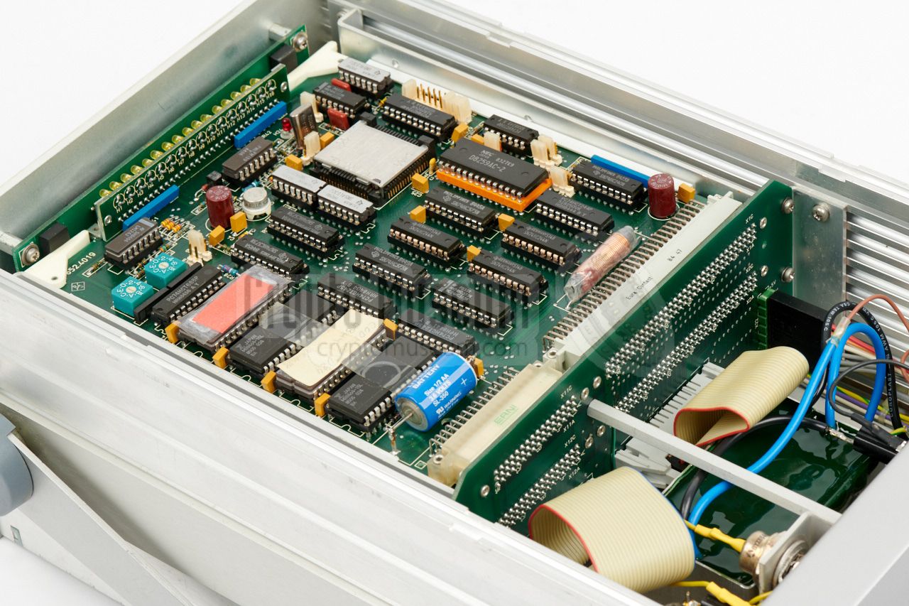
At the bottom left is a true random number generator, in which a
diode is used as the source of evenly spread 'white' noise.
At the bottom right is the V.24 (RS232) output to the tape puncher.
All parts are under control of a central processing unit (CPU) that
has its own RAM and EPROM memory. It controls all functions of the
device and validates the generated random numbers,
raising an alarm when it fails.
|
|
The PU-104 consists of a strong metal frame with a heavy adjustable grip,
and two blue case shells – one
at the top and one at the bottom – hiding the interior.
The interior can be accessed by loosening 4 bolts at either
side of the device, after which the blue case shells can be removed.
|
Front and back panel are affixed to the extruded aluminium frame.
The image on the right shows the interior of the PU-104/C1 after removing
the two case shells and dismounting the front panel.
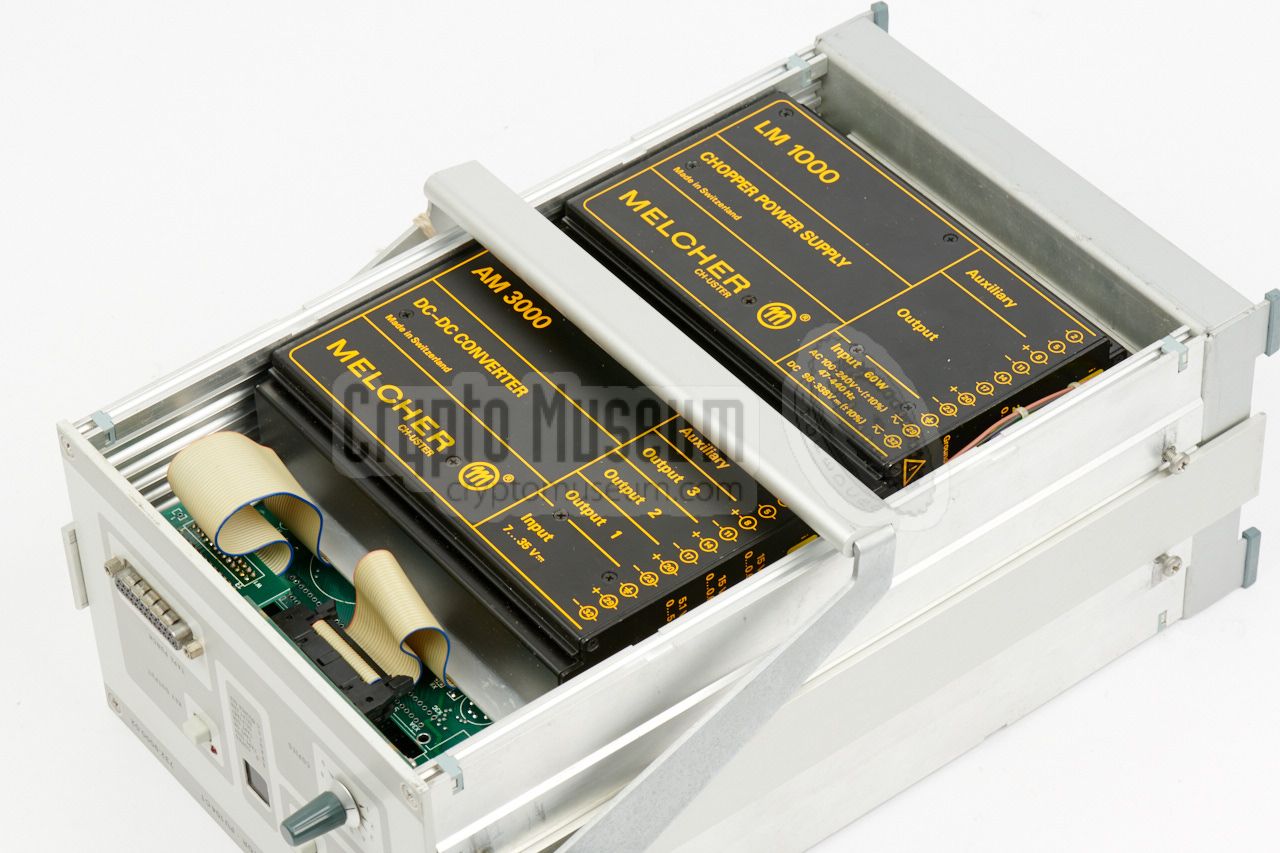
At the rear is a large mains filter
that separates the PSU from the mains.
The actual PSU consists of two large pre-fabricated MELCHER modules
– a switched mode power supply (SMPS) and a DC-DC converter –
that are located at the bottom.
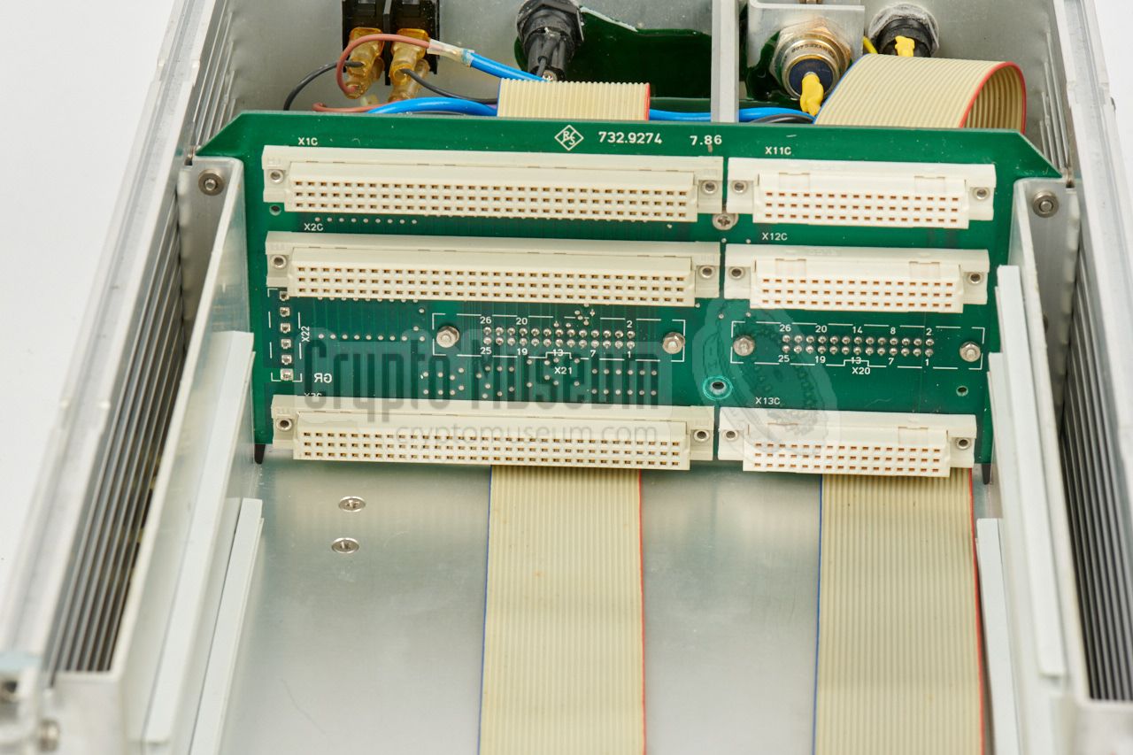
About 1/3rd from the rear is a vertical backplane
into which three large PCBs are slotted.
The front panel
is connected to it via two ribbon cables.
|
|
|
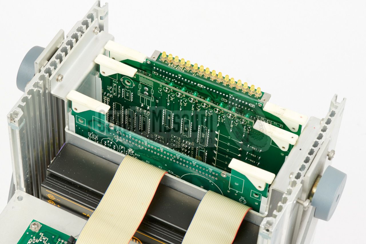
At the front edge of the processor board is a vertical PCB with 16 yellow
LEDs that probably show the status of the processor's data lines.
These LEDs are normally not visible to the user.
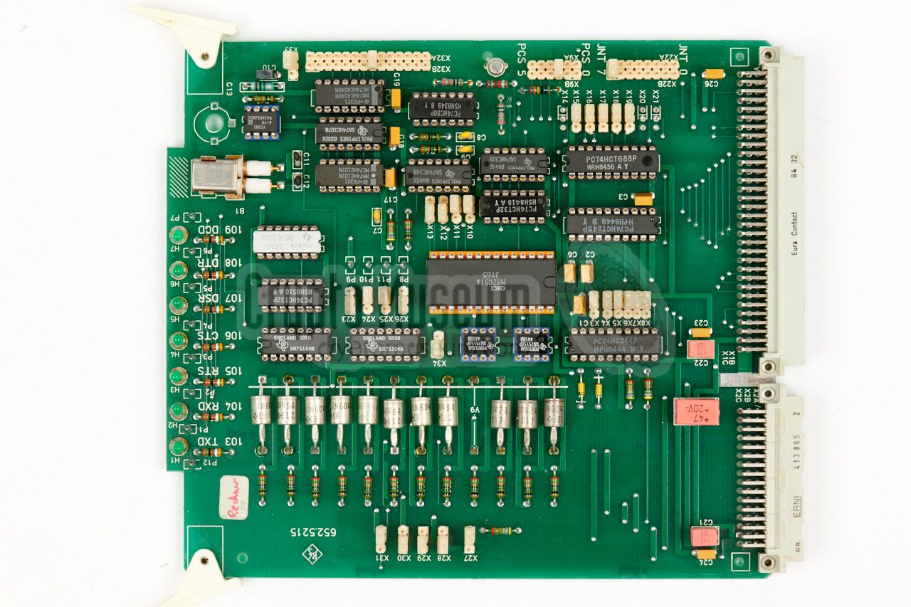
The middle board
contains the V.24 or RS232 interface, which is built around an OKI
M82C51 Universal Synchronous Asynchronous Receiver Transmitter (USART).
At the front edge of this PCD are 7 green LEDs that show the status of
the RS232 lines. These LEDs are invisible to the user.
The row of big diodes that is present on this board, was probably for protection
of the lines.
|
|
|
|
V.24/RS232 interfaces were fairly common in the 1980s and 90s for the connection
of peripheral equipment like printers and modems. On PCs they are commonly known
as COM-ports.
The bottom of the V.24 board is heavily patched,
indicating that this might be an early a prototype.
|
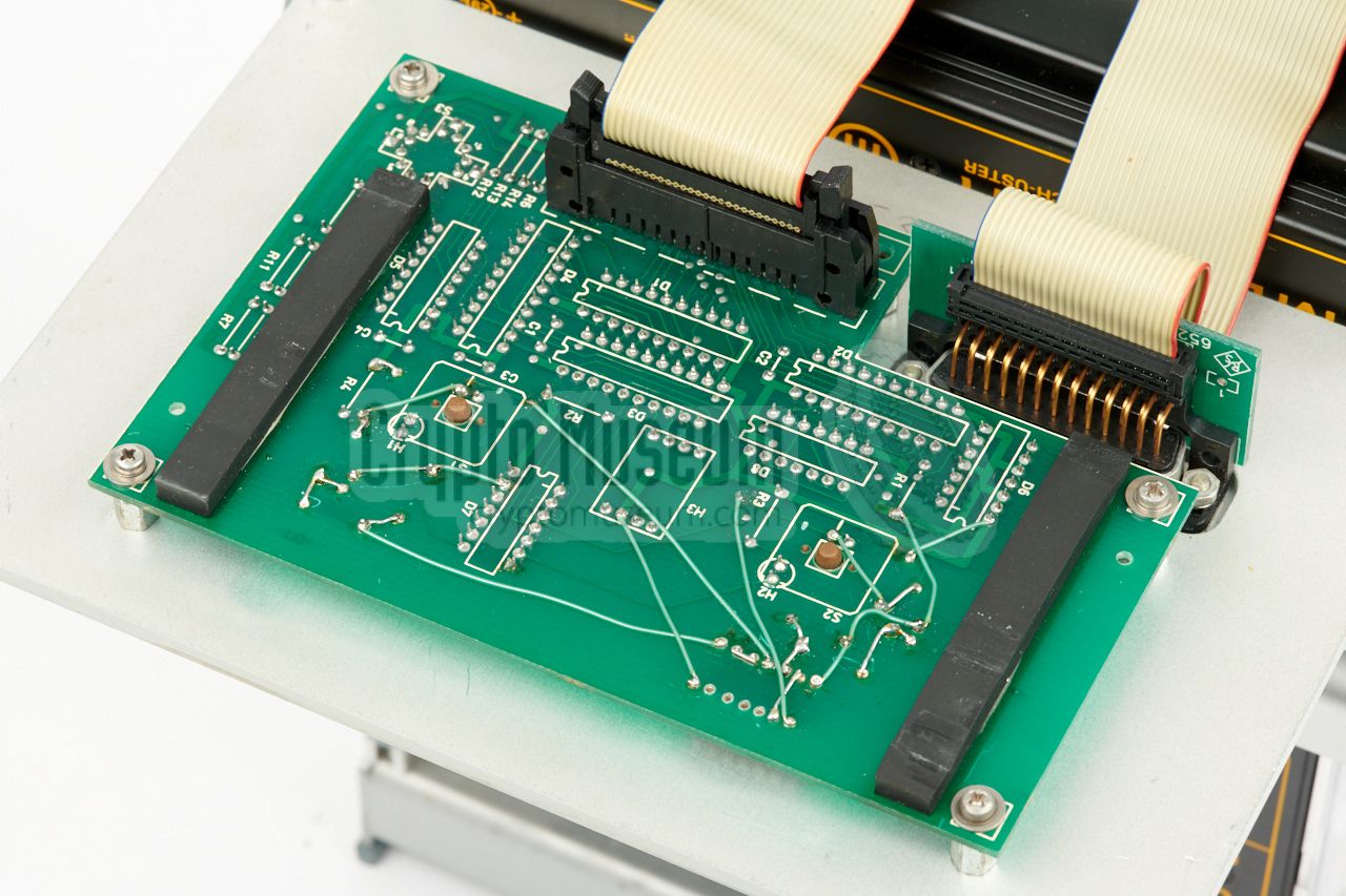
The bottom board
is likely the most interesting one, as it contains
a Random Number Generator (RNG). It is built around a noise diode with two
PM156 Operational Amplifiers (OpAmps),
that drive a JK flip-flop and several
ripple counters.
Also on this board is a 1 MHz/4MHz oscillator.
The board contains additional logic for checking the randomness of the
generated noise. This is done by counting the occurency of each word-value
and comparing it with a preset tolerance window,
generating an SOURCE DEF alarm on the front panel display if it has become biassed.
|
|
|
|
The RNG occupies about half the space on this board. The other half
is reserved for two batteries and three large capacitors (super-caps)
that have not been assembled on the board shown here.
Judging from the large number of patches and modifications and the absence
of a serial number plate, the PU-104 shown here is probably an early
development prototype or engineering sample.
|
-
RAM = Random Access Memory.
-
EPROM = Erasable Programmable Read Only Memory.
|
At present, we have no further information about the PU-104, except for
the Operating and Service Manual of the V.24 card (PU 104 S2), which
is available for download below.
If you know what the device was used for and by which organisation(s),
or if you have any further information or documentation – like a user
manual, a service manual or any brochures – please contact us.
|
- Handbuch 2 x V.24 Interface, PU 104 S2 1
652.3812 - Handbook and Service Manual (German).
Rohde & Schwarz. April 1986—April 1987.
- 80186, High-integration 16-bit microprocessor
Intel 1982-1995.
- MB8464A Static Random Access Memory with Data Retention Mode, datasheet
Fujutsu Microelectronics, 1978.
- D8259 Programmable Interrupt Controller, datasheet
Digital Core Design, 1999-2007.
- MSM82C51 USART, datasheet
OKI, January 1998.
- PM156, Monolothic JFET-Input Operational Amplifier, datasheet
Analog Devices, date unknown.
|
-
Manual kindly provided by Helmut Singer [2].
|
- Anonymous, PU-104 C1
Information received June 2014.
- Helmut Singer, PU 104 S2 manual - THANKS !
Received April 2018.
|
|
|
|
Any links shown in red are currently unavailable.
If you like the information on this website, why not make a donation?
© Crypto Museum. Created: Monday 26 March 2018. Last changed: Wednesday, 05 November 2025 - 11:53 CET.
|
 |

|
|
|