|
|
|
|
|

|
|
← Racal Voice
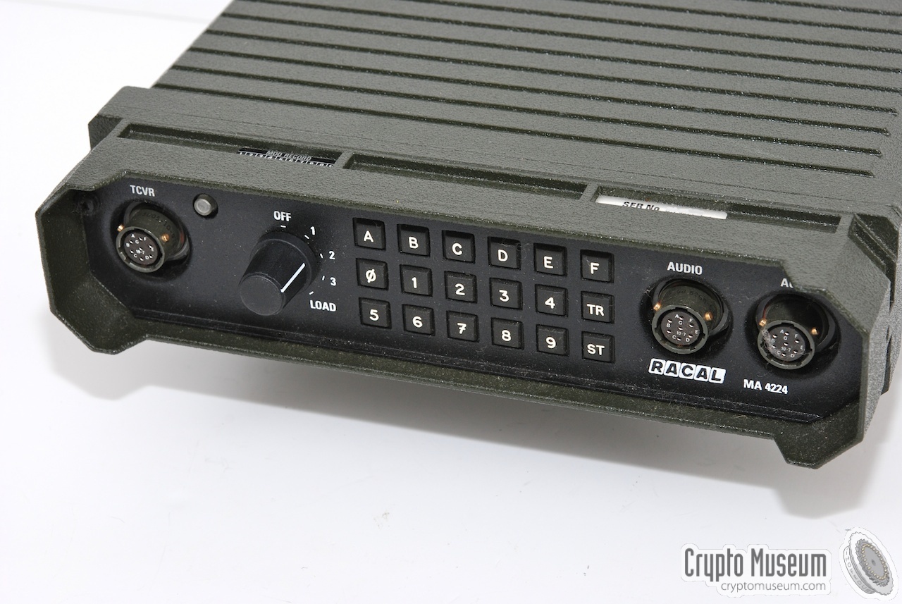
The image on the right shows a typical MA-4224 unit.
It can accomodate up to 3 Traffic Encryption Keys (TEK) that are selected
with a rotary switch at the front panel. Keys are entered by means of a fill
gun or directly on the keyboard. The latter can be cumbersome as the unit
doesn't have a display to verify the input.
The MA-4224 can also be used as a phone encryption unit. For that purpose it
would be fitted in a standard briefcase, together with an acoustic coupler and
a power supply unit (PSU). A hinge allowed the front panel to be tilted.
|
|
|
As becomes clear from the description below, the MA-4224 is built from
conventional (discrete) components, spread over 3 rather large PCBs.
The MA-4224 was eventually replaced by the much smaller
MA-4225, which is effectively a miniaturized version
of the MA-4224.
|
|
Looking inside the MA-4224 reveals a rather nice piece of conventional
electronics. From the manufacturing codes on the chips it appears that
the unit was designed in the late 1980s and manufactured in 1990.
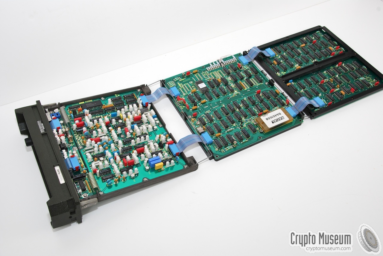
The interior consists of three PCBs that are nicely stacked together.
|
The three board are connected by means of a series of blue-ribbon
flatcables.
The image on the right shows the digital board that is at the bottom
of the PCB stack. Surprisingly, it doesn't contain a microprocessor,
which means it is completely driven by discrete CMOS logic.
At the top right of the board is a molded backup battery, that is used
to retain the cryptographic keys that are stored in the static memory
chip on one of the other boards.
At the other side is the analog board
that contains the RAM chip and in the middle is the
logic board.
|
|
|
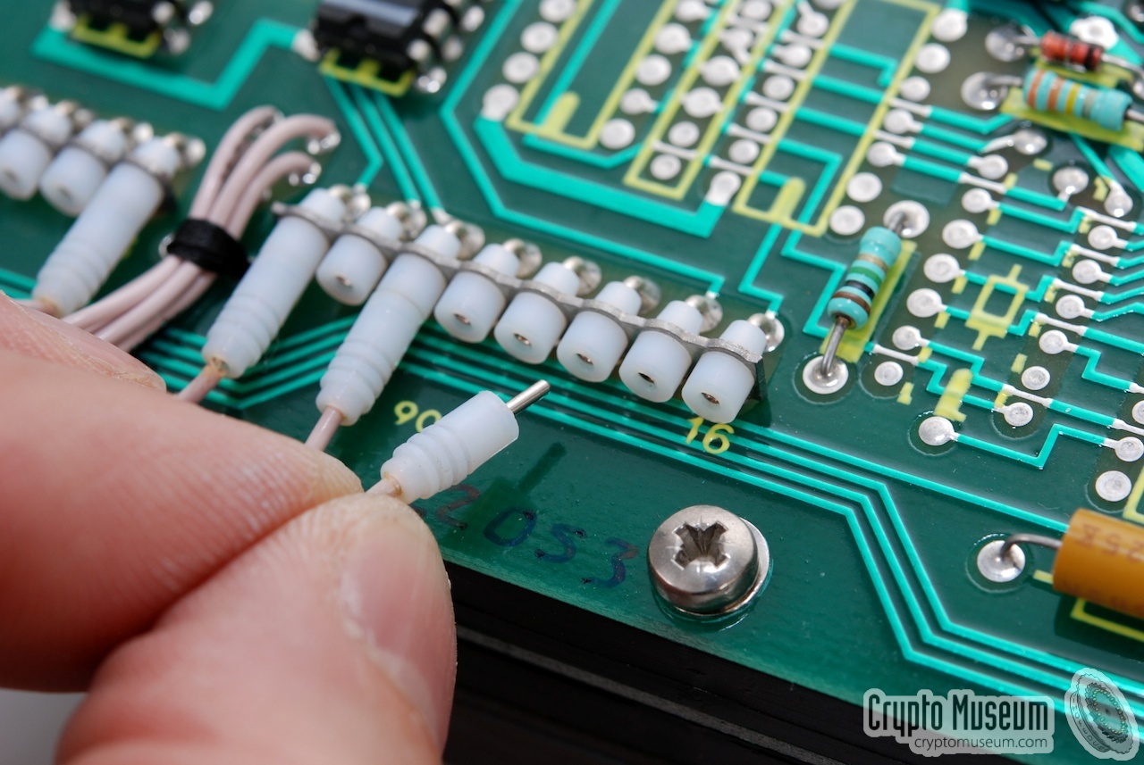
At the left side of the digital board is a row of
small sockets with
tiny little plugs that can be used to
change the configuration of the
unit. At present the effect of the plugs in unknown.
|
The MA-4224 is very service-friendly. By removing the right screws from
the PCBs, the complete unit can be unfolded. The PCB are held together
by two clever hinges, as can be seen in the image on the right.
The rightmost board in the picture is the logic board that is normally
folded in between the other two boards.
When unfolded like this, the front panel can be re-attached and the unit
can be operated normally. All components are on the upper side of the boards.
After all these years one terminal of the battery (on the digital board) is
corroded.
|
|
|
|
|
|
Any links shown in red are currently unavailable.
If you like the information on this website, why not make a donation?
© Crypto Museum. Created: Thursday 26 August 2010. Last changed: Monday, 02 March 2020 - 20:16 CET.
|
 |

|
|
|