|
|
|
|
|

|
|
← Racal Voice
Time-division voice scrambler
The MA-4204 is a low-grade military voice encryption unit, designed and built
in the early 1970s by Racal Datacom Ltd in the UK.
The device uses a time-division scrambling
technique which shuffles small
time segments in a pseudo-random sequence that changes every half second.
It is suitable for narrow-band voice transmission on HF and VHF bands, in tactical
(military) situations.
|
The scrambling order of the time segments changes each half second
and is controlled by a pseudo-random number generator (PRNG).
The PRNG itself can be controlled by three rotary switches at the top half of
the front panel.
Each switch has 8 positions, creating 512 possible sequences (8 x 8 x 8).
Although 512 combinations provides hardly any protection, it was considered
sufficient for tactical use at the time. With modern techniques it should be
relatively easy to break the code, simply by observing the discontinuities
in the signal.
|
|
|
The MA-4204 can be used for voice signals in any mode (AM, FM, SSB) but
also for keyed signals (morse, CW).
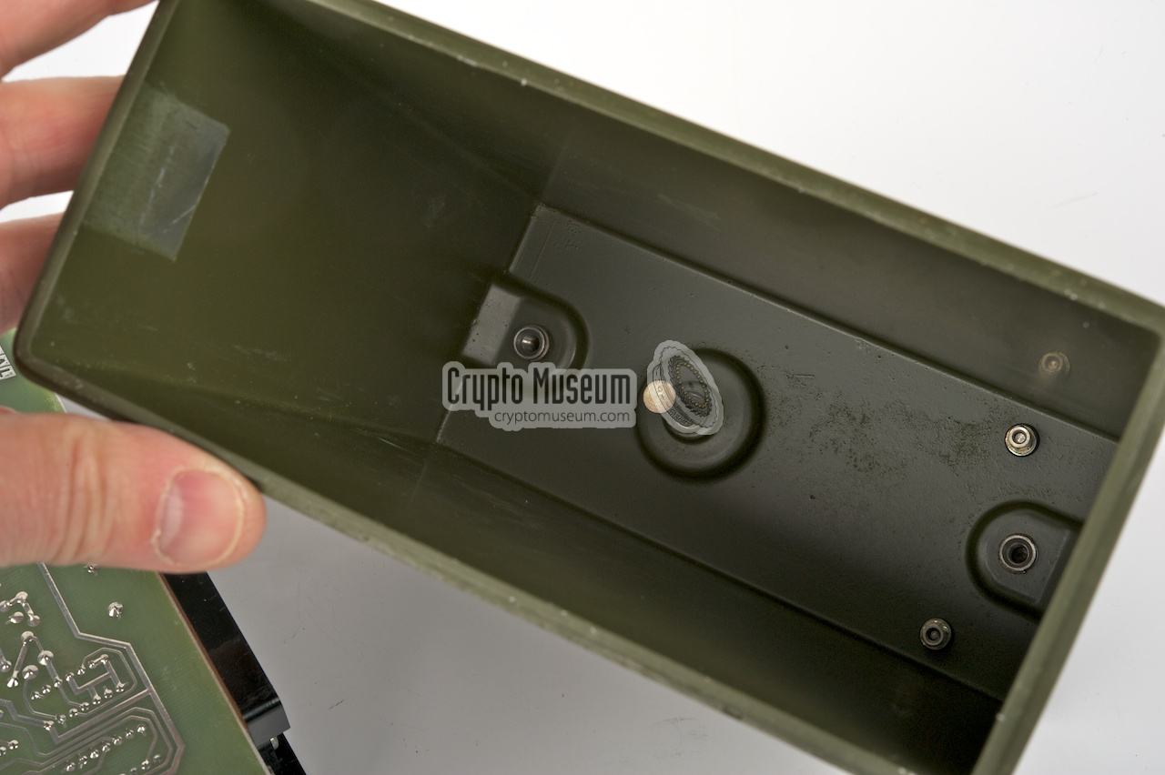
The MA-4204 can be powered directly from the transceiver (TCVR) or from
an optional battery that can be attached to the bottom
of the device.
The MA-4204 belongs to the same family of devices as the slightly more
advanced MA-4014B,
that has 5 code-selectors.
|
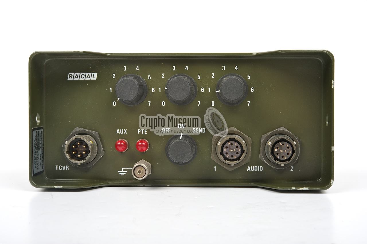
The MA-4204 is extremely easy to operate and has very few controls and
indicators. It is connected to a radio set and suitable accessories through
the 3 connectors at the front panel. Once connected, the mode of
operation can be selected with the 3-position rotary switch at the bottom
center (MODE). The required scrambling code is selected with the 3
switches at the top.
Two red indicators are present to the right of the TCVR connector,
marked AUX and PTE. The AUX indicator lights up when the unit gets
power from the connected transceiver (see below).
The PTE indicator lights up in PRIVATE or ENCRYPTED mode.
It flashes when the voltage drops too low.
|
- OFF
This mode bypasses the encryption and decryption circuits of the MA-4204.
It forces communication in CLEAR.
- ON
In this mode, automatic encryption is enabled. It can be used for the
reception of CLEAR signals, whilst it switches automatically to decryption
when a suitable synchronising signal is detected.
- SEND
This mode forces continuous transmission in encrypted mode.
|
The MA-4204 has three connectors at the front, through which all signals
and power lines are connected. The leftmost connector (TCVR) is intended
for connection to a transceiver. It is also used to supply power to the
unit. The unit can be fed by any DC power source between 12 and 30V
and draws just 120mA.
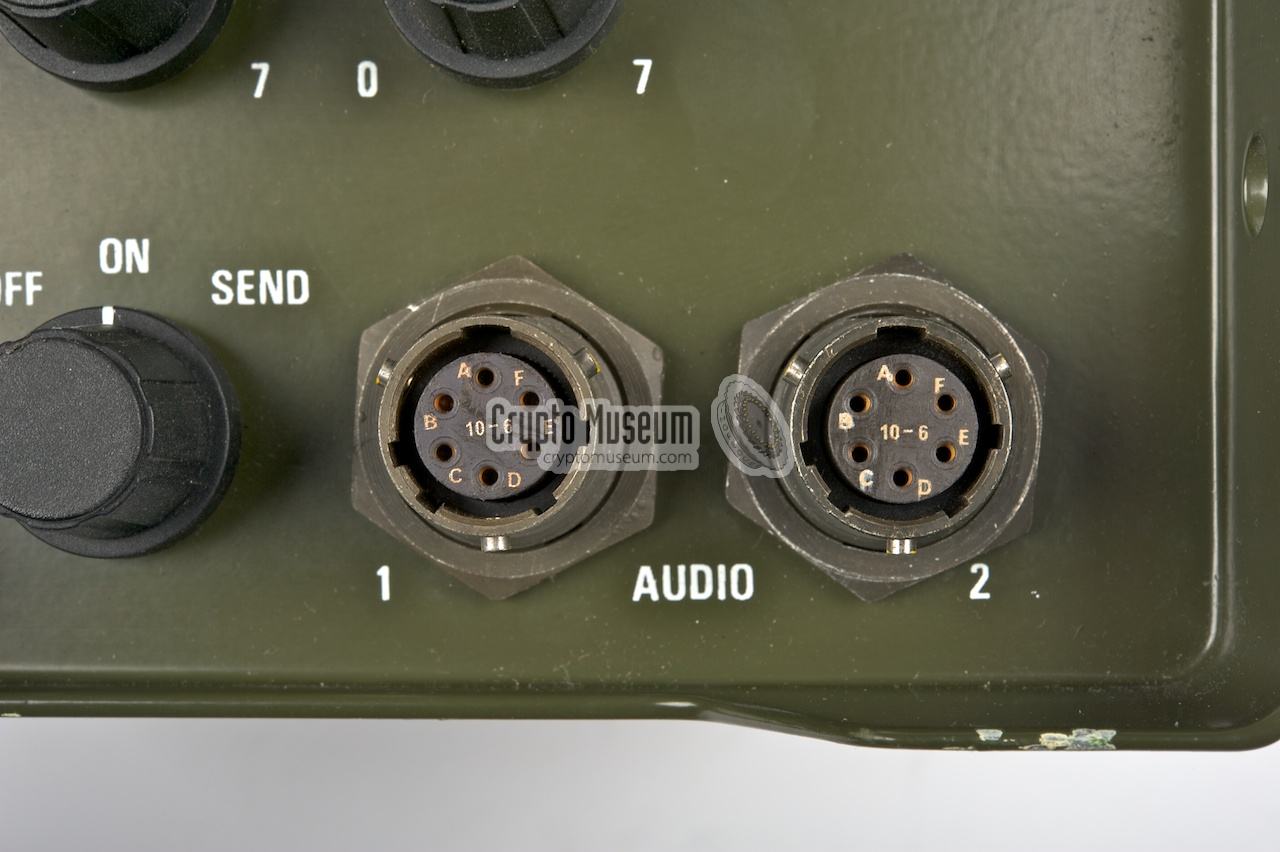
Socket AUDIO 1 is used for the connection of a handset, a morse KEY or
a battery charger (when the external battery MA-968A is used).
AUDIO 2 can be used for connecting an extra handset or ancillary equipment.
TCVR (Transceiver)
|
- MIC out (to transceiver)
- Power (+12 to 30V)
- PTT out (to transceiver)
- GND (common rail)
- KEY out (when MODE-switch is OFF)
- Audio in (from transceiver)
|
|
- MIC in
- Battery supply
- PTT in
- GND (common rail)
- Key
- AUDIO out
|
|
- MIC in
- AUX supply output
- PTT in
- GND (common rail)
- PRIVATE indicator (remote)
- AUDIO out
|
|
Inside the MA-4014B, speech is first digitized using a Delta-Sigma modulator,
which produces a data stream with a bit-rate of 32 kbps (kilo-bits per second).
The data is temporarily stored in memory, where it is divided into eight
segments of 2048 bits each (2 kb). This way, each segment represents 62.5 ms,
with 500 ms for all 8 segments. The eight segments are then scrambled.
Scrambling of the eight segment is controlled by a pseudo random generator,
assisted by pre-recorded scrambling orders that were stored in ROM. These
pre-recorded orders were carefully selected to guarantee minimum
intelligibility. After scrambling, the data was coverted back to an
analogue signal again, so that it could be transmitted over a standard
voice channel.
|
|
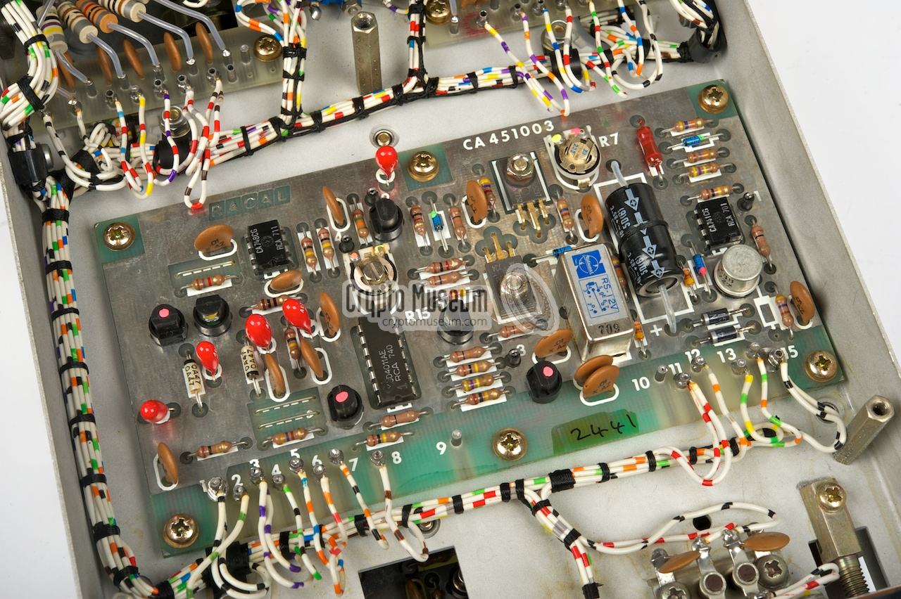
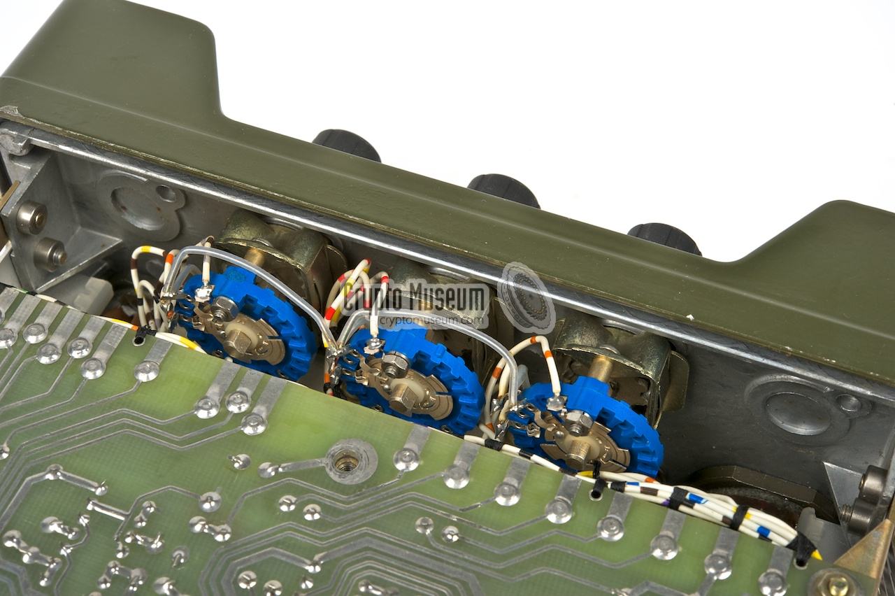
The interior of the MA-4204 can be accessed easily by
removing two large bolts
from the bottom and pulling the front panel
out of the case.
The interior consists of a metal frame with 4 PCBs. The outmost PCBs
(top and bottom) can be released and
'folded away' as shown below.
|
In the past few years (2010), the surplus market has been flooded with
MA-4204 units. Although they hardly provide any protection these days,
they can be demonstrated as part of a hobbyist project.
The information provided on this page should be sufficient to connect
the unit to a rig.
|
At present, we have no access to the user manual or the service manual of
the MA-4204. Much of the characteristics of this device have been deduced
from the manual of the slightly more advanced MA-4014B. If you have access to
any of these manuals, or if you have further information about these devices,
please contact us.
|
- Racal Datacom Ltd., Technical Manual, MA. 4014B, Audio Encryption Unit
Ref. WOH 5062. Issue 1.1.75-150.
- Signetics, 2524 and 2525 datasheet
512 and 1024 bit Recirculating Dynamic Shift Registers.
Publication date unknown. Retrieved April 2012.
|
|
|
|
Any links shown in red are currently unavailable.
If you like the information on this website, why not make a donation?
© Crypto Museum. Created: Monday 02 August 2010. Last changed: Saturday, 24 February 2018 - 16:34 CET.
|
 |

|
|
|