|
|
|
|
|

|
|
FILL DS-102 Philips UP-2101 →
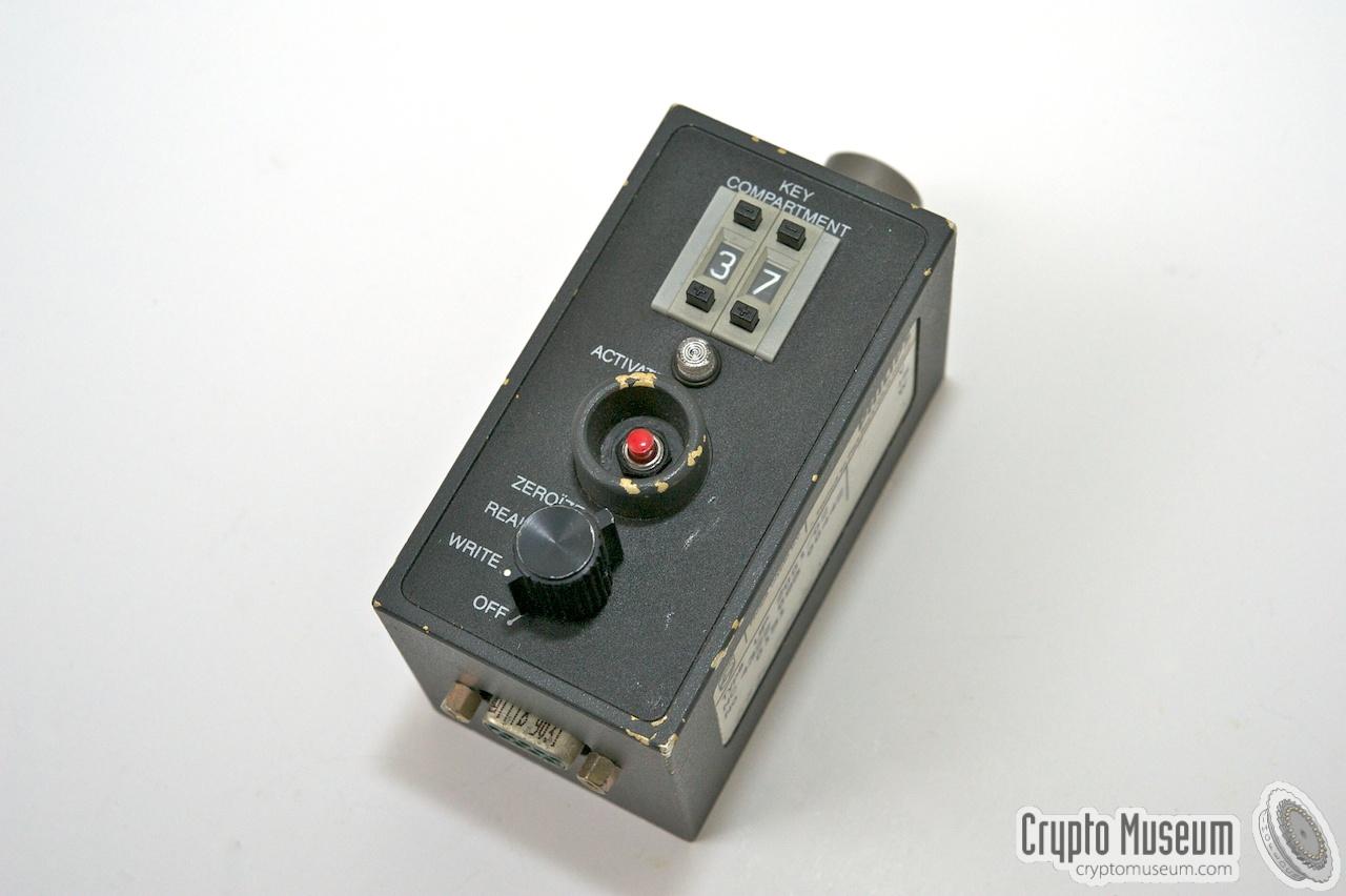
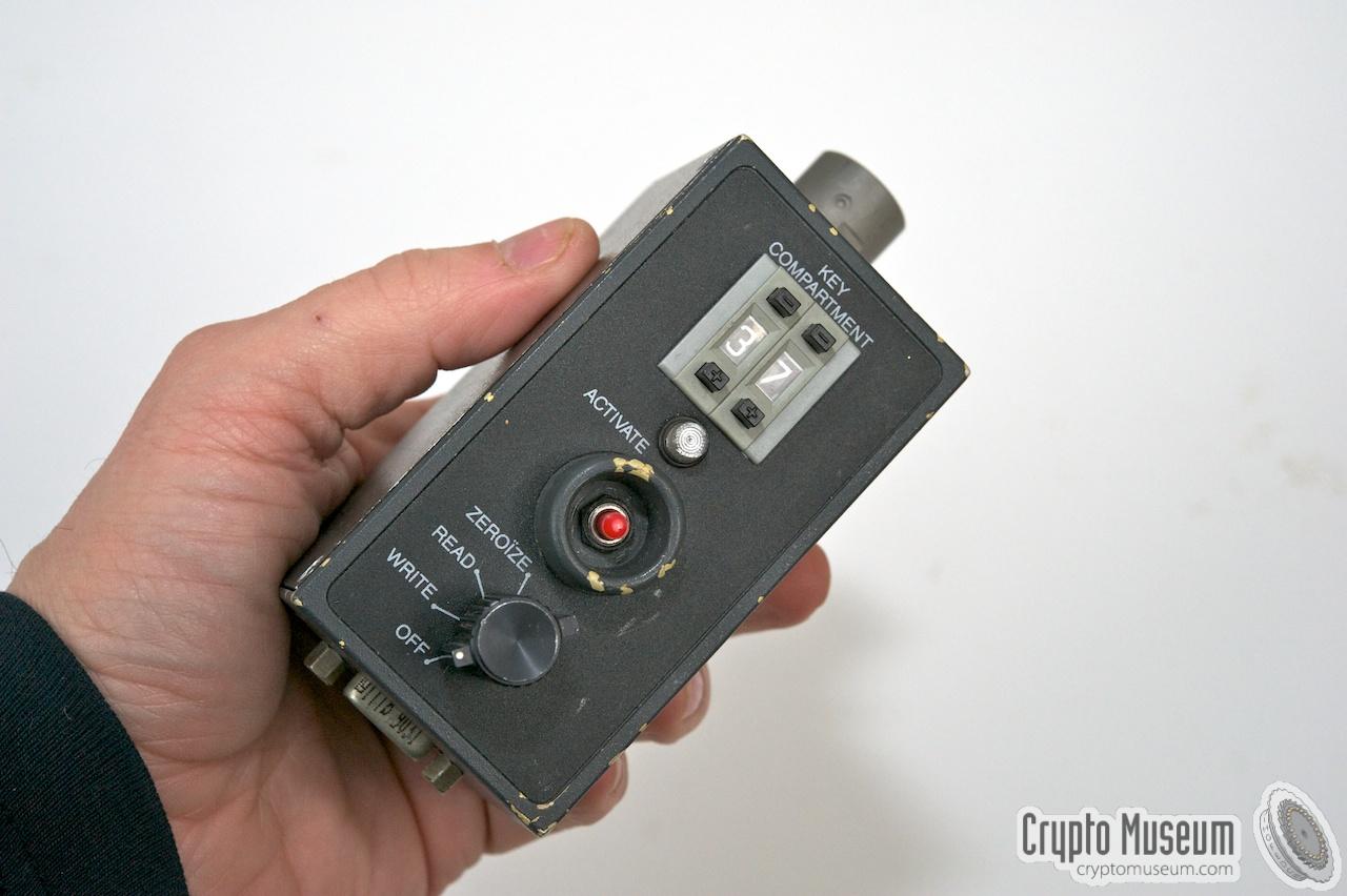
It has a rotary switch that is used to select the mode of operation.
At the center is a recessed ACTIVATE button that is used in combination with
a particular setting of the mode selector.
The mode selector is also used for loading keys via the DE9 connector at
the bottom and writing them out to the
U-229 connector at the top.
The image on the right shows a typical UP-2001,
as it was found on a Dutch fleamarket in 2011 [1].
It is similar in appearance to the American KYK-13
but is slightly bigger and uses a 5-pin U-229 connector,
rather than the 6-pin U-329.
|
|
|
The UP-2001 has some important improvements over the
KYK-13. First of all
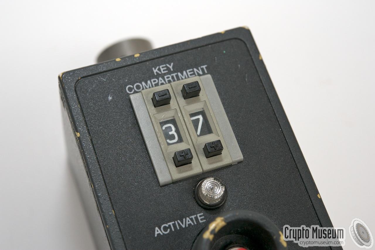
is has room for 40 sets of key variables, commonly referred to as
compartments, whereas the KYK-13 has just six.
A key compartment is selected by setting the 2-digit selector
at the top to the required number (00-39).
This greatly increases the number of keys
that can be carried around simultaneously.
The device has a common U-229 fill connector,
for direct connection to encryption equipment like the
Spendex 40,
Spendex 50
and BVO.
It also has a standard RS-232 serial port in the form of a DB-9 socket at the bottom,
allowing keys to be loaded directly from a Personal Computer (PC) or
a special HP barcode reader.
The UP-2001 was succeeded in 1992 by the UP-2101.
|
THANKS —
The UP-2001 featured on this page was donated to Crypto Museum in 2012 by
mr. Remco Hopman [1]. He had found the device for a very modest price on a local
fleamarket in 2011. It had probably been used with a
Spendex 40 crypto phone, as the text
'fill gun (spendex)' is
pencil-written on its side.
Keys can be loaded into the UP-2001 by means of a (DOS) PC running the
UP-2002 Net Key Program (NKP) software
[2].
For this, the DE9 connector of the UP-2001 was connected to the COM1 port
of the PC via a simple 2-wire cable. Keys were generated by the NKP
and were then transferred to the UP-2001 via the serial port, one at a time,
each with a suitable checksum.
This was done by placing the MODE selector on the UP-2001 in the
WRITE position and selecting the desired key compartment (00-39).
Next, the Net Key Program on the PC (UP-2002) is instructed to
send the key (with the calculated checksum) to its COM port.
The UP-2001 will produce one long beep when a valid key has been read,
or three short beeps when it is wrong.
|
|
It was also possible to load keys into the UP-2001 via barcodes,
by using an HP HBCR-8300 barcode
reader [4].
The UP-2002 NKP (see above) could be used
to print suitable barcodes onto paper. This allowed the keys to be sent
securely by means of a (trusted) courier, or via a fax unit connected to
a secure crypto telephone – such as the Spendex 40 –
or the PFDX fax encryptor .
|
The image on the right shows a typical Hewlett-Packard HBCR-8300
stylus-type barcode reader as it was used at Philips with the UP-2001.
It is connected to the UP-2001 by means of the 9-pin male DE9 connector
at the end of the cable.
Although the interface of this barcode reader is specified as RS232,
its signal levels are at TTL level (0-5V) rather than the official RS232
levels (-12/+12V) [4]. Furthermore, it uses a rather
strange pinout of the
connector as it 'steals' its power from the host device. In order to
connect this reader to a PC, an interface may be required.
|
|
|
The UP-2001 has been designed to accept both the TTL and RS232 levels
and does not need any modifications for connecting the barcode reader.
Furthermore, the data from the HBR-8300 is interpreted directly by the
firmware of the UP-2001 and converted to the appropriate key format.
When transferring keys to the UP-2001 this way, the barcode has
to be in a particular format. The barcode always starts and ends with
a star symbol (*). Between the stars is the key, in which each character
represents one nibble (i.e. 4 bits) of the key. As the key consists of
120 bits plus an 8-bit checksum (i.e. 128 bits in total), 32 characters
are needed.
The MODE selector of the UP2001 is now set to WRITE and the desired
key compartment is selected (00 to 39). The barcode is then used to
swipe over the barcode. When a valid barcode is read, the UP-2001 will
beep. If the barcode represents a valid key, one long beep will be heard.
If the key was not valid, the device will produce three short beeps.
|
|
The UP-2001 has a 5-pin U-229 socket (GC-629) for connection to the
crypto device, rather than the more common 6-pin U-283. Is it nevertheless
compatible as the extra pin (F) is not used. The table below shows the
pin-out of the connector. More information on the special
U-229 page
[3].
|
- -
- TX (input)
- RX (output)
- -
- -
- -
- GND
- -
- 5V (+)
|
|
|
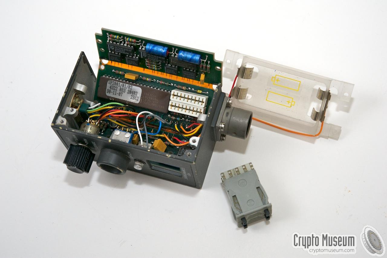
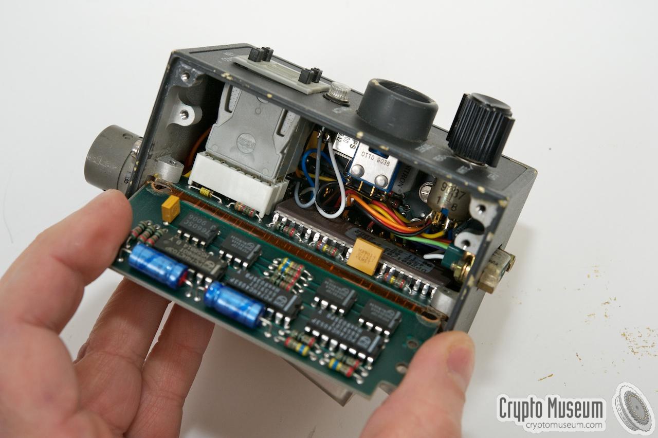
The body of the UP-2001 measures only 9.5 x 5 x 5.5 cm and is made of die-cast
aluminium, with a folded aluminium lid. The device can be opened by removing 4
2.5 mm screws from the lid, after which the battery compartment and part of the
main PCB is exposed. The device is powered by two Philips UP-6303 batteries of
3.6V each (7.2V total). These batteries have the shape of a standard penlight
battery. Good alternatives are available from Tadiran (TL-5104)
or Contrad Elektronik in Germany (EVE, order number 650773-89,
or Emmerich 651244-89).
|
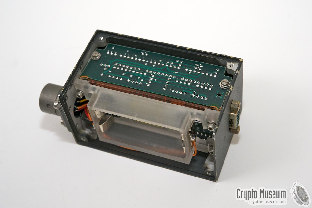
The main PCB consists of 3 (rigid) parts that are interconnected by integrated
flex PCBs. The entire flex-rigid construction can be folded in such a way that
it nicely fits the case. Each PCB is held in place by a set of 2.5 mm bolts.
The image on the right shows the opened UP-2001. The battery compartment and the
2-digit key selector have been removed (front right),
and the 3-part PCB has been folded-out. The center part holds the main
8051 microcontroller.
According to the label on the controller, the firmware was
released on 7 November 1990.
|
|
|
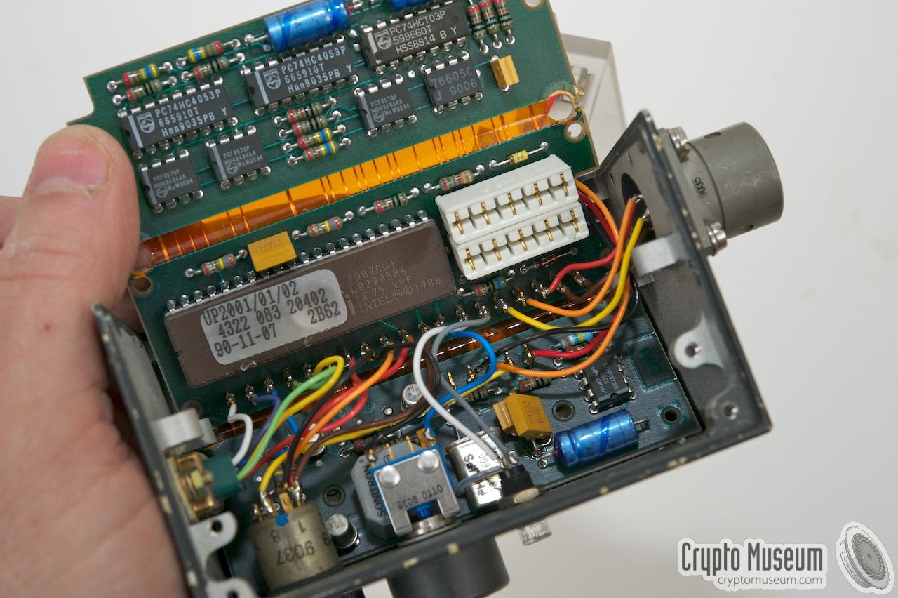
To the right of the controller is a pair of
(white) sockets that normally
hold the key selectors. Once the PCM is mounted inside the case, the key
selectors are inserted through a hole in the front panel and mate with the
white sockets on the center PCB.
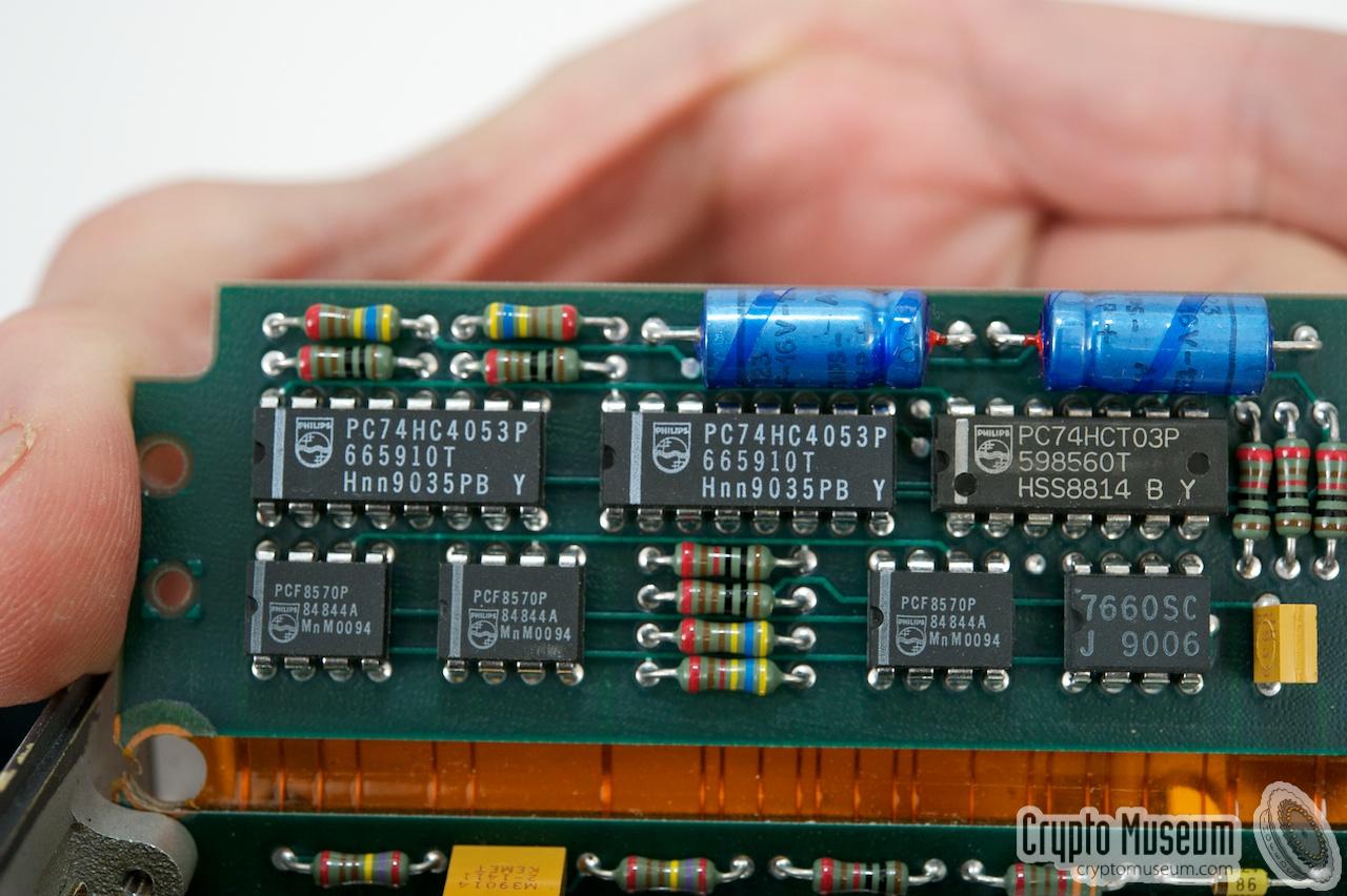
The upper board holds three PCF-8570P memory chips
that contain 256 bytes of low-voltage RAM each. This is enough to hold
40 keys of 128 bits each. The memory chips communicate with the
microcontroller via the I2C bus.
The lower PCB contains a MAX-666 power supervisor.
|
Connector DE9/S Protocol HP barcode reader, proprietary PC program Type Asynchronous Speed 9600 baud
|
- Remco Hopman, Philips UP-2001 - THANKS!
Donator of the UP-2001 featured on this page.
Eindhoven, April 2012.
|
|
|
|
Any links shown in red are currently unavailable.
If you like the information on this website, why not make a donation?
© Crypto Museum. Created: Wednesday 21 December 2011. Last changed: Thursday, 10 April 2025 - 20:38 CET.
|
 |

|
|
|


![Philips UP-2001 key-filler, kindly donated by Remco Hopman [2].](img/303069/001/full.jpg)