|
|
|
|
|

|
|
← Philips Text Lite EMU PX-1000 →
Portable communication terminal
The PX-2000 was a versatile pocket terminal,
introduced around 1985 by
Text Lite in Amsterdam (Netherlands),
as the successor to the PX-1000.
The device was intended for on-the-road word processing, calculations and
communication, and allowed encrypted messages to be sent over standard
telephone lines, using a built-in acoustic coupler.
In The Netherlands, the PX-2000 was sold by
Philips whilst in the rest of the world
it was marketed under the TEXT TELL brand name.
|
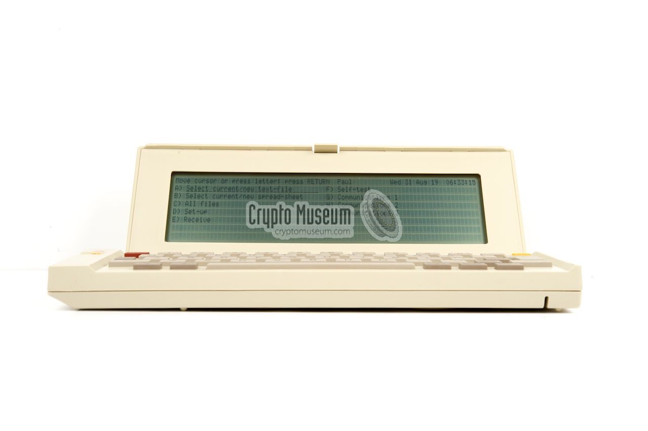
The image on the right shows a typical PX-2000 unit with its cream coloured
case, ready for use (i.e. with the lid open). The lid contains an 8 x 80
character display, which makes it far more suitable for word processing,
spreadsheet and terminal applications, than its
predecessor.
Apart from a word processor, a calculator, and a spreadsheet,
the PX-2000 has full
data and text encryption facilities built into its software.
Furthermore, it contains terminal emulations for DEC VT52, VT100, TTY,
VIDEOTEXT and others, allowing it to be used with a variety of services.
|
|
|
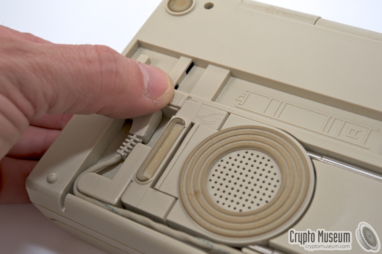
A full-duplex modem is available through the acoustic coupler at the rear of
the PX-2000. The coupler can be detached from the device, so that it can be
used easily with any telephone handset (see below).
The modem sends data at 300, 600 or 1200 baud, whilst
receiving simultaneously at 75 baud. The latter is used for the VIDEOTEXT
terminal emulation mode. The data format is 8N1.
The PX-2000 and its firmware was fully developed by
Text Lite BV
in Amsterdam (Netherlands), but was manufactured by Seiko (EPSON) in Japan.
It is backward compatible with the older
PX-1000, for which it supports simplex communication
at 300, 600 or 1200 baud, using the 7E2 2 data format.
This mode is called PX-1000 text mode [B].
When communicating with another device, the PX-2000 will detect the required
protocol from the header of the first data packet.
|
-
8N1 = 8 data bits, no parity and 1 stop bit.
-
7E2 = 7 databits, even parity and 2 stop bits.
|
The PX-2000 measures approx. 25.5 x 11 x 3.5 cm and is housed in a cream
plastic enclosure that consists of two halves: the actual computer with its
55 button keyboard, and a hinged top lid that contains an 80 character x 8 lines,
single colour LCD screen. A separate yellow SEND button is located to the
left of the top lid, so that can be accessed even when the top lid is closed.
The keyboard can be accessed by opening the top lid. The unit is switched
ON by setting the ON/OFF switch (at the right side) to the ON position and
pressing the yellow ON/STOP button at the top right. The device is fully
menu-driven. Special function can be accessed by using the red function key
in combination with any of the normal keys. This corresponds to the functions
that are printed above each key. The cursor control keys
are somewhat darker than the other ones.
|
|
As there were many different telephone (data) standards and requirements
at the time, Text Lite manufactured two variants of the PX-2000, each of
which was tailored for a particular country or communication standard.
At present, the following variants are known:
|
- PX-2000, version 1
This version is compatible with CCITT V23 and BELL 202 standards.
It supports both C-Mail and VIDEOTEXT emulation (1200/75 baud).
- PX-2000, version 2
This version is compatible with CCITT V21 and V22 standard, as well as
BELL 103 and BELL 212 standards.
This version can not send and receive messages from the Text Lite C-Mail
system, which requires the V23 standard (version 1). Furthermore, VIDEOTEXT
terminal emulation is not available in this version (as it also requires
the V23 standard).
|
|
The PX-2000 contains a flexible modem with an external acoustic coupler.
The modem can be used in simplex, half-duplex or full duplex mode.
In full-duplex mode it can only be used as a VIDEOTEXT terminal,
which was common in those days.
It allowed outgoing data to be sent at 75 baud, whilst receiving at 1200 baud.
In The Netherlands, VIDEOTEXT was known as VIDITEL.
|
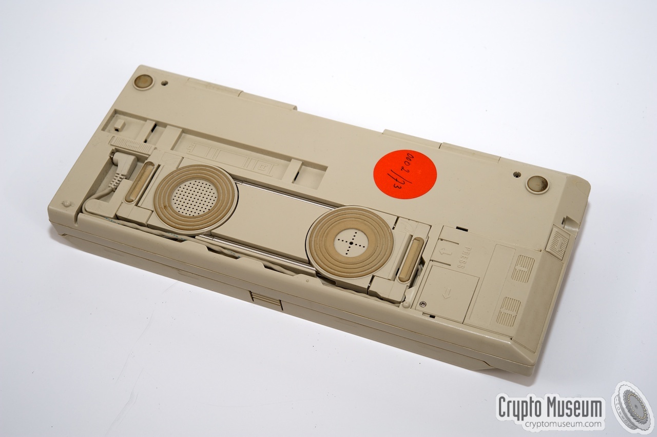
The acoustic coupler can be detached from the rear
of the terminal, and stays connected via a short cable with a 3mm jack
connector.
It has a microphone and speaker, that are separated by
two telescopic arms
which can be extended to match the size of the telephone's handset.
Furthermore, the microphone and the speaker are spring-loaded
so that they will automatically be positioned at the correct angle
for the handset in use.
Coupler and handset are usually kept together by means of the supplied
rubber clip. If it is missing, a rubber band can be used instead.
|
|
|
|
The PX-2000 has a fully implemented asynchronous RS232-compatible serial port,
which is available at the right side in the form of a
mini-DIN connector.
It allows speeds of 75, 150, 300, 600, 1200, 2400, 9600, 19200 and 38400 baud,
offering hardware handshaking (RTS/CTS) and software handshaking (XON/XOFF).
Baud rate, handshaking and data format are all under control of the user,
and a split baudrate (75/1200) is available for VIDEOTEXT.
The pinout is given below.
|
Each PX-2000 terminal has an exchangeable memory module that can be accessed
from the bottom side.
After unlocking it, it can be shifted sideways
and removed.
A row of gold-plated slide contacts, mate with the contacts
at the terminal's base.
External memory cards with a capacity of 8KB, 16KB or 24KB were available.
The card contains static RAM, which is retained by a small
backup battery on the card itself.
Replacing the battery is possible whilst the card is inserted into the
terminal and the terminal is powered by its batteries or other power source.
|
|
|
The images below show the interior
of the 8KB static RAM memory card.
The PCB can hold up to three 8KB meory chips, allowing 8KB, 16KB and 24KB
variants to be made using the same PCB.
The backup battery is in the
top left corner and is accessible through a lid in the enclosure.
|
If the device is not responding, despite the fact that the batteries are fully
loaded, it might be necessary to issue a Master Reset. This is
done by holding down both shift keys and then briefly pressing the ON/STOP
key. The device should then show the current firmware version number.
|
- 8 lines x 80 characters variable contrast LCD
- Exchangeable 8K, 16K or 24K static RAM memory module
- Simplex, half-duplex or full-duplex modem
- Detachable acoustic coupler
- RS232 compatible serial communications port
- Real-time clock with alarm
- Fully secure data encryption/decryption system
- Built-in word processor
- Spreadsheet and calculator facilities
- Rechargeable battery pack
|
- DEC VT-52
- VT-100
- VIDEOTEXT
- TTY
|
- Viditel (videotext)
- DataNet-1
- Telenet
- Telecom Gold
- Prestel (videotext)
- Transpac
- PSS
- Dialcom
- Memocom
- Datex-P
- Telepac
|
- CCITT V21
- CCITT V22
- CCITT V23
- BELL 202
- BELL 103
- BELL 212
|
The PX-2000 is capable of sending and receiving serial (RS232) data
at speeds up to 1200 baud full-duplex. At the right hand side is the
serial socket (i.e. the frontmost socket) that can be used for connecting
a computer, an external modem, a printer, etc. The 6-pin mini-DIN socket,
holds data-in and data-out signals and ground (GND), plus hardware handshake
lines (RTS and CTS). A 12V DC output is available for powering an external
device or interface. Pin-out is as follows:
Serial port (looking into the socket)
The power (charge) socket of the PX-2000 is located at the left side,
just below the SEND button. It accepts a small power plug, which a DC
voltage of 12V for powering the unit and/or charging the internal 6V
battery. Please note that the +12V should be connected to the ring.
Power connector (+12V at ring, GND at center pin)
The PX-2000 also has an AUDIO input and output, which are available
on a 3.5 mm jack stereo socket, loated at the right side of the unit.
It can be used for connecting a tape recorder and allows data to be
stored on an audio tape recorder and load it back later.
Audio input and output (3.5 mm jack)
|
|
Opening the case of a PX-2000 is rather difficult. First of all,
four small screws have to be removed from the bottom, two of which
are located under the acoustic coupler. Once these screws have been
removed, the top and bottom case shells can be separated, but four
internal plastic clips at the front will keep the two halfs together.
Use a small sharp object, such as a screwdriver,
to find the clips and wiggle it in between
the case halves, in order to unlock the clip.
|
The plastic clips are likely to break off as the plastic will
have become brittle over the years.
This should not be a problem however, and does not hamper the
PX-2000's operation in any way.
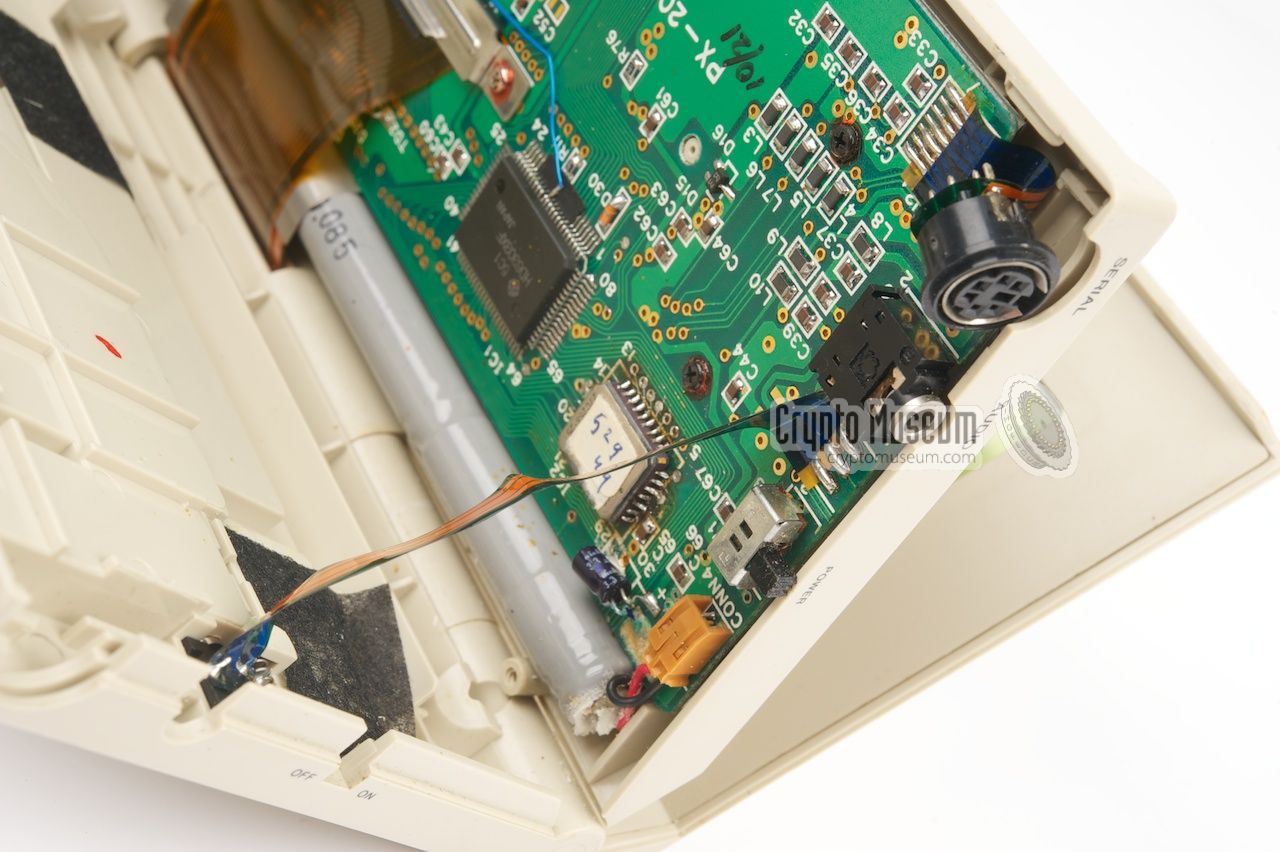
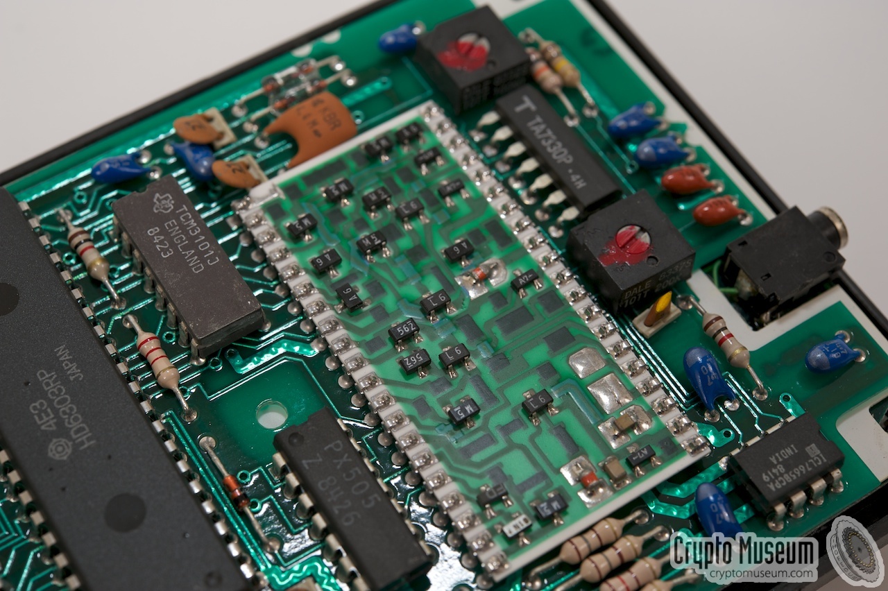
The device contains one large PCB with just five Integrated
Circuit (ICs) on it.
At the top left is the versatile
Hitachi HD6303X micro-controller
with an 27C256 EPROM to its left. This 32KB EPROM contains
the firmware of the unit. At the bottom center is a
Fujitsu MB62H168 CMOS Gate Array,
which contains 900 logic gates. Just above the gate array is a
RICOH RP5C15 real time clock.
|
|
|
At the top center is a flex strip that connects the PCB to the LCD screen.
To the right of the flex strip is a Texas Instruments TXC3105 of which
no datasheet has been found yet. It is probably a power supervisor.
The big black rectangular block at the top right, marked PX-2000,
is a custom-designed circuit block
containing the modem,
much like the custom module
in the PX-1000.
|
- COPYRIGHT 1985 WEST-TEC PX2000 Version E
- COPYRIGHT 1987 WEST-TEC Version G 29
|
- Text Lite BV, Text Lite PX 2000 Pocket Terminal
Full-colour leaflet (English), 2 pages.
- Philips Usfa BV, Text Lite PX-2000 Communication Terminal, Instruction Manual
User Manual (English), 84 pages, A5 size, B/W.
- PX-2000 Warranty Card
Orignal Warry Card (blank).
- Hitachi Semiconductor, HD6303X datasheet
Date unknown. Retrieved February 2014.
- Fujitsu Component Ltd., MB62Hxxx datasheet
Date unknown. Retrieved February 2014.
- RICOH Company Ltd., RP5C15 datasheet
June 1995. Retrieved February 2014.
|
- Cees Jansen (former cryptographer at Philips Usfa/Crypto)
Interview at Crypto Museum, August 2011.
- Hugo Krop, Personal correspondence and interview
Crypto Museum, 25 August 2013, 15 December 2013.
|
|
|
|
Any links shown in red are currently unavailable.
If you like the information on this website, why not make a donation?
© Crypto Museum. Created: Saturday 23 April 2011. Last changed: Wednesday, 24 August 2022 - 20:14 CET.
|
 |

|
|
|


![PX-2000 courtesy Cees Jansen [1]](img/301284/010/full.jpg)


