|
|
|
|
|

|
|
Motorola USA Phone STU-III SECTEL 3500 → ← 1500
The algorithm is selected by the information contained
on the KSD-64 Key Storage Device (KSD) which is
inserted at the right side. If the inserted KSD is a
Crypto Ignition Key (CIK), the SECTEL 2500 use
Type 2 encryption
when going secure.
If the inserted KSD-64 is a
Terminal Activation Key (TAK) or a Security Activation Key (SAK),
the Type 3 encryption
will be selected.
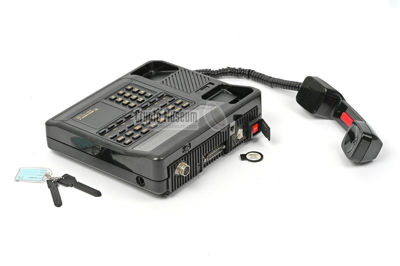
The image on the right shows a typical SECTEL 2500 unit in a fully
black enclosure. Its case is virtually identical to that of the other
SECTEL models and so are the controls and connections.
|
|
|
|
The Motorola SECTEL 2500 was primarily used by US Government agencies,
such as the FBI, DEA, ATF, etc. It was also used by the US Military,
Canadian defense agencies and some (approved) foreign government agencies.
The SECTEL 2500 itself in an unclassified device, but when used in
combination with a valid KSD,
it is classified to the level of the key.
The STU-III mode was phased out between 2005 and 2009,
after which the units were replaced by
Secure Telephone Equipment (STE).
From 31 December 2009, the STU-III mode of he SECTEL 2500
was no longer approved.
|
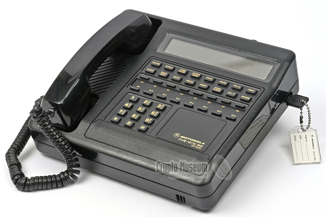
The image below provides an overview of the features of the SECTEL 2500.
At the rear are the connection to the outside world: the analogue PSTN
telephone line, the external power supply unit (PSU) and (optionally)
a computer. Also at the rear are backup battery and ZEROIZE button.
All user controls are at the top surface. At the top is a large LCD
with 16 function buttons below it, plus another 16 freely programmable
speed dial buttons. Towards the front is a regular telephone keypad with
the numbers 0-9 plus '*' and '#'. In rest, the handset is placed in the
cradle to the left of the keypad. For half-duplex operation, a special
handset with an integrated PTT button was seperately available.
Handsfree operation is possible, but not in secure mode.
|
|
SECTEL 2500 can be used in three different encryption modes, depending
on the requirements and the local possibilities. When using the STU-III
compatible mode, all key material is generated externally.
The following modes are available:
|
- STU-III
SECTEL 2500 is used in Type 2 encryption mode.
The required key material needs to be obtained from a COMSEC authority,
using the NSA-endorsed
FIREFLY protocol for
EKMS.
- Public Key
All key material is generated locally by the crypto custodian,
using the special Motorola KCA-3000 portable computer.
In this mode the device uses Type 3 encryption.
- Custom Mode
All key material is generated locally by the user on the phone's keypad.
It is then stored on a KSD in order to be transferred to other SECTEL
2500 phones. In this mode the device uses Type 3 encryption.
|
Key material is generated externally and loaded into
the SECTEL 2500 by means of a so-called Key Storage Device (KSD),
such as the KSD-64A
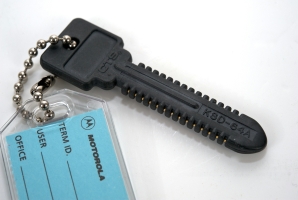
manufactured by Datakey Inc.
It looks like a plastic toy key and works like starting a car.
The KSD can be used for a variety of purposes.
such as: Crypto Ignition Key (CIK), Master CIK, FILL Key (FK),
Terminal Activation Key (TAK), Security Activation Key (SAC)
and Traffic Encryption Key (TEK).
➤ More about the KSD-64
|
|
|
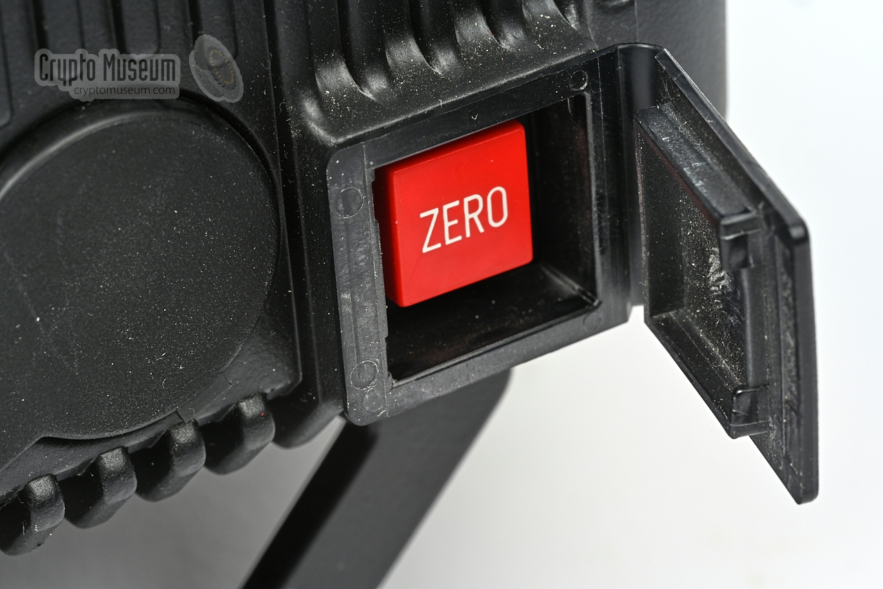
When security is compromised, the keys inside the STU-III have
to be purged immediately. By convention this is always a two-step
or double-action procedure, such as pressing two buttons
simultaneously.
On the SECTEL 2500 it involves
opening a plastic door at the rear
and pressing the red button
– marked ZERO – behind it.
Once the device is zeroized, it can no longer be used in secure mode,
until new keys are loaded.
|
|
|
At 2400 baud, the SECTEL 2500 uses a 2.4 kbps Linear Predictive Coding
algorithm known as Enhanced LPC-10 or LPC-10e.
It is based on the FS-1015 or STANAG-4198 standard [A].
The same standard was used in other crypto phones from the same era,
such as the Philips PNVX,
the Philips Spendex 40,
the AT&T 1100 (later: Lucent and General
Dynamics), and the American CVAS-III.
The LPC-10e algorithm is suitable for half-duplex as well as full-duplex.
At 4800 baud, Code-Exited Linear Predictive Coding (CELP)
is used in full-duplex, providing better audio quality.
At the highest speed, 9600 baud, an even better algorithm —
Modified Residual Exited Linear Predictive Coding (MRELP) —
is used in full duplex.
The SECTEL 2500 has a built-in V.24/V.32 modem that can also be used
for computer data at baud rates ranging from 75 to 9600 baud.
It is tested and compliant with virtually any telephone network in the world.
If the quality of the (foreign) telephone line is below average, the
system gracefully degrades to a lower speed, but maintains its Type 2
cryptographic security.
|
A STU-III telephone can be connected to any standard analog telephone line
(POTS/PSTN).
A call is always initiated in clear (non-secure) mode. In order to
go secure, both parties have to insert and activate their unique
Crypto Ignition Key (CIK).
Then, one of the parties initiates the secure conversation by pressing the
Secure button.
After a 15-second delay, during which the message keys are exchanged
and the phones are synchronised, a secure conversion is possible.
The 10 to 15 second delay is common for all STU-III phones and can be
considered a nuisance to the user. Furthermore, valuable information is
often given away in the clear voice conversation that takes place
before secure mode is entered.
This delay did not occur with the later STE phone.
Until today, there have been no reports of STU-III units being broken.
That does not mean, however, that foreign intelligence services did not
gather valuable information from intercepted lines, directly before
and after the secure part of the conversation and from the metadata.
|
Due to its analogue interface, the STU-III could be used virtually
anywhere in the world. When the US President (POTUS)
went on a (foreign) trip, the Scret Service installed two STU-III
phones at any location POTUS might visit that day, so that he could
immediately contact his staff in case of an emergency.
The STU-III was used by no less than four US Presidents (POTUS):
Ronald Reagan, George H.W. Bush (Sr), Bill Clinton and George W. Bush (Jr).
➤ Images of POTUS using a STU-III
|
|
|
The heart of the system is the Motorola SECTEL 2500, which is STU-III
compatible. It can be used in STU-III mode in which it is interoperable
with other STU-III devices, such as the SECTEL 1500,
both of which are then used in Type 2 mode.
It can also be used in non-STU-III mode in which it uses DES; a Type 3
algorithm. In this mode it is compatible with the SECTEL 3500.
➤ Look inside the terminal
|
|
|
|
|
Key Storage Device
KSD-64
|
|
|
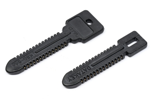
Key material is stored on a KSD-64 Key Storage Device
manufactured by Datakey in Savage (Minesota, USA).
It is a 64Kb EEPROM in the shape of a plastic toy key. The KSD-64 was later
replaced by the compatible PK-64. Two keys were supplied with
each SECTEL 2500 unit.
Once a valid key is loaded into the terminal, the KSD-64 is converted into
a Crypto Ignition Key (CIK) and is paired with the terminal. From that
moment on, the terminal can not be used in secure mode when the CIK is
not present.
➤ More information
|
|
|
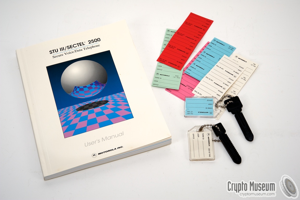
Each SECTEL 2500 terminal was supplied with the Operating Instructions
shown in the image on the right. It describes how the terminal should
be used in a Type 2 (STU-III) or Type 3 (DES) environment.
It also explains the various user menus that are accessible via the display.
➤ Download the manual
➤ Quick reference card
|
|
|
To suit the safety requirements of the customers as well as US Government
regulations, different SECTEL models were manufactured, all based on the same
basic hardware design and enclosure. The firmware and the cryptographic
algorithms are different however. The diagram below shows how they
are positioned. Only the SECTEL 1000 series and
2000 series are STU-III compatible.
Click any of the balloons above for additional information about the
related SECTEL model. The SECTEL 2500 is interoperational with all
SECTEL 1000, 2000 and 3000-series devices,
including the SECTEL 1500 and 3500.
When communicating with a 1000-series device, it is used in Type 2 mode.
When communicating with a 3000-series device, the SECTEL 2500 is used
in Type 3 mode.
|
|
The device is housed in a rectanglular enclosure that consists of
two parts: a die-cast aluminium bottom part, with a plastic part on top.
The interior can be accessed by removing four security torx screws from the
corners of the bottom, after which the two case halfs can be separated.
|
Inside the device are three large printed circuit boards (PCBs) and two
smaller daughter cards. The first large PCB is fitted inside the plastic
upper case shell. It contains all parts for the user interface: keyboard,
display, microcontroller and firmware. The upper part also contains a speaker
— used in handsfree mode — a small buzzer (used as a ringer) and
the cradle for the handset.
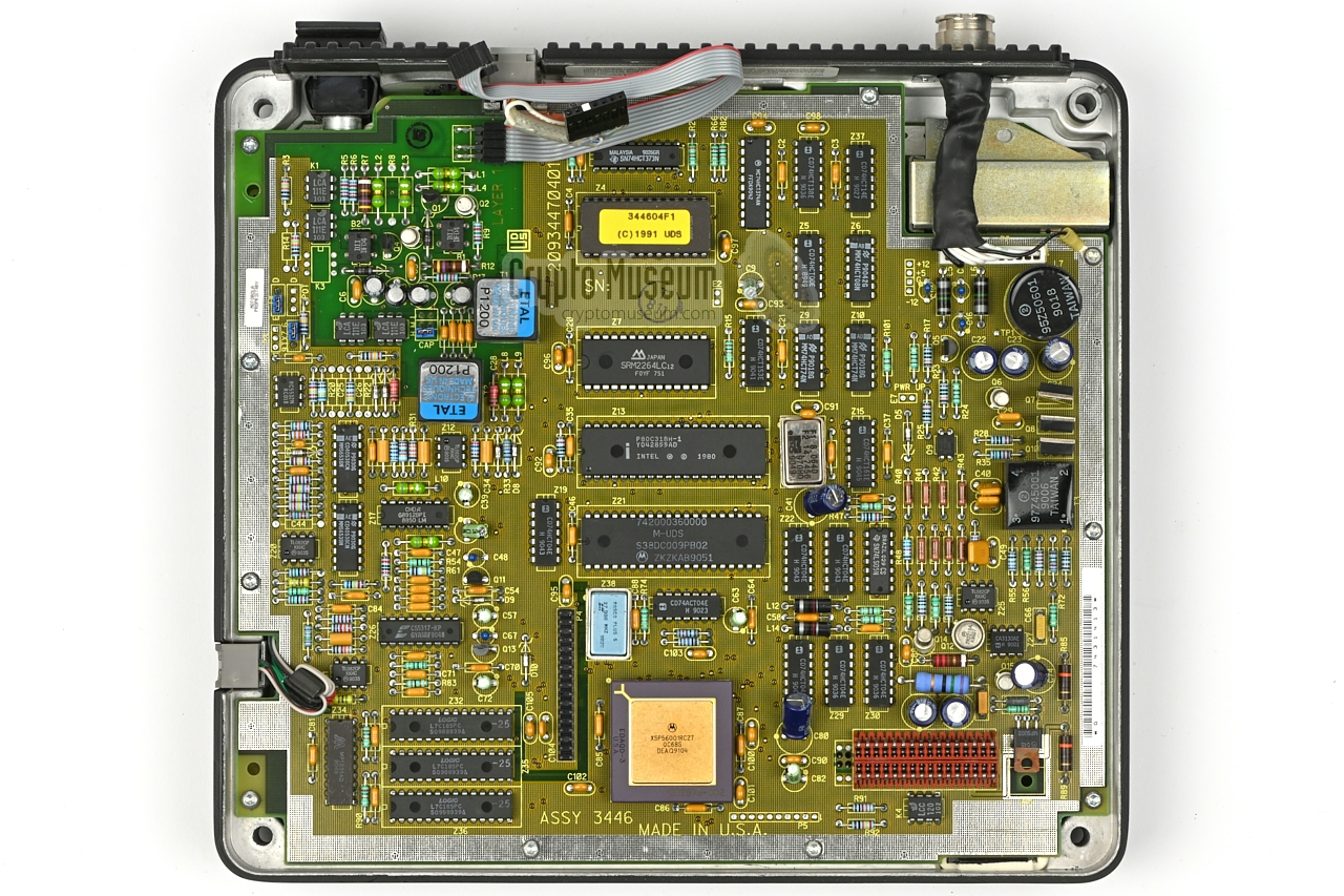
The top PCB is shown in the image on the right. It is connected to the
bottom half by means of two flatcables and two flying leads, that must
be disconnected when separating the case halfs.
|
|
|
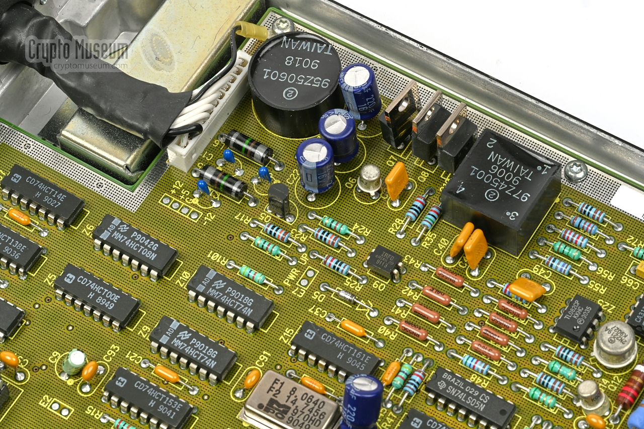
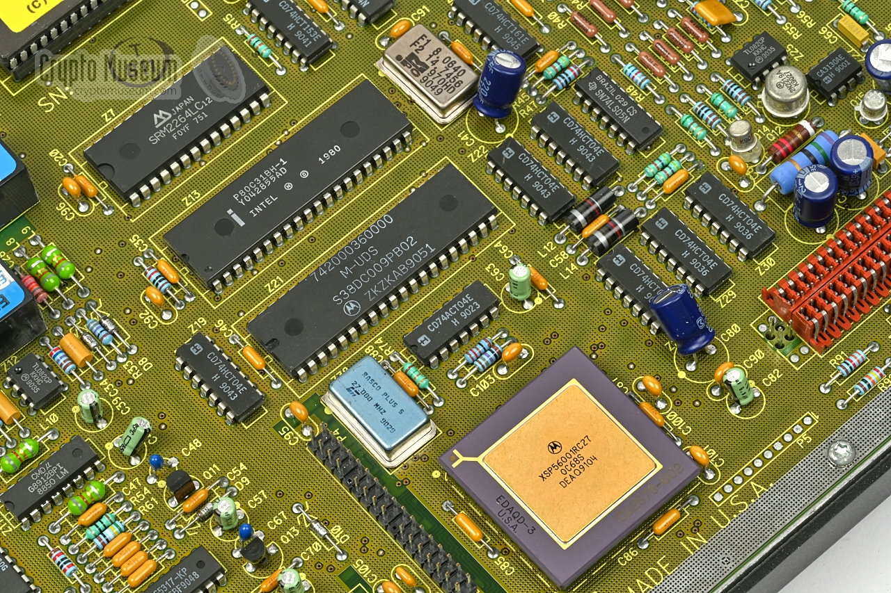
The power circuit is at the far right. It is fed by
the +12V, -12V and +5V lines from the external power supply unit
(PSU) and provides the correct voltages for the analogue and digital
circuits.
The telephone circuit is located at the top left.
It is galvanically isolated from the
rest of the circuits by means of special ETAL transformers.
The vocoder consists of an Intel 8031 processor with RAM, EPROM
– with firmware – and a Motorola 56001 Digital Signal Processor (DSP),
which had just been introduced in 1986 [2].
|
|
|
|
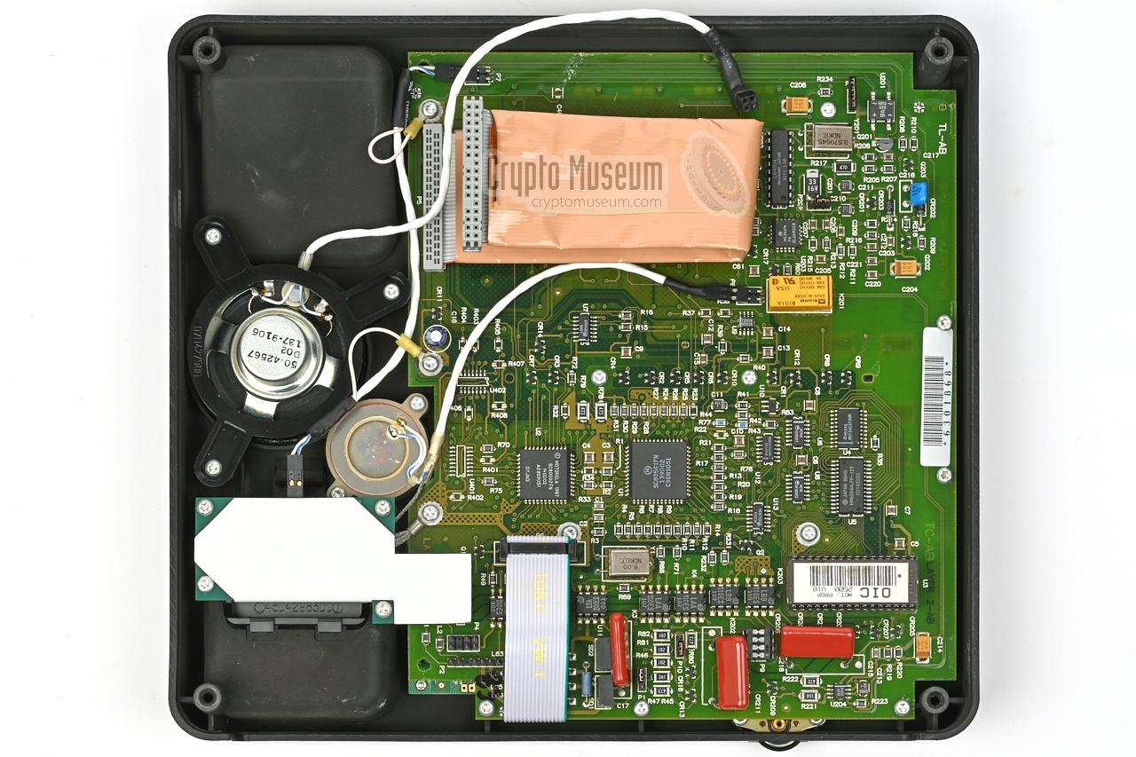
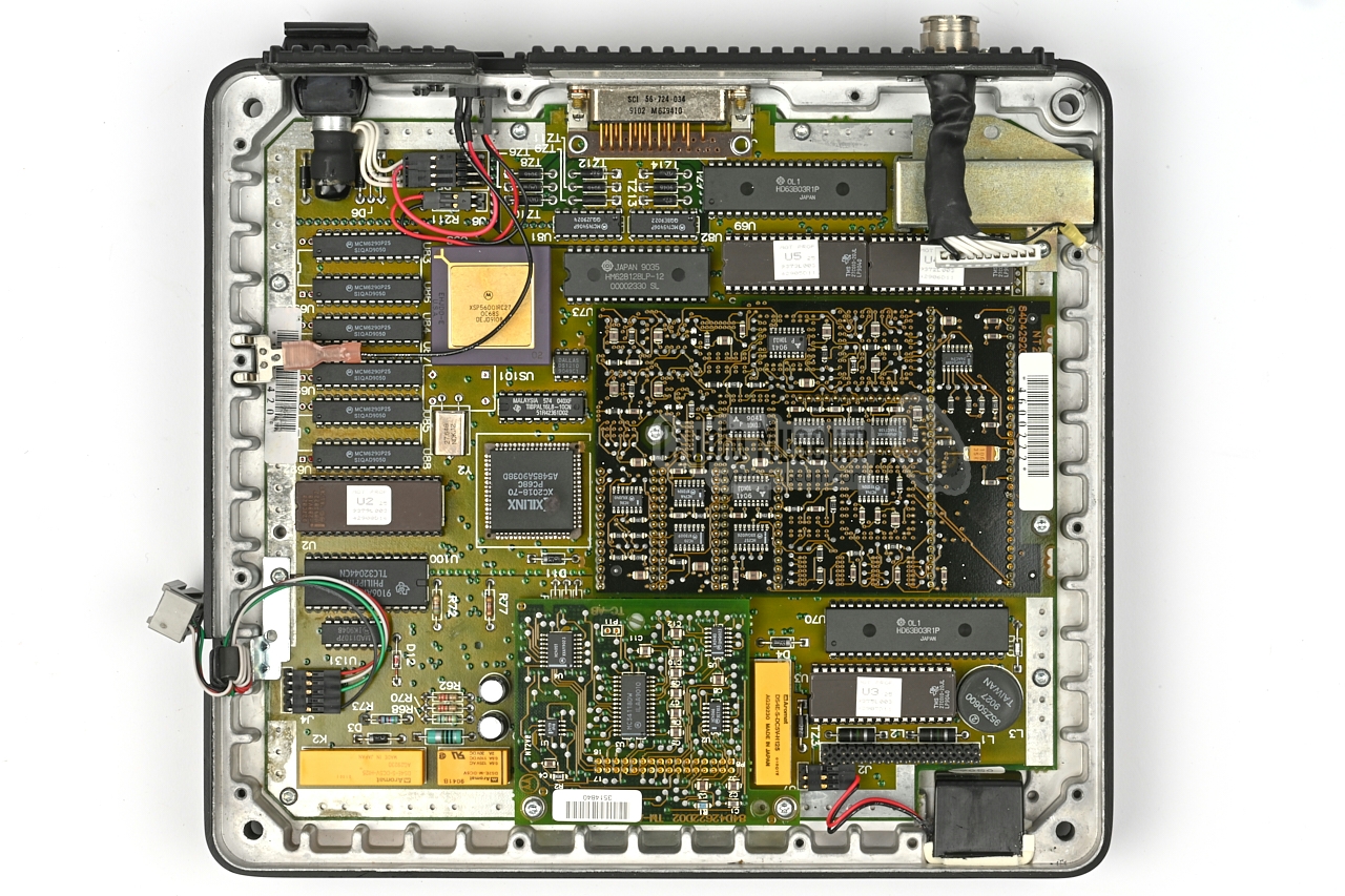
The board is connected to the third large PCB at the bottom of the
case shell by means of a red interboard connector at the bottom right.
It can be removed by removing 11 screws from the edge of the PCB,
disconnecting the power wiring at the top right and lifting the board upwards.
|
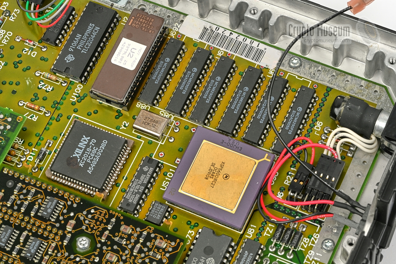
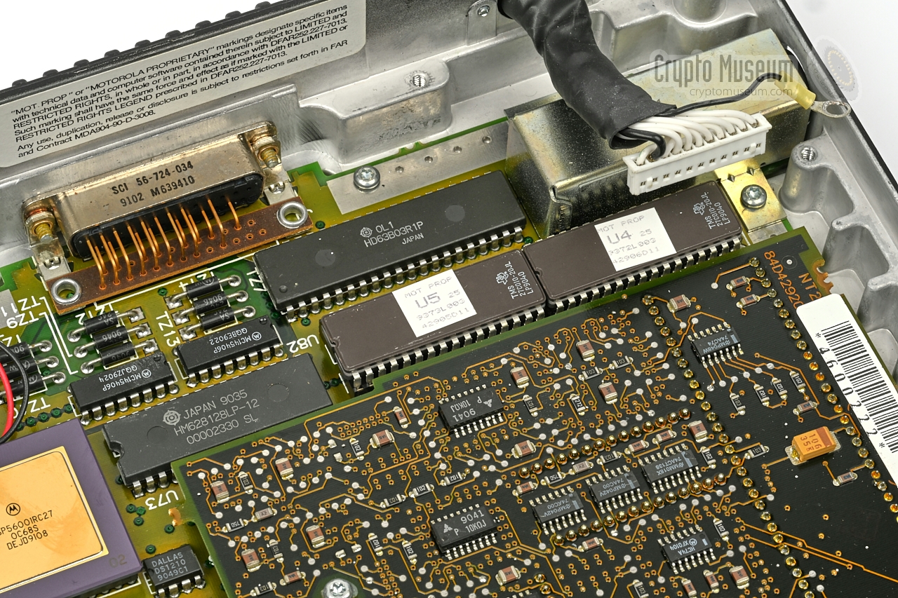
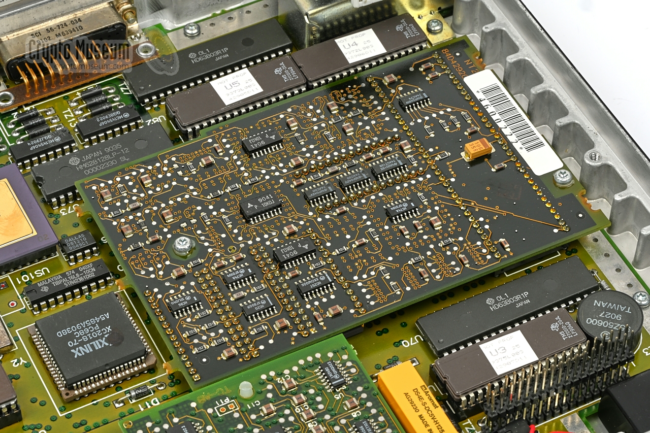
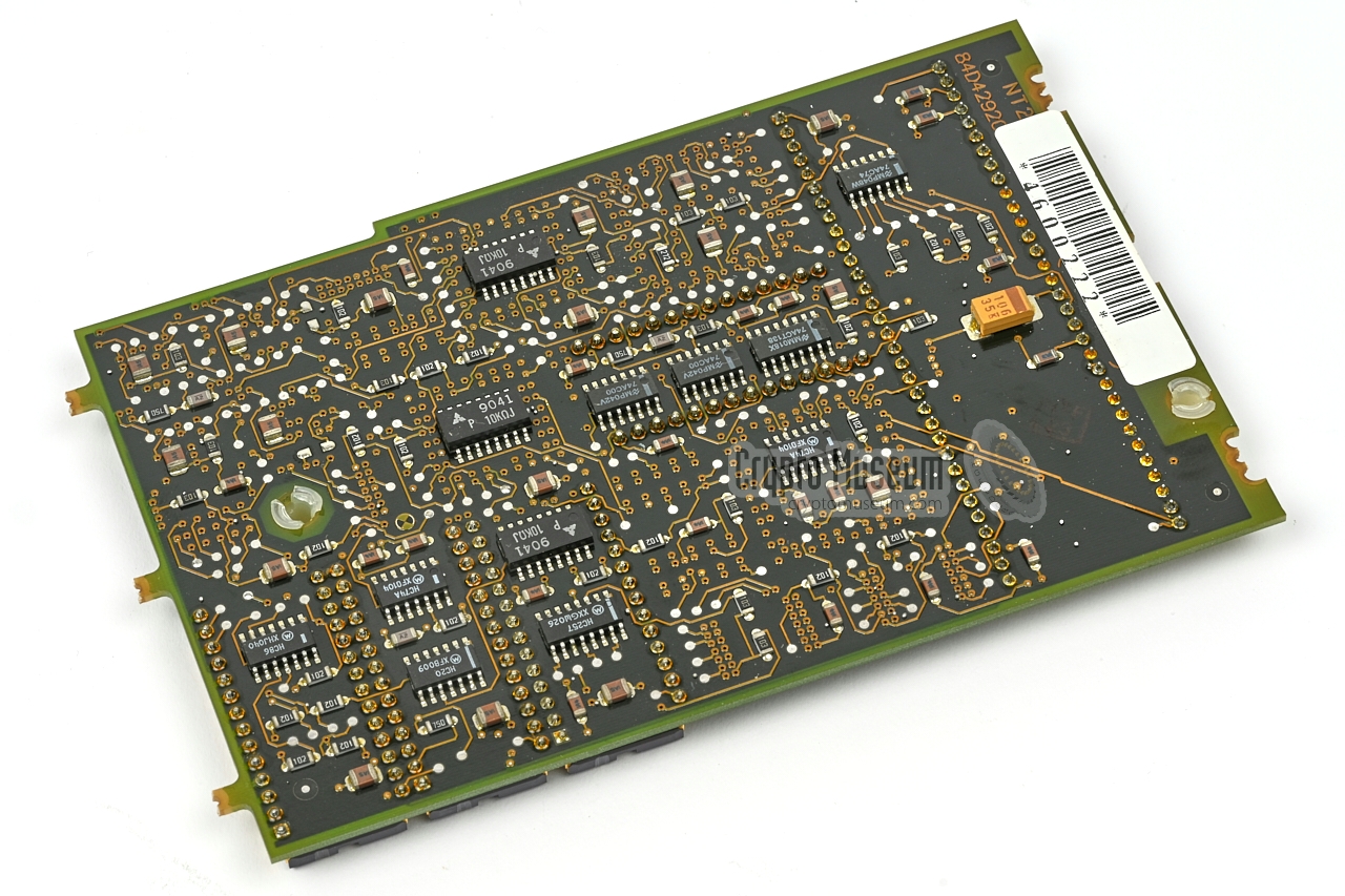
This reveals the bottom PCB. It contains the other half of the LPC-10e
/ CELP / MRELP vocoder, which consists of
two Hitachi 6303 processors with RAM, EPROMs and one Motorola
56000 DSP. It also holds a XILINX XC2018 Field Programmable Gate Array (FPGA)
with firmware.
At the centre of the bottom PCB is a daughter card
which is mounted upside down. It is the key generator or crypto heart in
which the secret cryptographic algorithm is implemented in custom chips. The
crypto heart is connected to the bottom PCB via a large 64-pin Dual-in-Line
(DIL) socket, and is held in place by two screws.
|
|
|
|
The crypto heart has components at both side of the PCB The
side that is visible in the image above
(the bottom of the board) contains some glue logic. After removing the two
screws, it can be lifted from the 64-pin socket.
This has to be done carefully to avoid bending the contact pins.
|
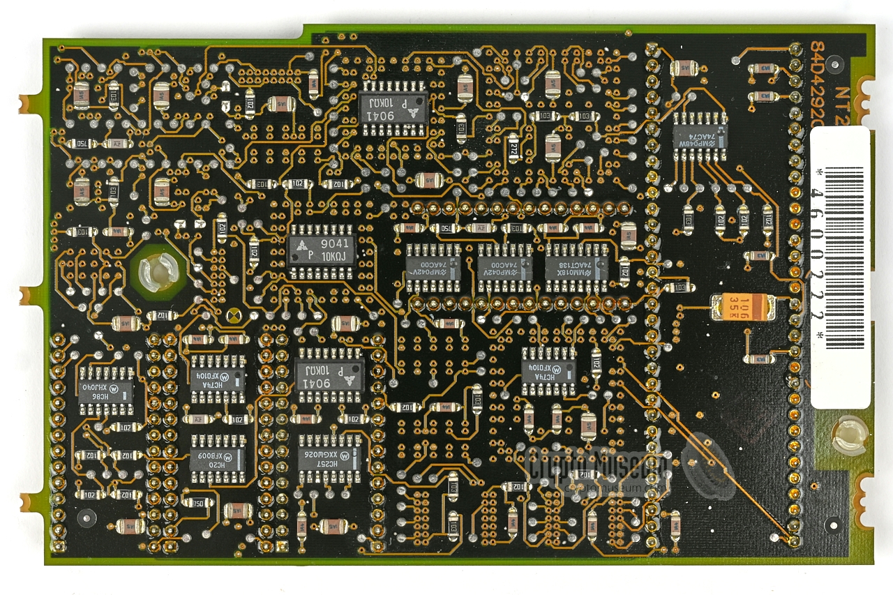
After turning the board over, the
top side becomes visible as shown
on the right. A the right are the pins of the 64-pin DIL connector.
At the top left are
three Motorola ON408219 custom chips
which contain the secret Type 2 algorithm. One of these is used for the
reception circuit, whilst the other two are for two identical transmission
circuits. The outputs from the two transmission circuits are constantly
compared and an alarm is raised as soon as a difference is detected.
To the right of the three crypto chips is another
Motorola custom chip: ON393570.
|
|
|
|
The rest of the board is taken by a XILINX XC2064 FPGA with firmware in
EPROM, in which the device's second algorithm — DES — is implemented.
This second algorithm is selected when the device is used in Type 3 mode.
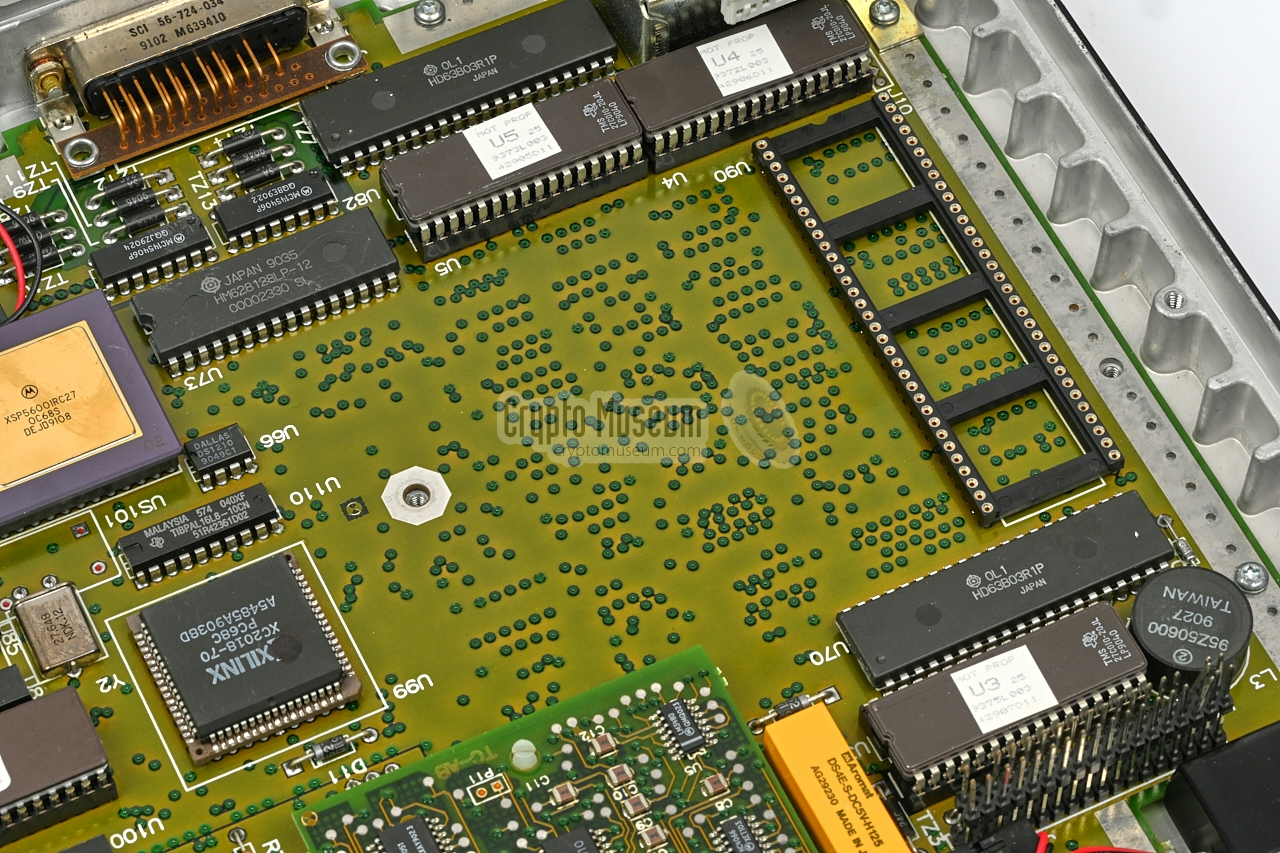
Note that the crypto heart is often missing from devices sold on on public
auction sites such as eBay. This is done as part of the declassification
procedure.
|
|
The SECTEL 2500 phone is powered by an external Power Supply Unit (PSU)
that provides three different voltages: +5V (1.75 A), +12V (250 mA) and
-12V (210 mA). The PSU is connected to the 7-pin (or 8-pin) 270° DIN
socket at the rear of the unit. The socket has the following pinout:
|
- +12V
- -12V
- +5V
- 0V (GND)
- 0V (GND)
- +5V
- 0V (GND)
|
|
|
At the rear of the device is a 6-pin
RJ-25 (6P6C) modular socket
for connection to a 2-wire or 4-wire subscriber line.
When connecting to a 2-wire line, an RJ-11 connector can be used,
as only the middle two contacts (3 and 4) are needed.
The pinout is as follows:
|
|
At the rear of the device is a 25-pin DB25 socket for connection to an
external device such as a Personal Computer (PC). The socket is wired
to the common RS232 standard and carries the common data and modem signal.
The SECTEL unit support the AT-command set (like a modem).
|
- Protective Ground (shield)
- Transmitted Data (TXD)
- Received Data (RXD)
- Requesst to Send (RTS)
- Clear to Send (CTS)
- Data Set Ready (DSR)
- Signal Ground (GND)
- Data Carrier Detect (DTD)
- Data Terminal Ready (DTR)
|
|
Device Secure voice terminal Purpose STU-III voice communication Model SECTEL 2500 Type STU-III Family SECTEL Manufacturer Motorola Years ~1991 - 2009 Country USA Users US Government, FBI, DEA, ATF, contractors Algorithms Secret NSA Type 2, DES (Type 3) - RJ25 (RJ11)
Voice 2400, 4800, 9600 1 baud Data 75, 110, 330, 600, 1200, 2400, 4800, 9600 baud Interface RS232 Vocoders LPC-10e (2400 baud), CELP (4800 baud), MRELP (9600 baud) Encryption NSA Type 2, Type 3 (DES) CIK KSD-64 Power 90 to 250V/AC, 47 to 63 Hz Temperature 0°C to +50°C Storage -10°C to +70°C Humidity 90% (non-condensing) TEMPEST MIL-STF-461B (RS03) Dimensions 229 × 254 mm × 64 Weight 4 kg Quantity ? Price USD 2145 (1991), USD 3395, other
|
- SECTEL 2500 voice/data terminal
- Handset
- Coiled cable for handset
- TELCO line cable (6-wire)
- Power supply unit
- Mains power cable
- User manual
- 2 × KSD-64 Crypto Ignition Key (or equivalent)
|
- RJ11/RJ45 adapter
- Single-line surge protector
- Cosmetic repair kit
- Push-To_Talk handset
- Carrying case
- Wall mount bracket
|
-
At 9600 baud, Motorola SECTEL terminals are not interoperable
with the STU-III telephone sets from other manufacturers.
At that speed the MRELP codec is used, which is a proprietary
Motorola development.
|
|
|
|
Any links shown in red are currently unavailable.
If you like the information on this website, why not make a donation?
© Crypto Museum. Created: Sunday 11 July 2010. Last changed: Monday, 23 September 2024 - 09:09 CET.
|
 |

|
|
|