|
|
|
|
|

|
|
Data Mils
Automatic cipher machine
- under construction
The 5010 was an electromechanical automatic
cipher machine,
developed by
Reichert Elektronik in Trier (Germany) 1
in the early 1960s. The device is
intended for the encryption and decryption of signals from an electric
IBM typewriter and an external tape puncher/reader and/or a printer.
|
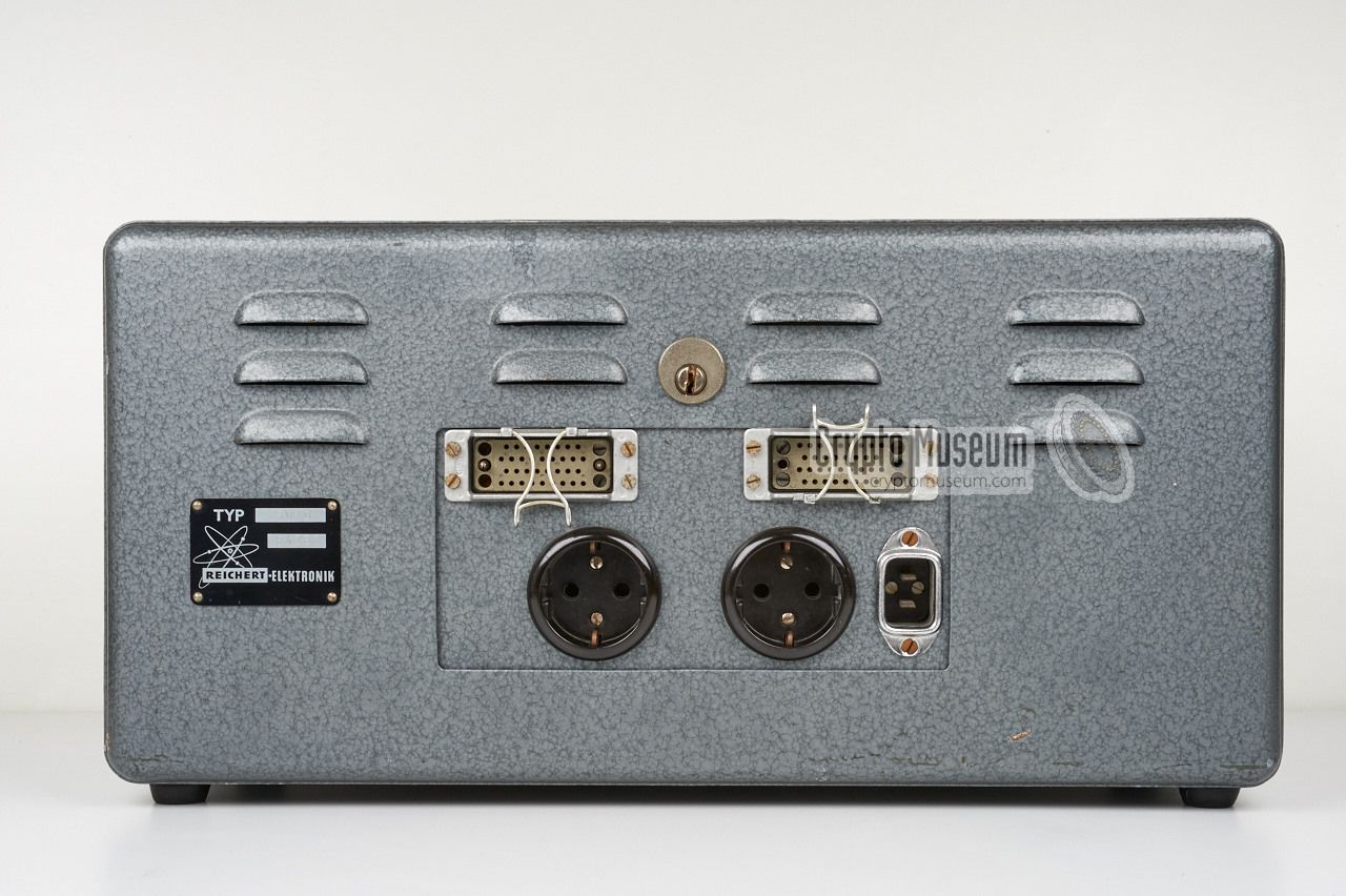
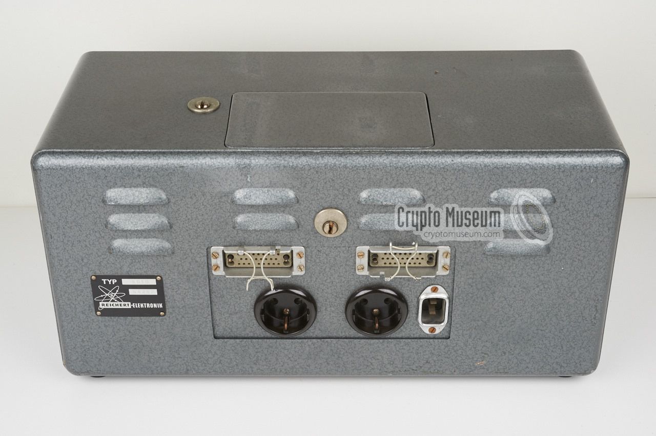
The image on the right shows the extremely rare Reichert 5010.
It has two physical locks: one at the top that locks the lid to the
two plugboards, and one at the rear that prevents the case from being
opened. As the original keys are missing from the device shown here,
we had to pick both locks in order to gain access to the interior.
At the rear are two Harting 34 pin female sockets for the input and output
devices. The leftmost one was probably used to connect an IBM electric
typewriter, whilst the rightmost one accepted Reichert's Datica 100 tape
puncher.
|
|
|
The machine has two user-configurable plugboards, one for the input
and one for the output, that can be accessed through a lid at the top.
Furthermore, the machine has four 26-position rotary switchs
(marked A, B, C and D)
that are used for setting the basic key, plus an internal revolving
plugboard that can be configured by a priviledged user or an engineer.
In addition, there is a uniselector and 5 electric relays of which
the function is currently unknown.
|
-
Rechert Elektronic was later known as
Mils Electronic and was located
for many years in Mils (Austria). The company was dissolved in 2018.
➤ More
|
|
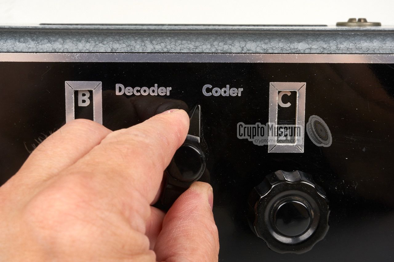
The upper half of the machine's front panel holds 4 rotary switches
with 26 positions each.
Only half the number of positions are used in each mode: 13 for coding,
interleaved with 13 positions for decoding. Above each knob is a window
that shows the current setting. In Coding Mode, the knobs are marked
A, B, C and D, whilst in Decoding Mode they are marked C, D, A and B.
These four rotary selectors are used for setting the basic key.
|
At present, the exact operation of the 5010 is unknown.
Whilst we are investigating the machine we are gradually beginning
to understand how it works, but this process has by no means been
completed yet. The block diagram below gives a snapshot of the current
situation.
|
|
|
|
Any links shown in red are currently unavailable.
If you like the information on this website, why not make a donation?
© Crypto Museum. Created: Wednesday 10 August 2016. Last changed: Wednesday, 27 October 2021 - 09:33 CET.
|
 |

|
|
|