|
|
|
|
|

|
|
Data Gretag DES SWIFT
Highly secure encryptor for SWIFT payments
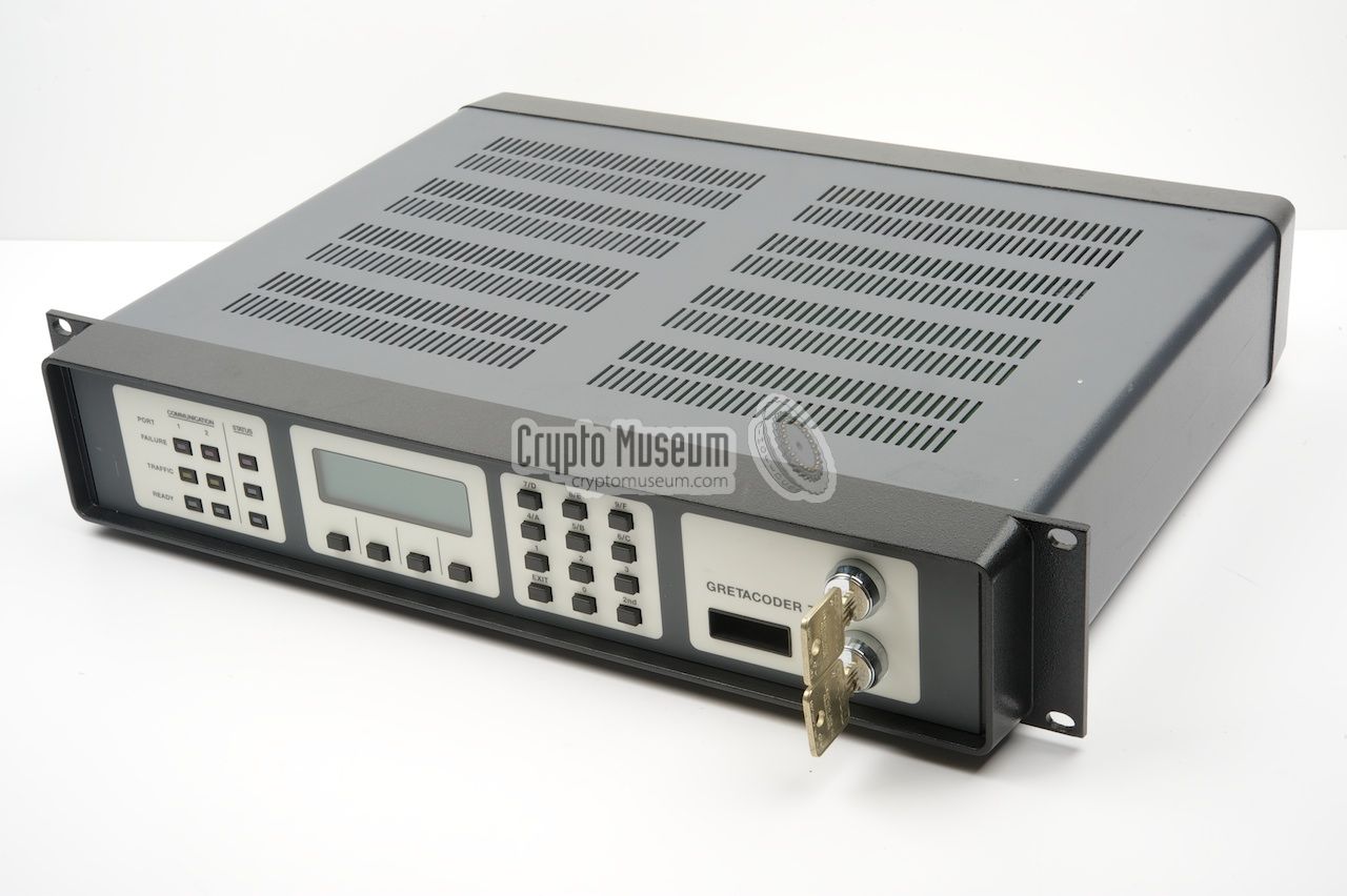
Gretacoder 720, was a highly secure DES-based encryption/decryption
system, developed in the late 1990s
by Gretacoder Data Systems
(formerly: Gretag) in Regensdorf (Switzerland).
It was the successor to earlier data encryptors, such as
the the Gretacoder 515 and the Gretacoder 715,
and was used on the worldwide secure and trusted interbank
financial communication system SWIFT.
|
The device is housed in a strong and tamper-free/evident
2U 19" rackmount enclosure that is
extended at the front. All controls are at the front panel, including
two physical locks and a display, whilst all connections are at the rear.
The encryption device itself is mounted inside a
metal frame that is mounted to the rear of the front panel.
It can only be removed when both keys are inserted and
turned by 180 degrees. In addition, the GC-720 has a range of
tamper sensors and other security measures,
to protect the device and the stored cryptographic keys.
|
|
|
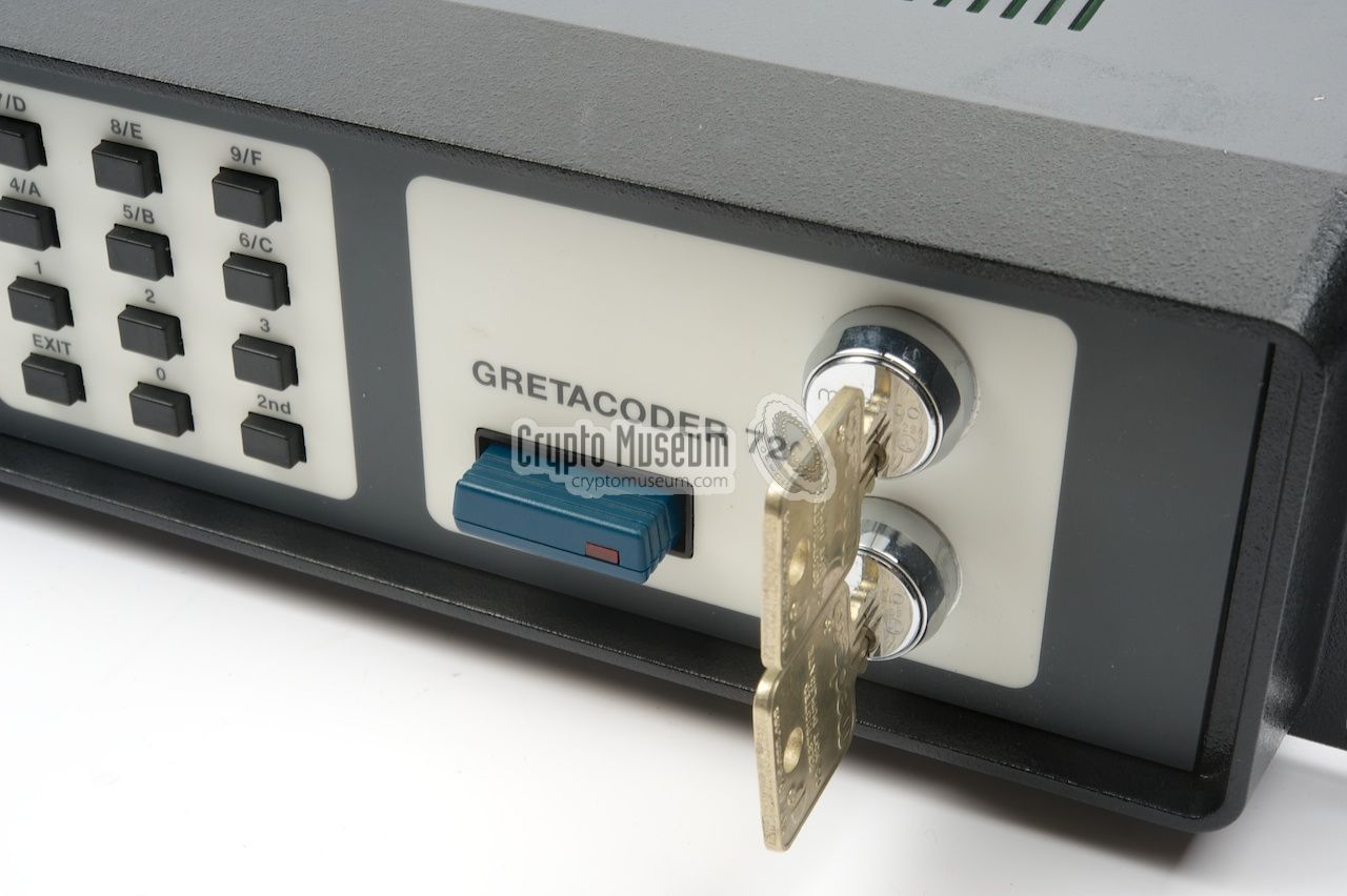
All controls are at the front panel
of the Gretacoder 720.
The device is activated by connecting it to the mains and turning
the two keys at the right. Furthermore, a suitable
external key module must
be present in the slot to the left of the lower key.
To the left of the keys is a keypad with 12 buttons, used
for entering cryptographic keys and parameters. To its left is a
4 x 20 character LCD.
Below the display are four function keys.
At the far left are 9 status indicators (LEDs).
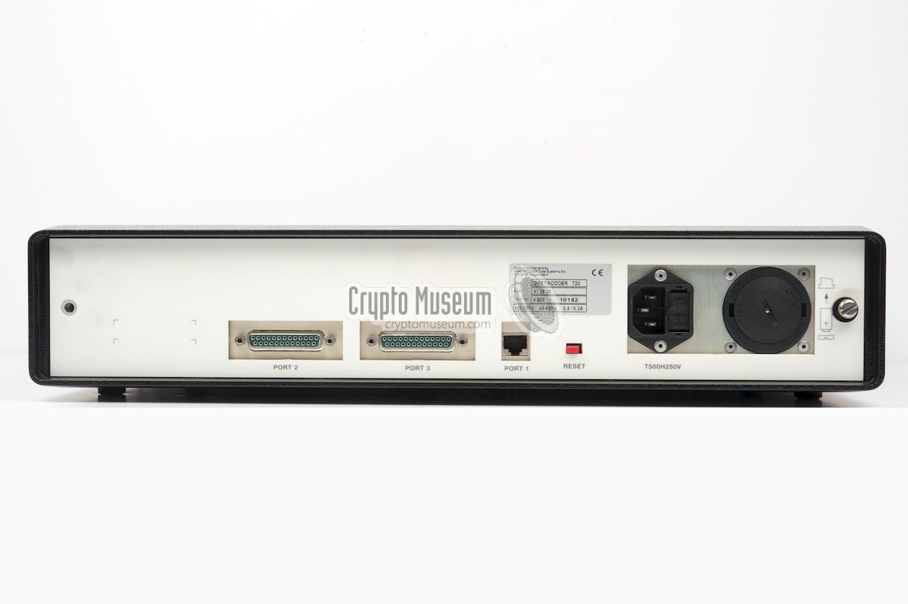
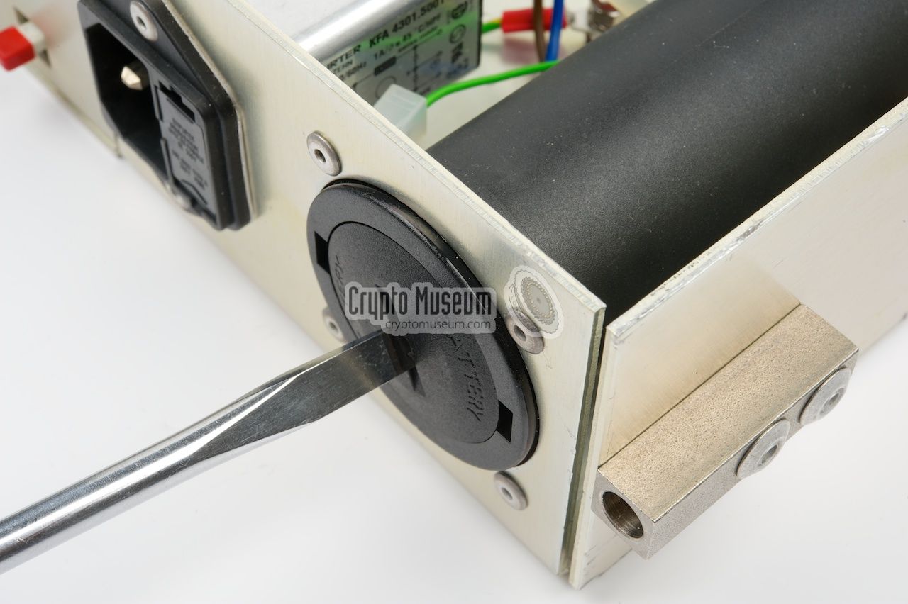
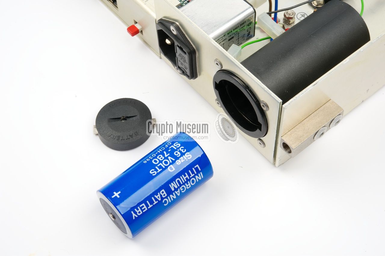
All connections are at the rear.
At the left are two
25-pin D-sub
sockets for connection to the RS232 or X.25
input and output ports, plus a
10/100Mb ethernet socket.
To the right of the ethernet socket is a small red RESET button.
At the right are the mains socket and a removable 3.6V Lithium
backup battery that can be replaced when the device is operational.
The sockets are actually mounted to the internal frame and protrude
the rear panel of the outer case shell.
|
|
The Gretacoder 720 is extremely well built and is housed in a strong
heavy metal 2U 19" rackmount case. The actual device is mounted in a
subframe that is mounted to the rear of
the front panel. In order to protect the device againt tampering,
a lot of safety features are present.
|
The subframe with the front panel and the electronics can only be
removed from the outer case, by releasing the two bolts at the edges of
the rear panel, and turning both physical keys at the front panel.
The sub frame can now be removed from the outer shell.
It is shown here.
The first tamper protection is a small switch
that is mounted to the rear of the sub frame.
When removing the sub frame from the outer shell,
this switch causes the crypto keys to be purged. The actual keys are stored
in volatile static RAM that is retained by a
large 3.6V Lithium battery.
|
|
|
|
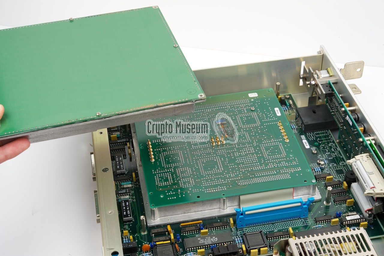
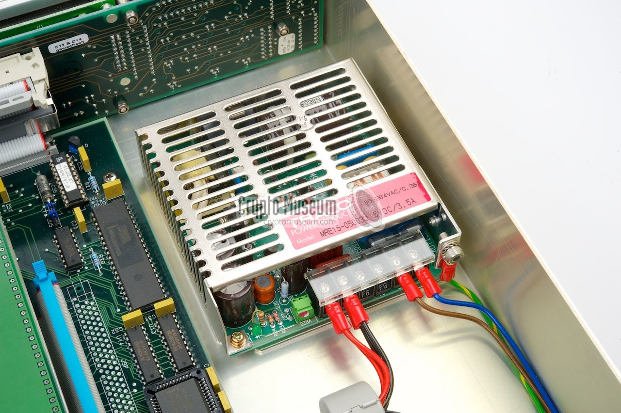
The device roughly consists of 4 parts: a small
industry standard power supply unit (PSU),
the main board, a large crypto unit (the large green square),
and the front panel.
The main board takes up most of the case and contains only the interface
circuits such as the RS232 ports. All connectors at the rear are mounted to
the main board. The front panel is also connected to the main board, via
a ribbon cable with ferrite clamp
(in order to meet EMC requirements).
|
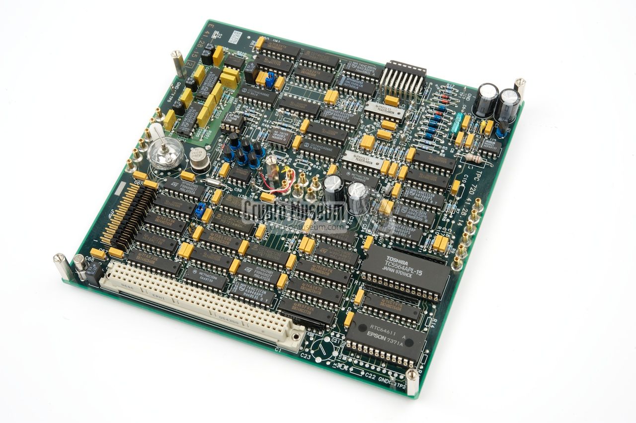
But the most interesting part is the large green square.
This is the crypto unit or crypto heart.
It consists of two boards, marked HOST 720 and TPC 720,
that contain the main processor, a dedicated DES encryption chip,
a CPLD, various special circuits and some additional 'glue logic'.
The crypto unit is mounted inside an extremely well protected die-cast
aluminium enclosure that consists of a bottom shell and an overlapping top shell.
It is connected to the main board via only one ribbon cable.
The top shell is removed
by releasing the four bolts at the corners.
|
|
|
|
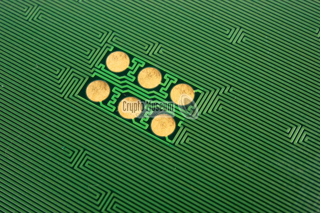
After removing the
top shell of the crypto unit, the next anti-tamper measure becomes visible.
At the inside of the top shell is a PCB with a
complex labyrint of copper tracks,
known as a meander.
Several different signals are routed in a seemingly random manner over the
board. The board is connected to the actual crypto boards via a series of
contact pads at the center and at the edges.
|
Breaking or shorting any of the signals that are running over the meander
tracks, causes a tamper alarm and will purge the cryptographic keys instantly.
The image on the right shows the contact pads at the center of the top shell.
These pads mate with a set of spring-loaded contacts
at the center of the upper crypto board.
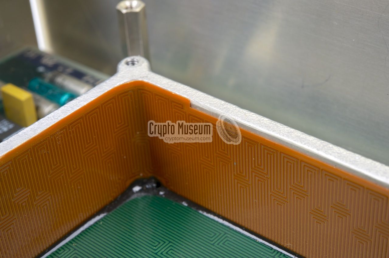
Similar meander patterns are also found
at the inner sides of the top shell.
They are constructed from orange foil with copper tracks (flex PCB) that are
glued to the sides of the case shell. The flex PCBs have their
contact pads at the edges.
|
|
|
|
Removing the top shell from the crypto unit, breaks the spring-loaded
contacts and will set of the tamper alarm. Furthermore, drilling a hole
in the top or the sides of the crypto unit, will break or short the meander
tracks and will also trigger the alarm. This will cause the keys to be deleted.
|
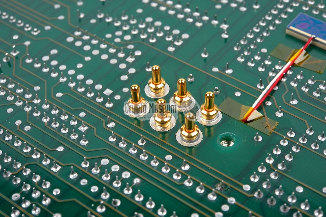
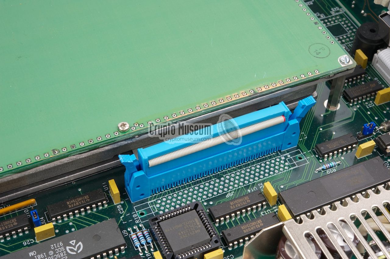
Inside the crypto unit are two large square PCBs
that are mounted together as a sandwich,
with the component sides of the PCBs facing each other.
The sandwich is mounted to the bottom shell by means of 8 bolts at the
edges of the upper PCB which is slightly larger.
It is shown in the image on the right, with the lower board up.
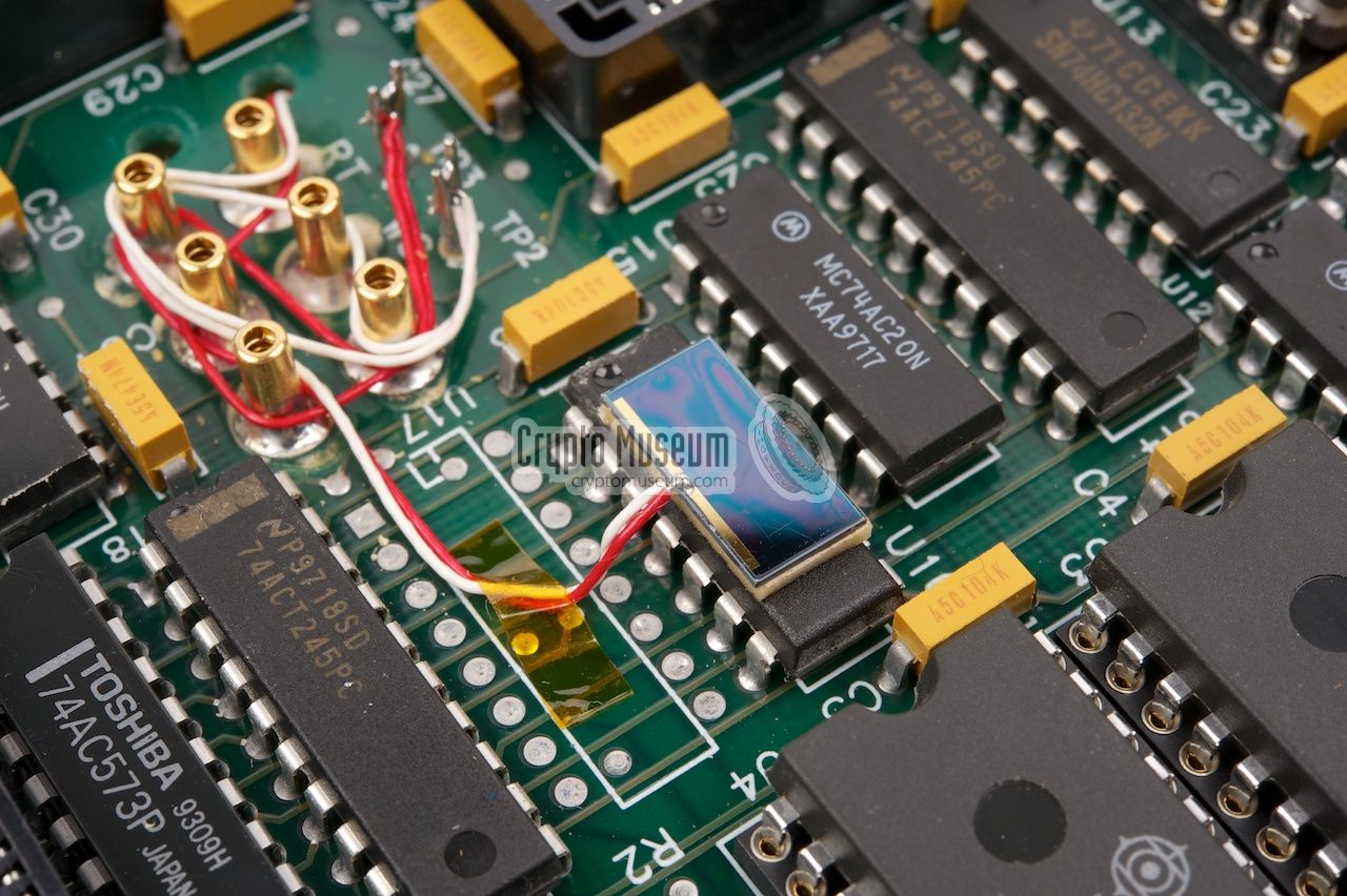
The next tamper protection is a light sensor
that is mounted at the center of the upper PCB,
close to the spring-loaded contacts.
It is connected to the PCB via red and white wires.
A similar light sensor
is present at the other side of the stack.
|
|
|
|
The light sensors
are the next stage in tamper protection.
As soon as any of the light sensors picks up the slightest trace of light
(visible or infra-red), it will trigger the tamper alarm and cause the
keys to be deleted. Cutting the wires to the light sensors will also
set off the alarm.
|
The two sandwiched boards can be separated
by removing four small bolts at the edges of the upper PCB and lifting
the lower board from the 96-pin DIN socket that connects the two boards.
The image on the right shows the upper board,
which is marked HOST 720. It contains the host processor, an Altera CPLD,
the firmware and a lot of 'glue logic'.
At the right, aside the 96-pin DIN connector, is the
AM9568, a dedicated Data Ciphering Processor made by AMD [2].
It supports DES and was at the time under strict export control
by the US Department of State.
|
|
|
|
The AM9568 allows a data throughput of 1.5MB/s (approx. 15Mb/s) with was
fast enough for real time encryption of high-speed serial lines and 10Mb
ethernet connections.
The Data Encryption Standard (DES)
was controlled by the US Bureau of Standards.
Today, DES is no longer considered secure for interbank financial
transactions
and has been superseded by Triple-DES and AES.
|
The HOST board connects to the main board via the
grey high-density ribbon cable
that is visible at the top left in the image above. In the top corner
is the 8.192 MHz crystal oscillator. At the center of the HOST board is
another light sensor,
that is glued on top of one of the existing chips.
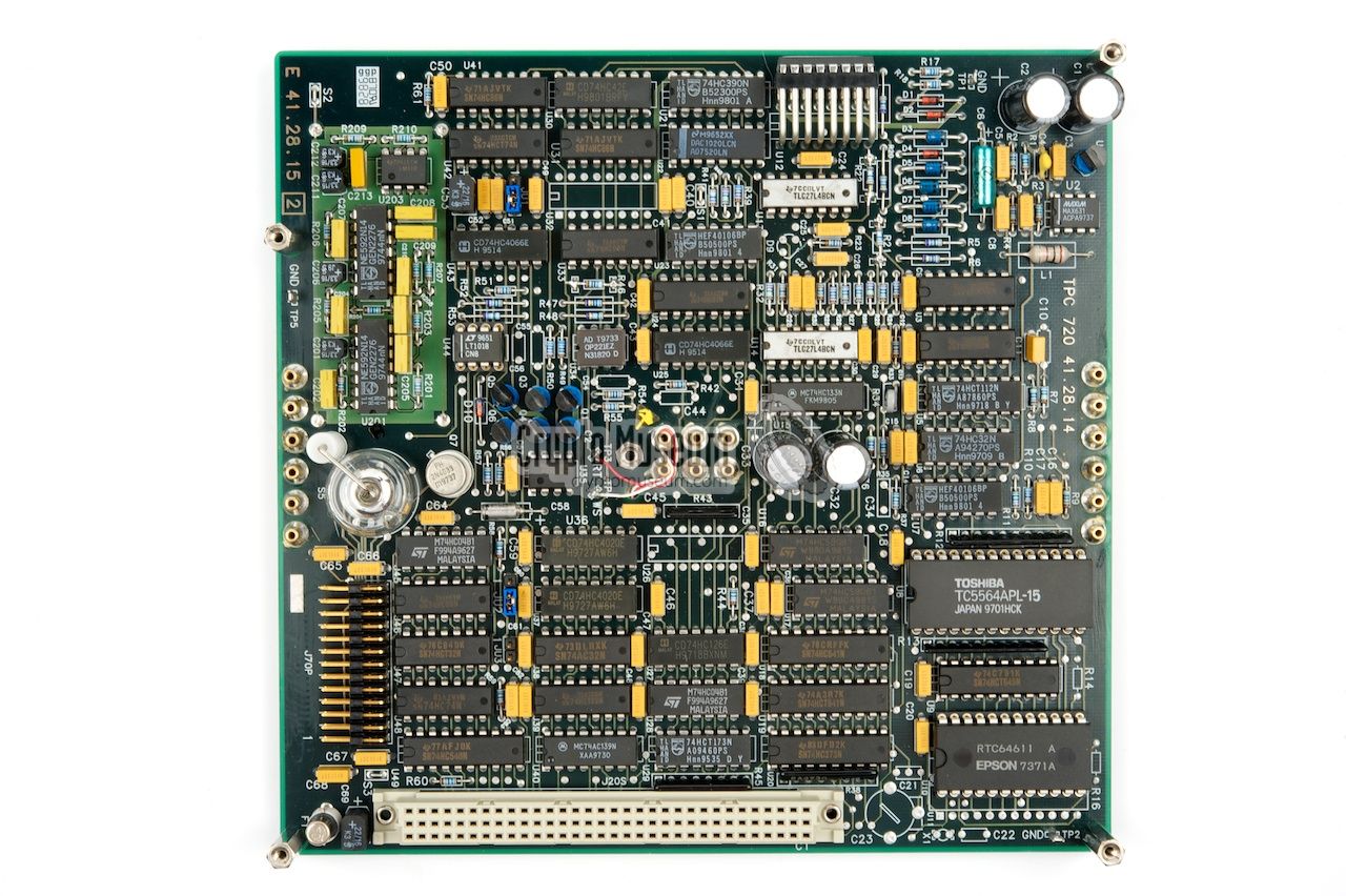
The bottom PCB
contains the other half of the crypto unit. It is connected
to the host board by means of a large 96-way DIN connector at the edge of the
PCB. This board holds the
Real-Time Clock (RTC), the battery-backed STATIC
RAM (for holding the key variables) and a
socketed PROM.
|
|
|
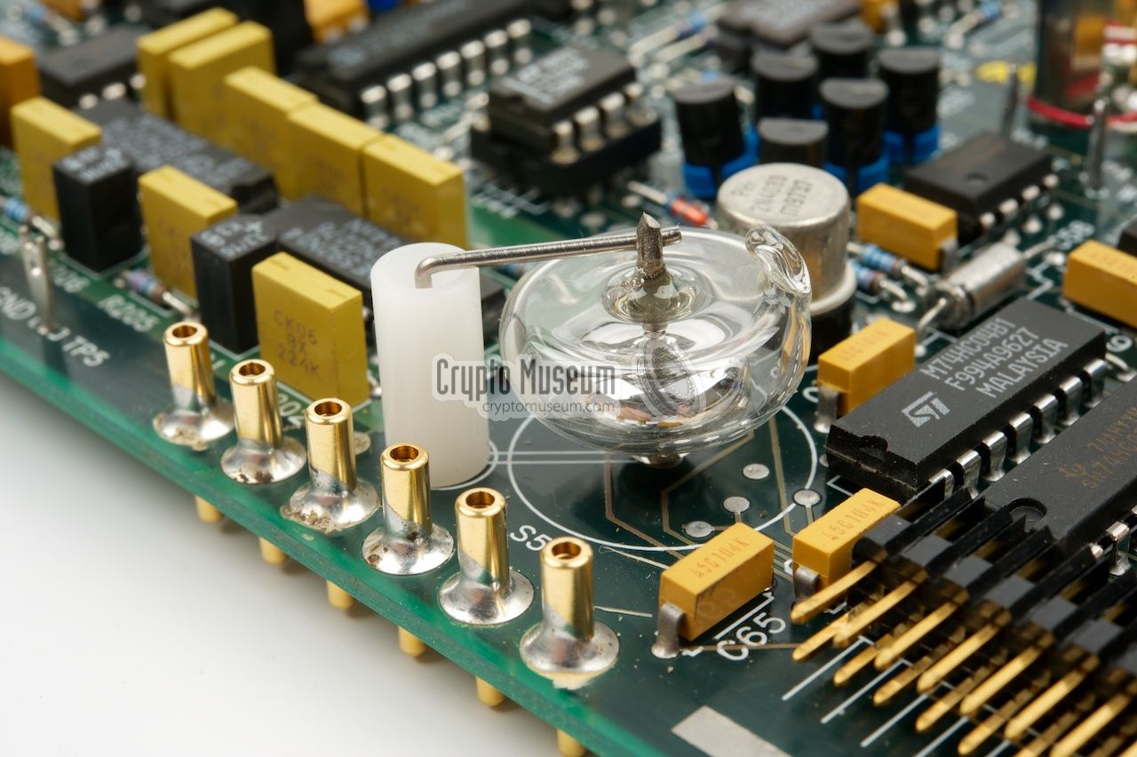
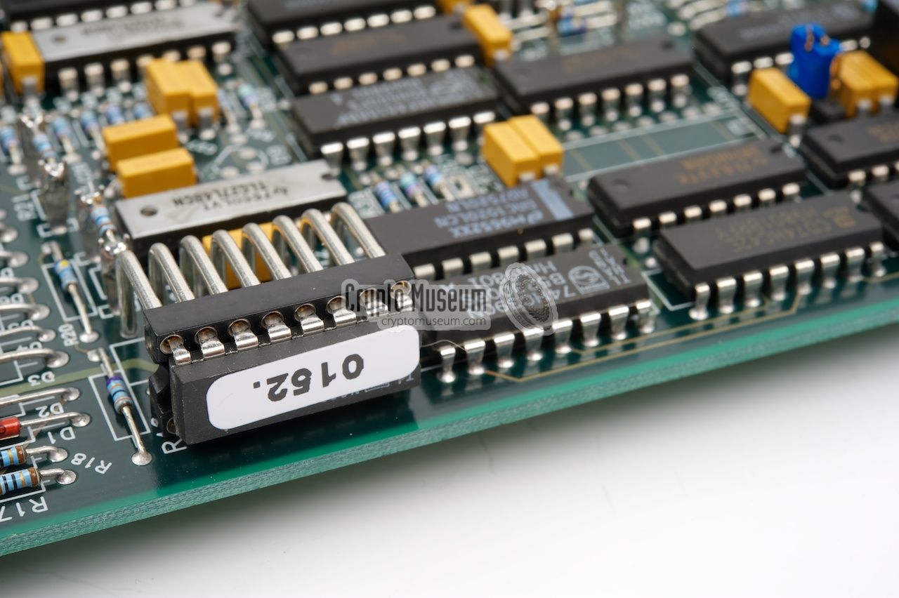
The bottom PCB also contains a true random noise generator, built around
two NE592 video amplifiers [3].
It was used for generating new truely random key
variables for each new SWIFT message. This board also holds the final
stage in tamper protection: a
mercury filled glass bulb,
which acts as a tilt sensor.
It is mounted close to the edge of the bottom PCB and
is shown in the image above. Tilting the device,
raised the tamper alarm and purges the crypto keys instantly.
The bottom shell
of the crypto unit is similar to the top shell. It also
contains meander tracks at the bottom and the sides, which are connected to
the bottom PCB by means of contact pads and spring-loaded contacts.
The crypto unit is so well protected that it is virtually impenetrable.
|
The Gretacoder 720 was part of the 700 family of
devices, that started life in the late 1980s or the early 1990s.
Based on many years of development of encryption devices for secure
payments for TELEKURS, the organization that controls
the transfer of money between Swiss banks, Gretag was asked to
develop similar products for EUROCHEQUE payments and for the
Italian Bancomat System. Many of these products were developed
in close cooperation with the customer [4].
The Gretacoder 715, for example,
was developed especially for TELEKURS and was used
for secure payment transactions between all major Swiss banks.
It is about the same size as the Gretacoder 720,
but has a slightly different front panel. Rather than the
EPROM slot (for the external key variable), it accepts a memory card.
It has a 2 x 16 character LCD display.
In 1989, the Italian Società Interbancaria per l'Automazione
(SIA), decided to add cryptographic security to its Bancomat System
that was used by all major banks in the country. The contract was
signed in October 1989. For this project, Gretag developed the
Gretacoder 700, a device that was very similar to the Gretacoder 720,
but with different communication ports.
A total of 1000 Gretacoder 700 units were ordered by the Italians,
which were installed in 500 banks (2 in each bank). By July 1991,
200 units had already be delivered to SIA and the rest was delivered in
the following months. At the time it was Gretag's most complex
software project [4].
To accomodate the wide variety of computer systems used by
the Italian banks, the Gretacoder 700 had four data ports, each with
four selectable data protocols. The later Gretacoder 720 — featured
here — is nearly identical, but has only three data ports:
two ports for RS232 or X.25 serial communication and one Ethernet port.
It is otherwise nearly identical.
|
|
|
|
Any links shown in red are currently unavailable.
If you like the information on this website, why not make a donation?
© Crypto Museum. Created: Wednesday 28 August 2013. Last changed: Friday, 30 May 2025 - 09:42 CET.
|
 |

|
|
|