|
|
|
|
|

|
|
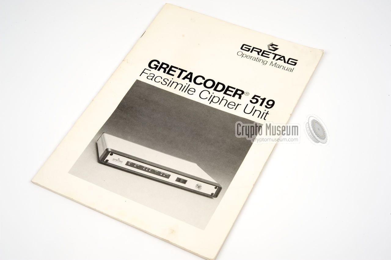
← Gretag Fax
Facsimile Cipher Unit
The Gretacoder 519, or GC-519, was a high-security fax encryption
device, developed and introduced in 1984 by Gretag in
Switzerland. It was intended for sending classified documents through a
fax machine over standard (analogue) telephone lines with speeds up
to 9600 baud.
|
The GC-519 was suitable for a limited range of approved fax machines
and required a special interface (and possibly additional firmware) for
each model that was available on the market at the time. For this reason the
user had to quote the model number when ordering a GC-519.
Generally speaking, the GC-519 was connected between the (analogue) modem
and the actual fax machine via a V.24 interface (RS-232). In some cases
it was possible to use the internal modem of an existing machine, if
the connection to the internal modem could be isolated.
|
|
|
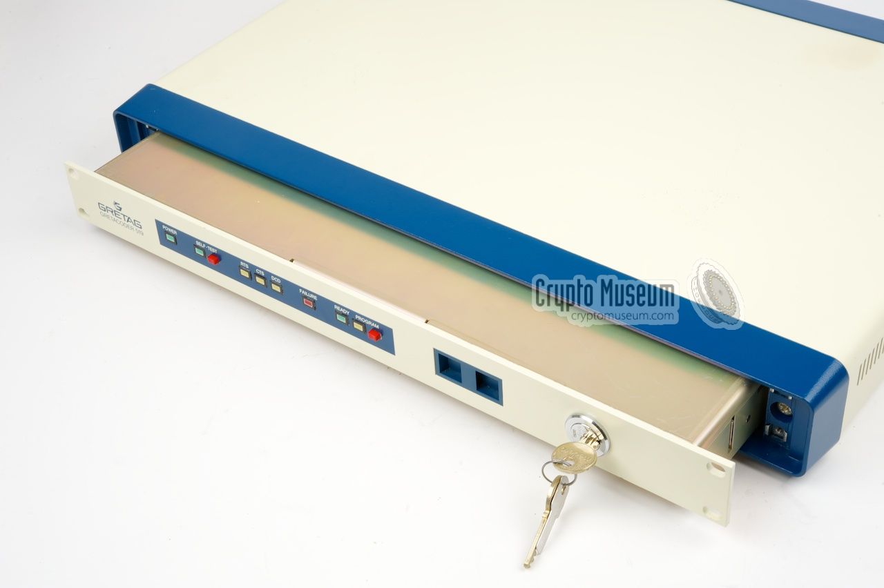
The GC-519 was available in two case variants: as a 19" rackmount unit,
or as a desktop unit. In the latter case, the 19" rackmount unit was
built inside a heavy metal enclosure that could be placed under the actual
fax machine. In order to protect the unit against tampering, it is locked
inside the enclosure with a physical key.
Without this physical key the case can not be opened.
Furthermore, the GC-519 was available in two software variants: a Closed
User Group version (CUG) and an Open User Group configuration (OUG).
in the former case, all users share the same set of cryptographic keys,
whilst in the latter case separate keys were used for each user pair.
|
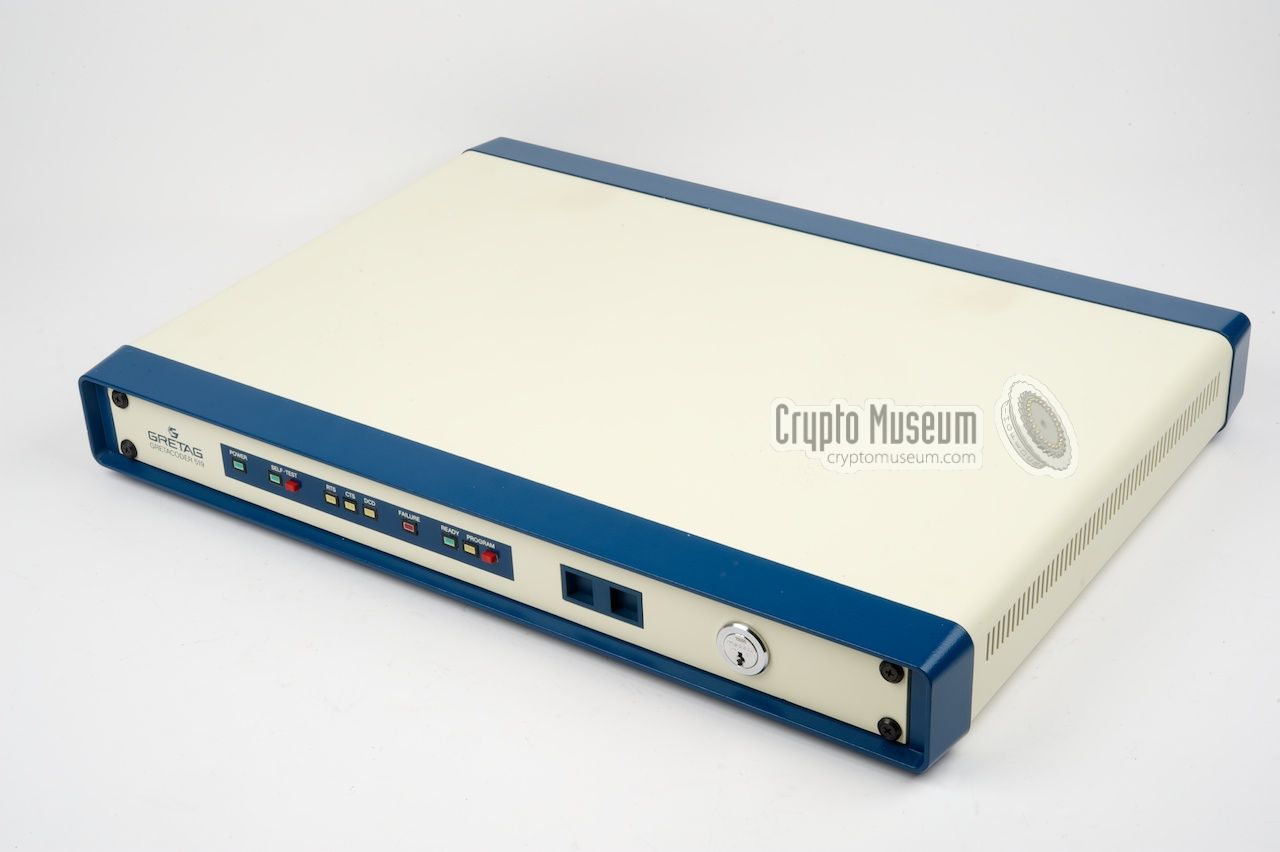
In everyday use, controlling the GC-519 is pretty straightforward.
All connections are at the rear and all controls are at the front.
The image below shows the front panel of the unit. Most of the front
panel is taken by the 10 LED indicators that show the current state
of the machine.
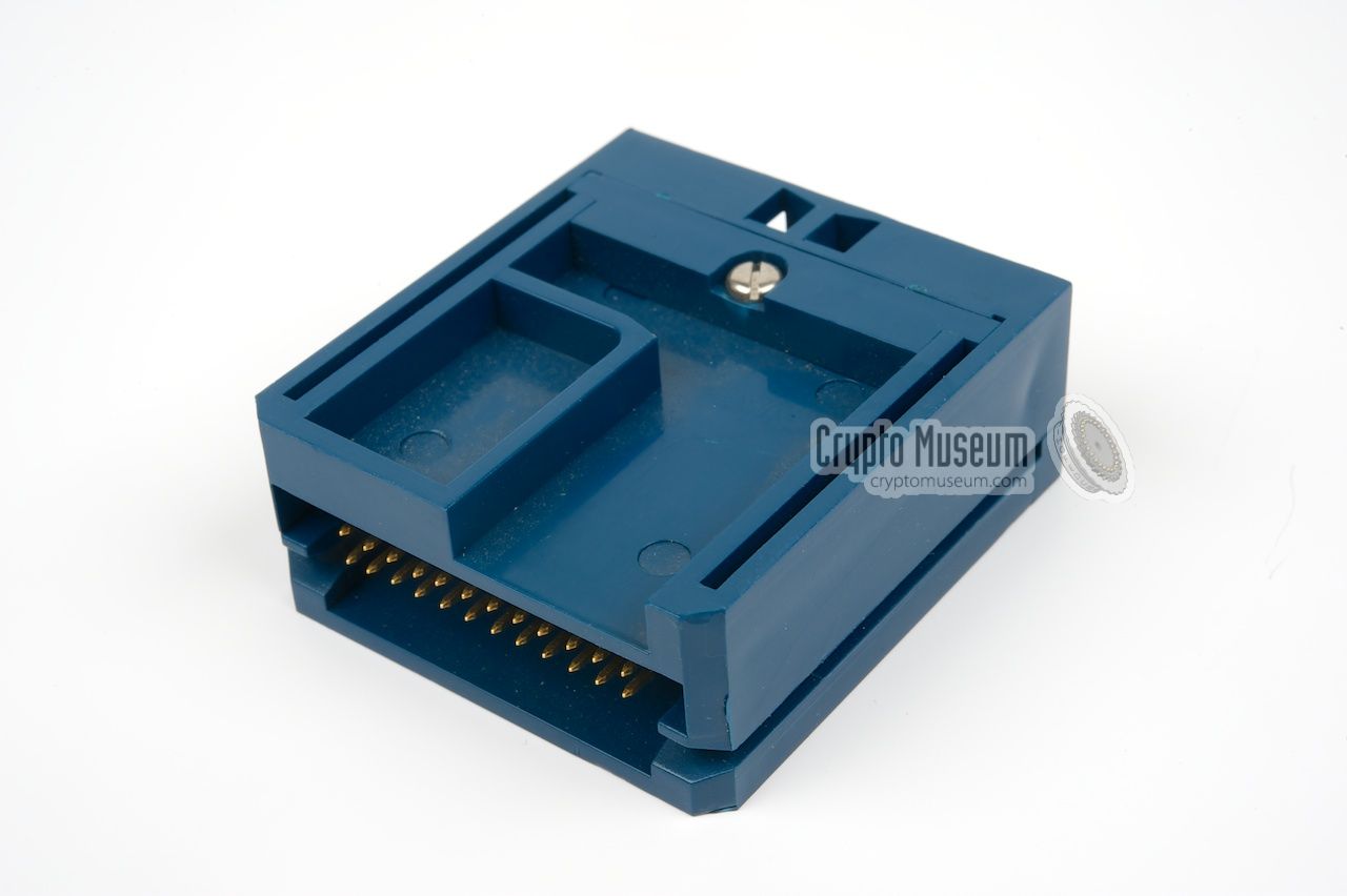
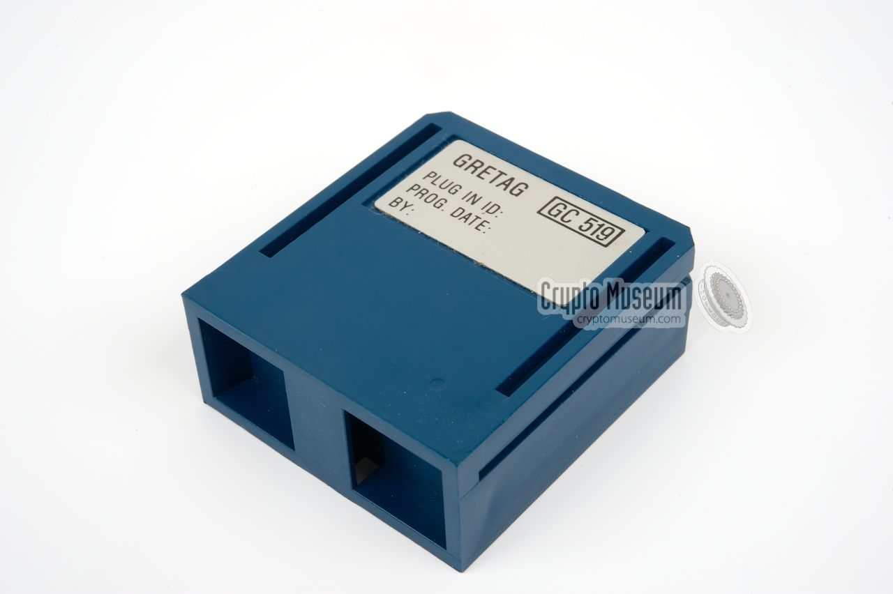
To the right of the indicators is a blue Key Module.
It contains an EEPROM with the personal keys and key pairs.
At the far right is a physical lock
that prevents unauthorised removal of the key module. It also protects
the case against unauthorised opening. All connections are at the rear:
At the far right is the mains socket with a selector for the correct mains
voltage. At the left are three D-type sockets. The one at the left is for
the connection to the fax machine, whilst the rightmost one is connected
to the modem. At the centre is a 15-way D-type socket to which the
remote control unit (RCU) is connected. A label indicates which type of
interface is present.
|
The unit has no power switch. Once it is connected to the mains, it is
operational and ready to receive fax messages. Depending on the software
version (CUG or OUG, see above), two different remote control
unit were available.
For Closed User Groups (CUG) a simple remote control unit (RCU) with
4 push-buttons and a mechanical key was used. As all partners share the
same crypto key, there is no need to select a suitable key in this
configuration. For Open User Groups (OUG) however, the more advanced RCU
with LCD display, shown on the right, was used.
|
|
|
The RCU was connected to the 15-way D-type socket at the rear of the unit.
It was used for entering a password (in case a password had been configured)
and selecting the appropriate key for the remote station. Each key is
identified by a 4-digit number and is stored in an EEPROM inside the
blue Key Module that is
inserted at the front of the GC-519.
It has room for 56 keys.
The actual keys can be generated automatically by the GC-519, but
they can also be created manually and entered via the keypad.
In that case, each key consists of 40 decimal digits that are entered
as 5 groups of 8 digits each. Each group is followed by a 2-digit checksum
in order to avoid typing mistakes. The manual describes in detail how to
calculate the checksum [1].
|
|
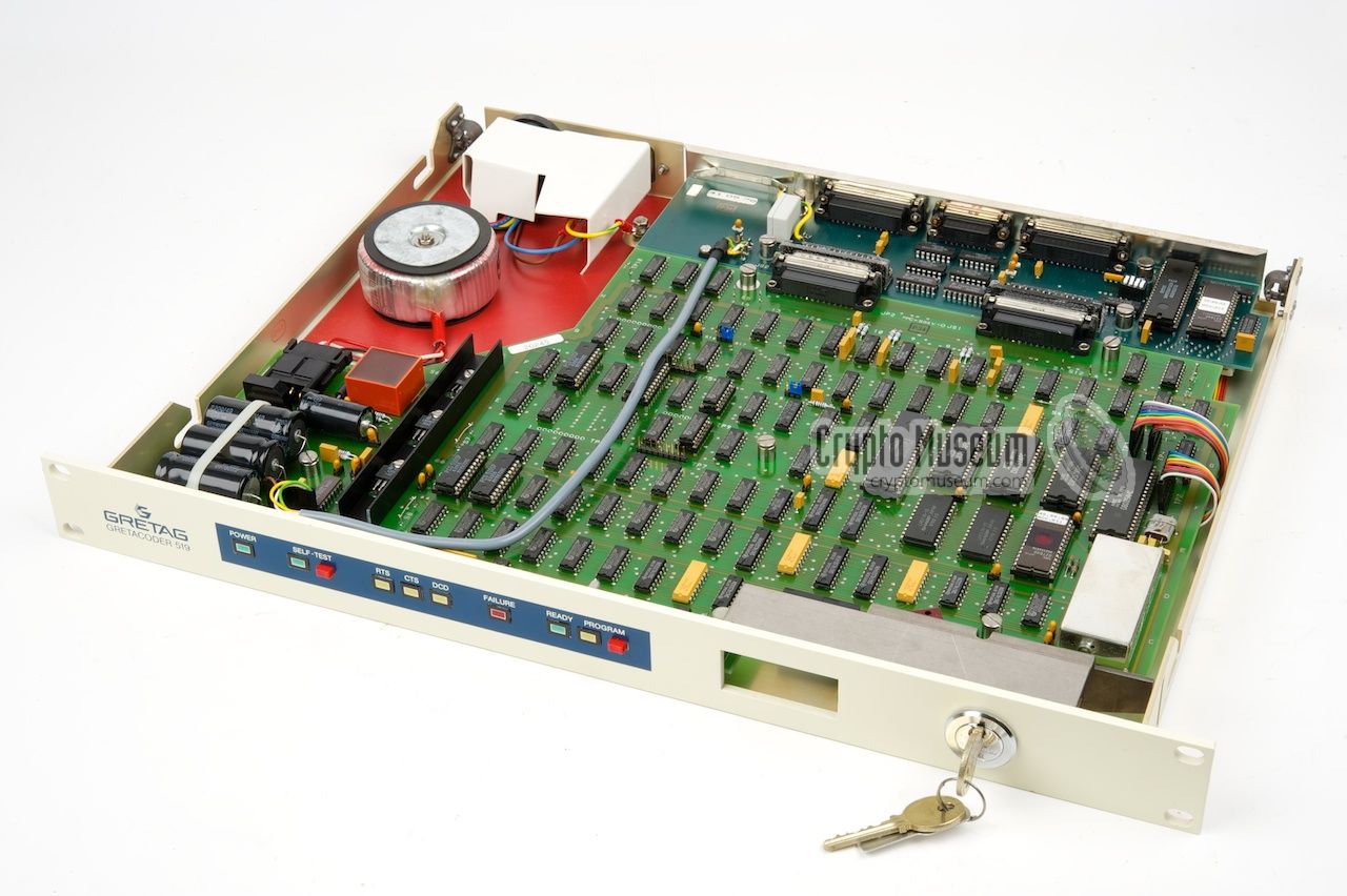
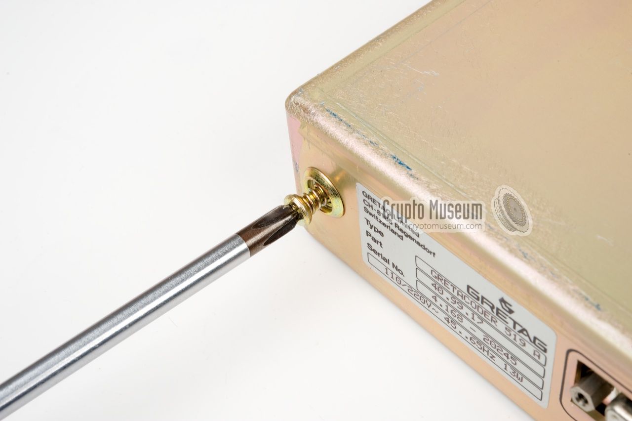
The GC-519 is a very robust rather large unit that is housed inside a
1U 19" rackmount cabinet. In order to get access to the interior of the
machine, the physical key has to be
turned fully counter clockwise.
If the unit is mounted inside the 1U desktop case, the four black cross-head
bolts at the front can now be removed and the actual unit can be
pulled out from the front.
|
The case of the actual device itself can be opened by
loosening the two spring-loaded bolts
at the outer edges of the rear panel. Slide the top
panel toward the rear and lift it off. Again, the
top panel can only be removed
if the physical lock is turned fully counter clockwise.
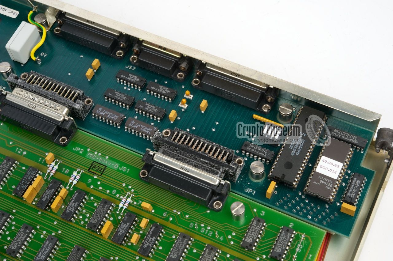
The interior is pretty straightforward and well organised. Most of the
space is taken by the main board which is the actual encryptor. At the rear
is a narrow board with the V.24 interface
to the modem and the fax machine.
At the left (in the read area) is the mains transformer.
|
|
|
|
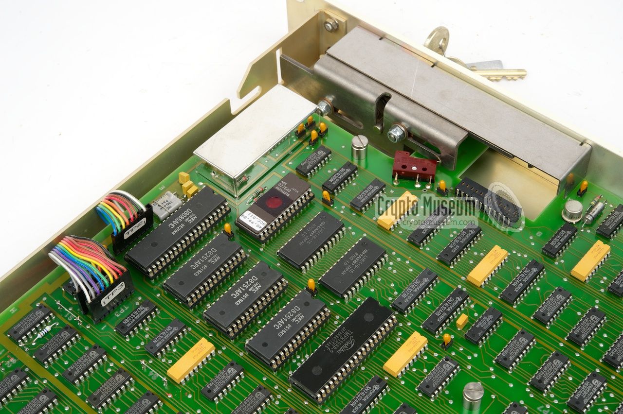
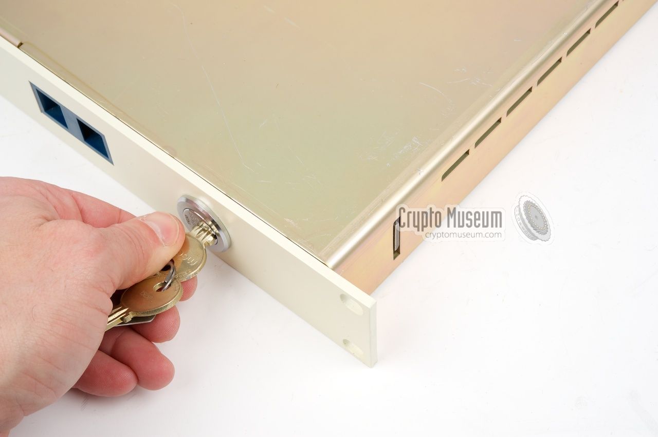
At the front panel of the GC-519 is a
physical lock that prevents the case
from being opened by an unauthorised person. It also locks the
blue key module in place. In order to remove the key module or open the case,
the physical key has to be rotated
fully counter-clockwise.
|
In locked state, a heavy metal bar is
extended at the right side of the case.
When built inside a 19" rack, or inside the 1U desktop unit shown here, this
bar prevents the GC-519 from being
removed from the enclosure.
A very effective way of slowing down a tampering attempt.
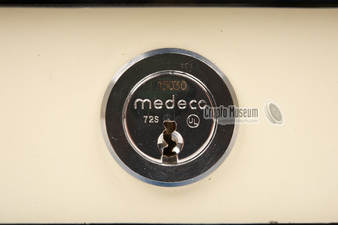
As an extra safety measure, a MEDECO security lock is used. Unlike a common
cylinder lock, this variant has tumbler pins which may be tilted sideways by
the key, depending on the
shape of the individual cuts of the key.
This makes lockpicking more difficult and time consuming.
|
|
|
|
This is called a bi-axial lock and for a long time, MEDECO advertised it
as one of the safest locks on the market.
And even if the lock was successfully picked, a
built-in tamper switch
ensured that the internal cryptographic keys were destroyed immediately
when the lock was turned.
|
|
|
|
Any links shown in red are currently unavailable.
If you like the information on this website, why not make a donation?
© Crypto Museum. Last changed: Saturday, 24 February 2018 - 07:29 CET.
|
 |

|
|
|