|
|
|
|
|

|
|
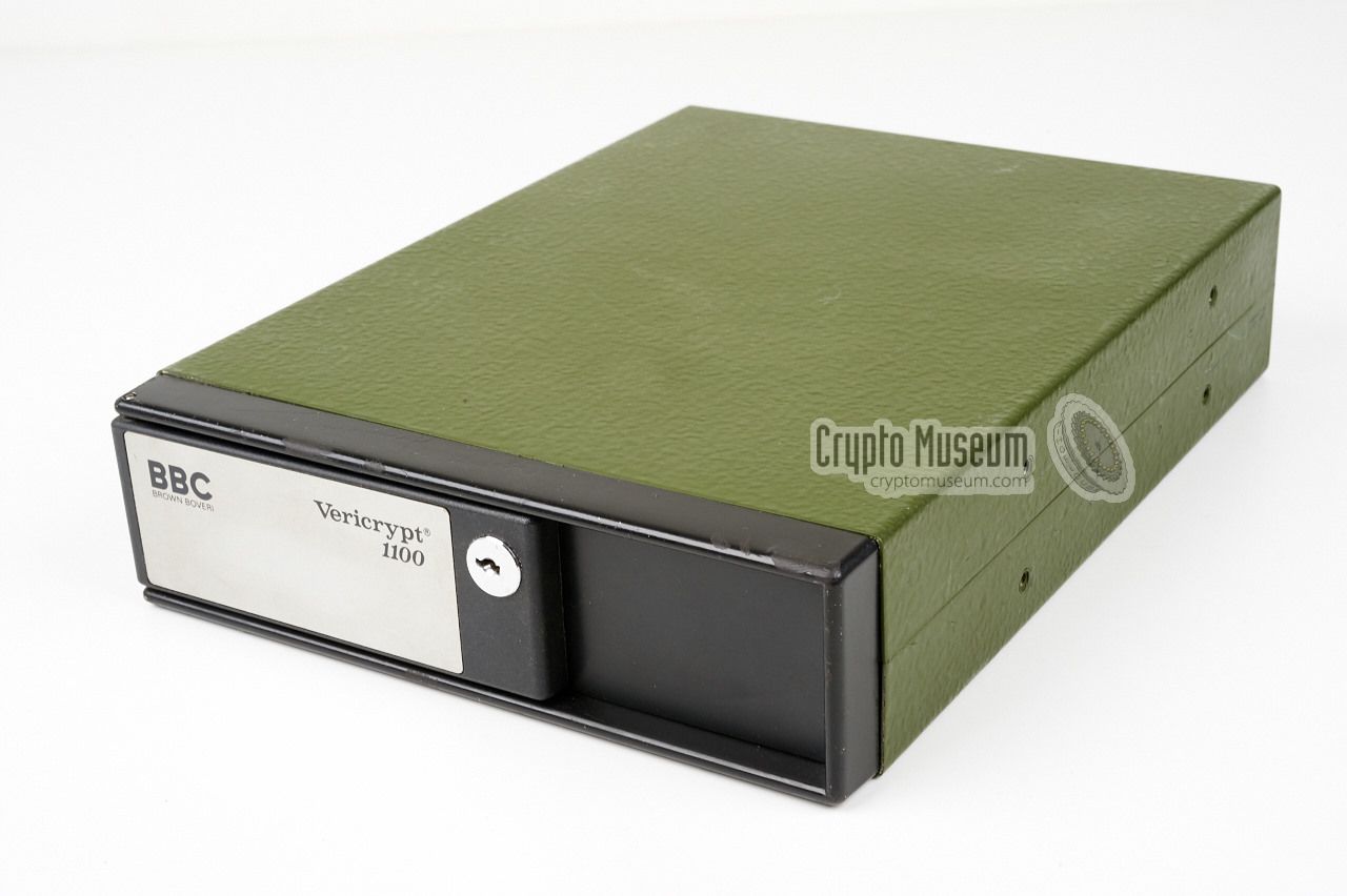
BBC ← Cryptophon
Time-division speech scrambler SV12
Vericrypt 1100 was a
time-domain speech scrambling device,
developed around 1980 by
Brown Boveri and Company (BBC)
in Switzerland
as the successor to the Cryptophon 1100
with which it was compatible [3].
It was intended for use with narrow band VHF/UHF 2-way radios
and was widely used by Police Forces in Europe in the days before digital
encryption became mainstream. It is also known as SV12-1101
and by its military designator NSN 5810-12-188-5670.
|
The Vericrypt 1100 series can be seen as the miniaturised version of
the Cryptophon 1100
series, that was released six years earlier.
Unlike the Cryptophon, where the daily key was set by means of six
thumbwheels hidden behind a flap, the encryption keys of the Vericrypt
had to be entered by means of an external
key loader.
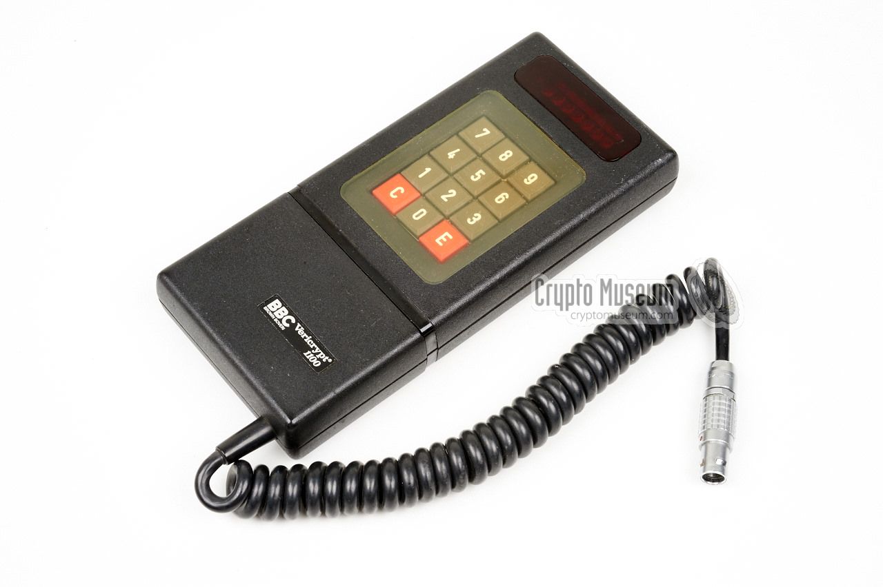
The image on the right shows a typical Vericypt 1100 unit [1] with the
proprietary Vericrypt key loader [2] connected to the LEMO socket at the
front panel. The keypad on the key loader is used to enter the 6
digits of the crypto key.
|
|
|
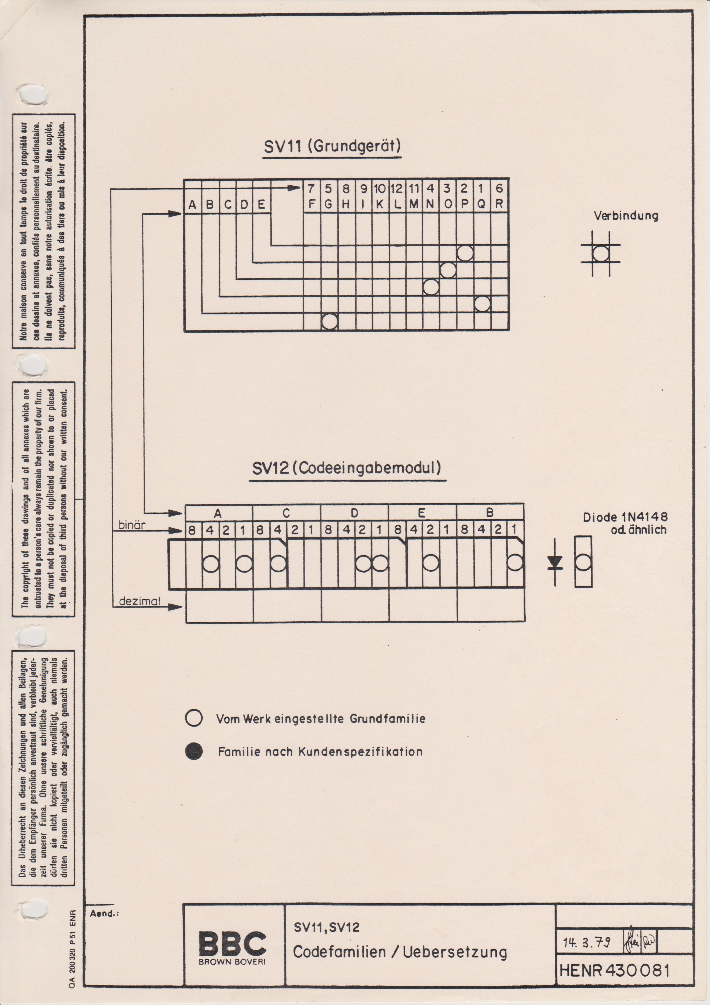
Once the key is entered, it is stored inside a Static RAM chip
and retained by a small lithium battery so that it does not get
lost when power is cut-off. Like the Cryptophon, the Vericrypt
also has an internal or basic key, which is fixed in a PROM.
Is is currently unknown how it is changed.
|
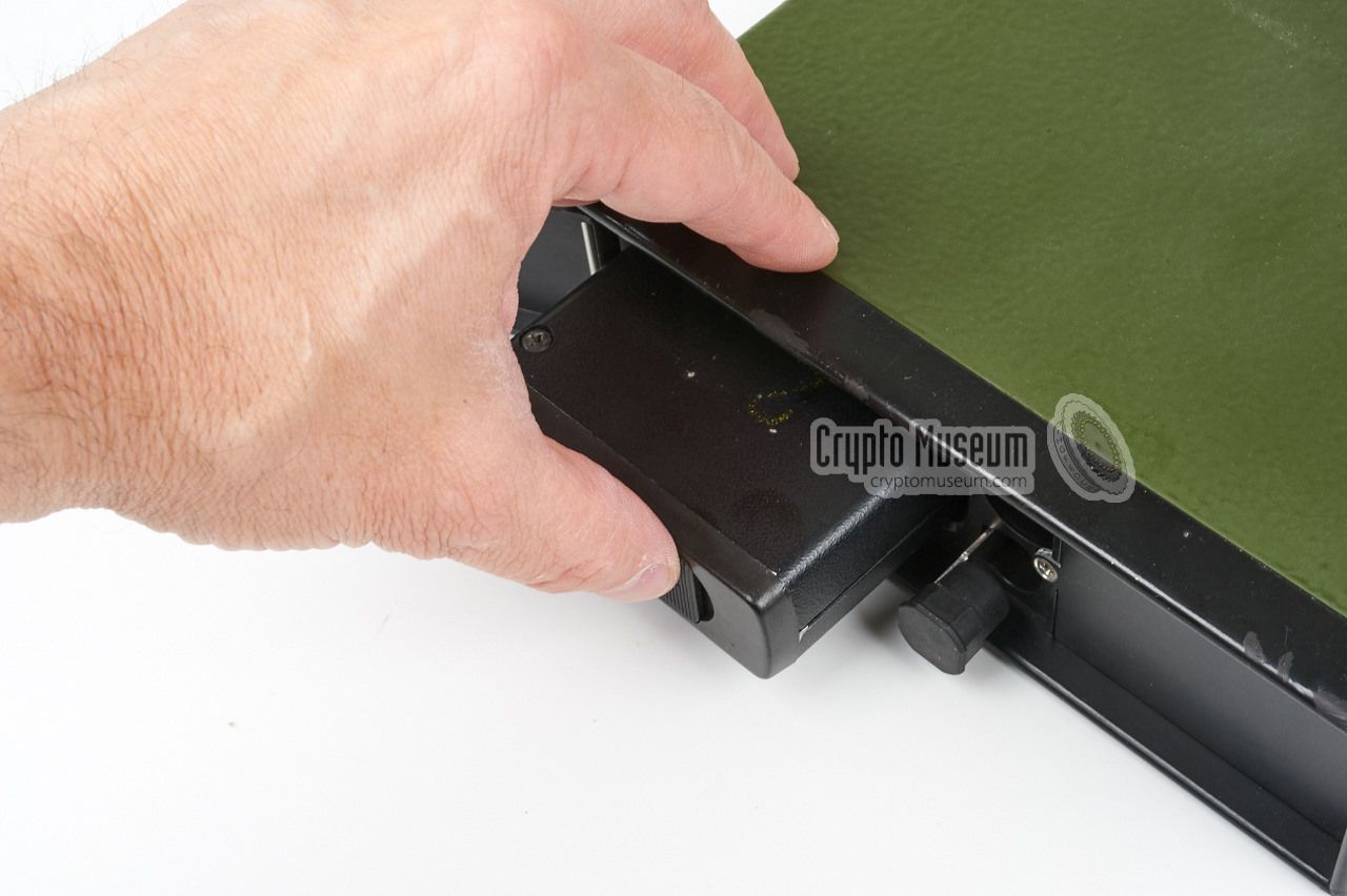
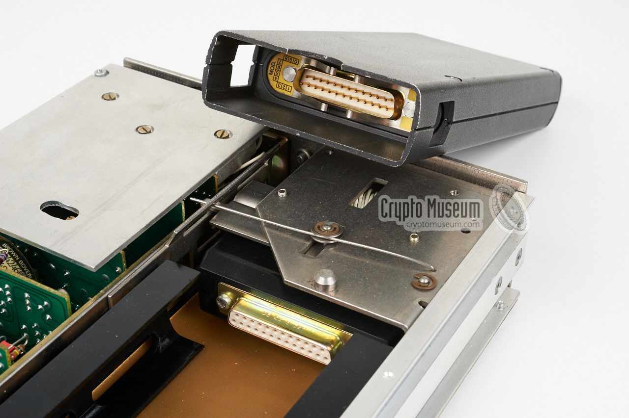
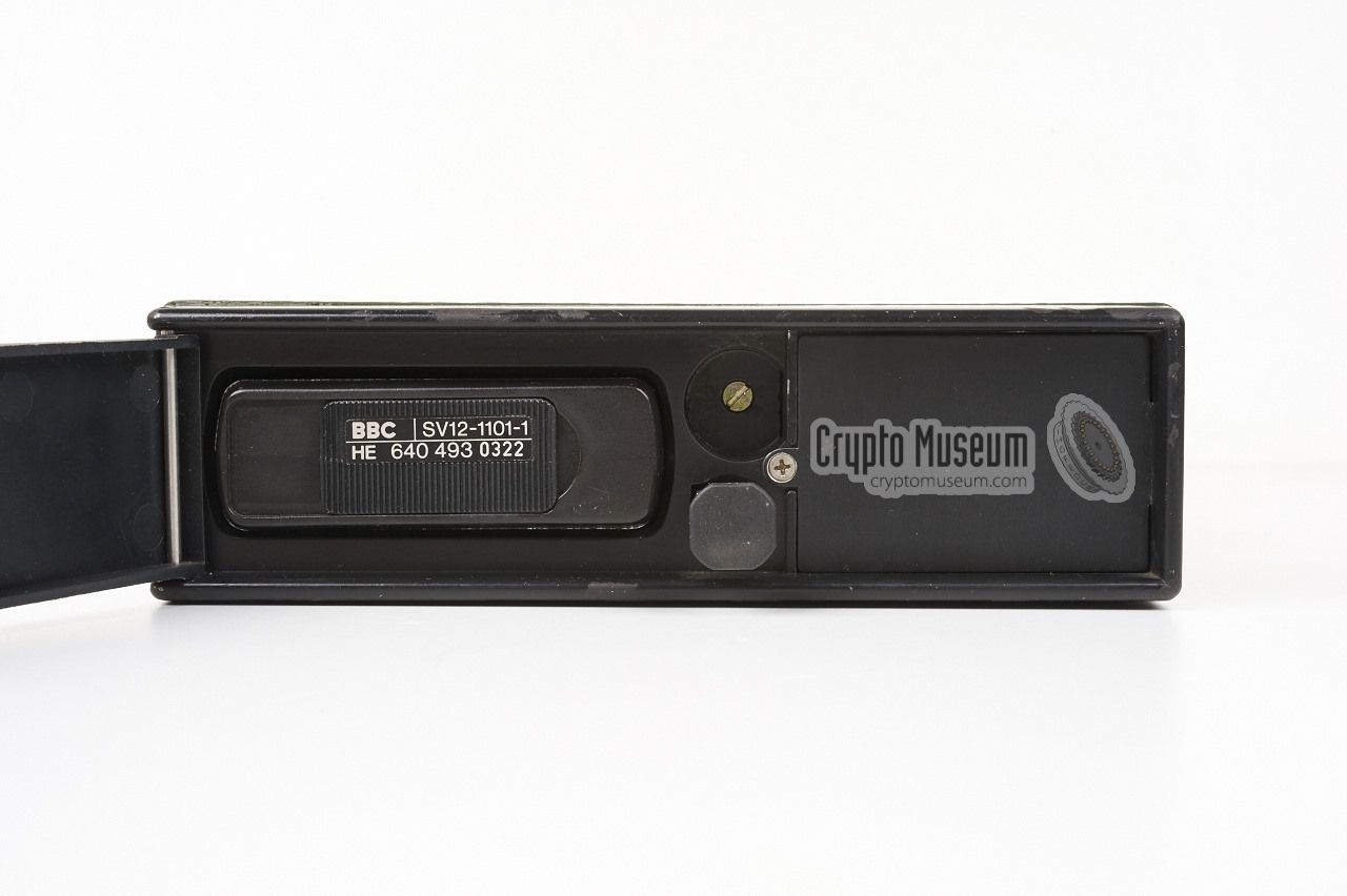
Although the Vericrypt unit above has nearly the same dimemensions
as the older Cryptophon, the actual crypto module itself is much
smaller. At the heart of the device,
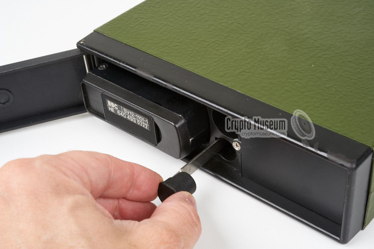
behind the lockable door, is
a removable unit
that has the same size and shape of an average
portable police radio.
It can be removed by pulling-out a knob
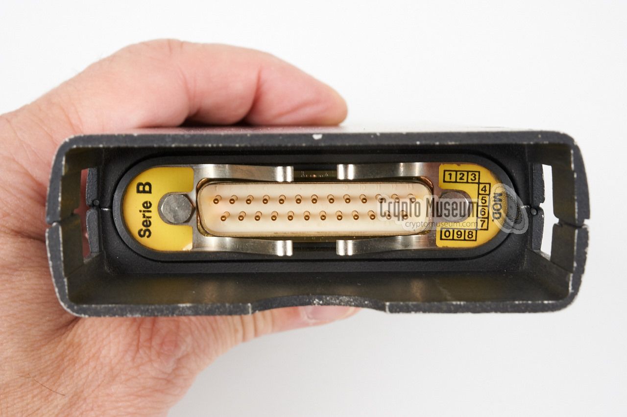
to the right of the door. At the rear of the crypto heart is a
25-way male plug that mates with a
female socket inside the unit.
The image on the right shows how the crypto unit is installed again.
The door should be locked to keep it in place.
|
|
|
The configuration shown above was used for mobile applications,
such as in a police car or a military vehicle. As the unit shown
here is green, it was probably used by the Army or the Border
Patrol. The green case merely acts as a carrier for the actual
1101 crypto unit. It houses quite a bit of additional electronics
though, which allows it to be connected to a telephone line as well.
|
There was another version of the carrier that had a socket for
the connection of a handset, to the right of the lockable door,
together with a switch and an indicator light. That version was
used for legacy installations in existing (police) cars.
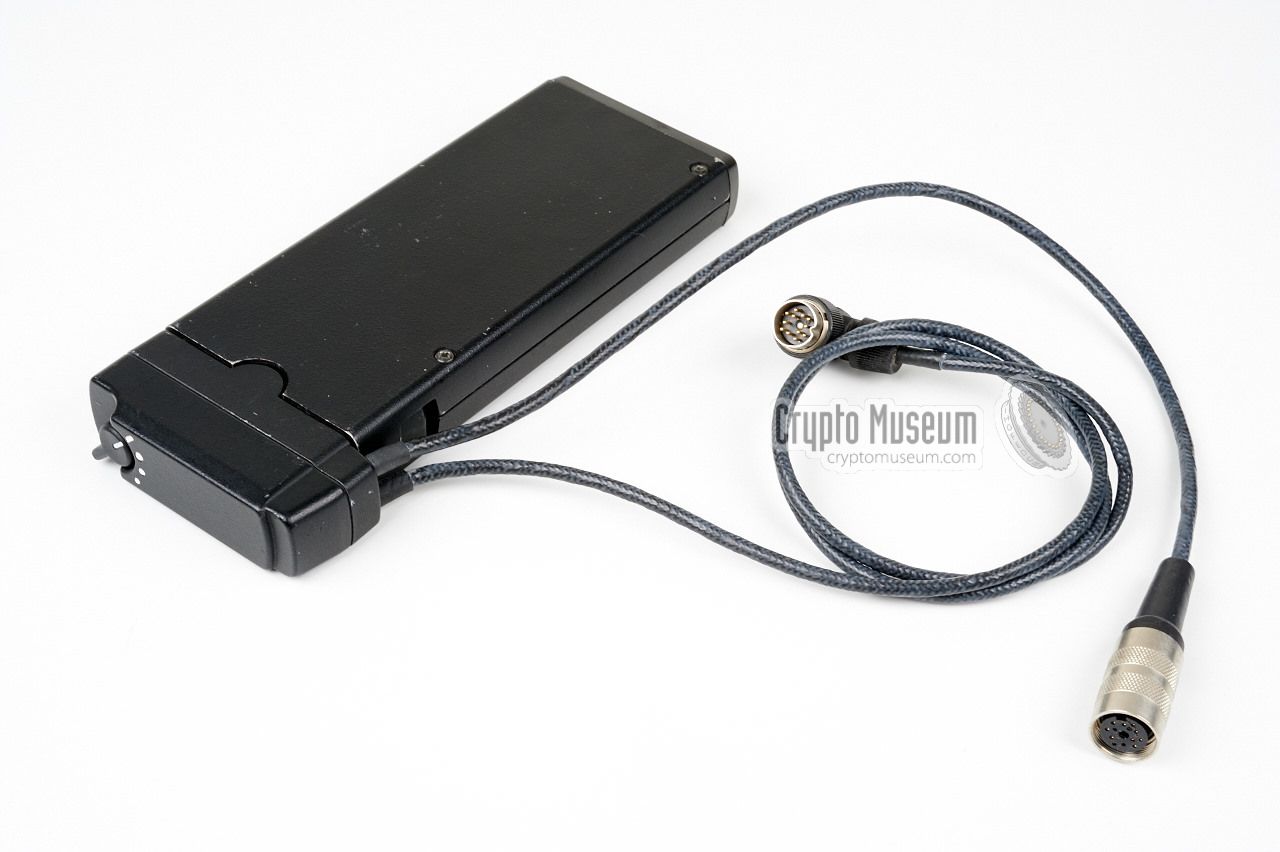
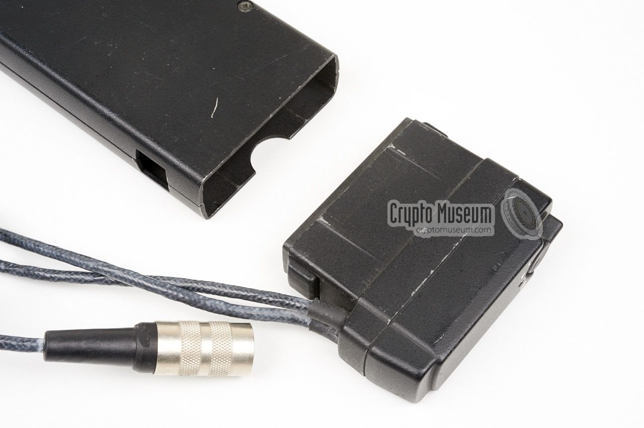
Unlike the older Cryptophon,
the Vericrypt was suitable for portable
applications as well. By adding a
small adapter to the
bare crypto unit,
the device was converted to a
portable unit,
that was roughly the same size as a conventional handheld radio.
The image on the right shows the unit with the portable adapter
installed.
|
|
|
The portable adapter has a small rotary selector on its
front panel, probably for the selection of the key, plus two leads
with connectors at the end: a short one and a longer one.
The female connector was for connection of the handset, whilst the
male connected mated with the handset socket of the radio.
In other words: the unit was inserted between the handset
and the radio.
When using the Vericrypt, the user has to be aware of a 0.5 second
delay in the audio path. This is a feature of the
time-domain scrambling that is used here.
The Vericrypt 1100 could also be used
on telephone networks, although it does not have
echo cancellation on 2-wire networks [2].
The unit shown here was used for many years by a crime unit
of the Dutch police, who used it in a number of high-profile cases.
Note however, that this type of encryption is inherently unsafe.
|
Apart from the mobile carrier shown above,
Ascom/Teletron provided various
other solutions for using a Vericrypt 1100 unit inside a vehicle.
The image on the right shows a so-called VIFA device that was designed
to hold one or two Vericrypt units. It is shown here with a single unit
installed in the leftmost bay (marked V1).
At the rear are the usual 12-pin DIN sockets
for connection to the radio, plus a female 37-pin sub-D socket for peripheral
equipment.
|
|
|
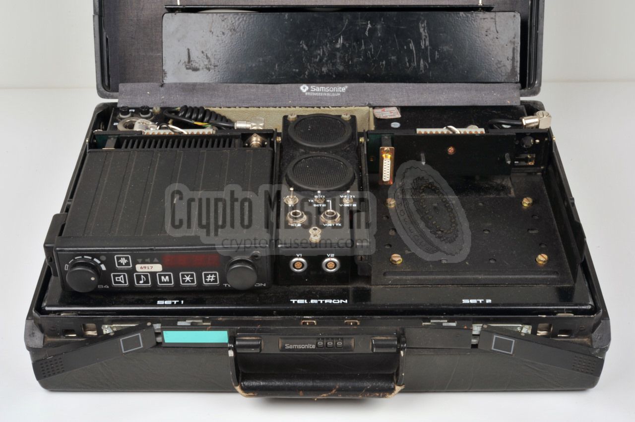
For temporary installations, such as in the unmarked vehicles of special police
intervention teams, the entire radio set with Vericrypt unit was often built
inside a customised briefcase, such as the one shown in the image on the right.
The cases were supplied by Ascom/Teletron
and contain a carrier frame that can
hold two radios and two Vericrypt 1100 modules. At the centre is the interface
for the microphones, speakers and the key loader.
The vericrypt units are located in the lower part.
|
|
|
The Vericrypt 1100 was also supplied by BBC as an OEM product to other
manufacturers. One example is the
Bosch FuG-8 (KF-802)
two-way VHF radio shown in the image on the right.
In the example, the bare Vericrypt unit is built inside an extra compartment
at the bottom of the FuG-8 radio. It is connected to the wiring of the radio
via the 25-way sub-D connector at one of the short sides.
➤ More information
|
|
|
Between 1978 and 1981, the Cryptophon 1100
and Vericrypt 1100 were tested
by a number of West-German agencies, such as the police, the Ministry of
Internal Affairs and the
German Intelligence Agency (BND).
They considered the system safe and between 1981 and 1982, a large number
of Cryptophon and Vericrypt 1100 units were installed with the various agencies.
In 1983 the East-German cipher bureau managed to break the cipher by
reconstructing the keys from a series of intercepts.
They also built their own equivalent of the Cryptophon, known as the
A-003, that was used in the breaks.
Another device, the so-called A-004,
was used to decipher the Vericrypt 1100.
As a result, they managed to read about 90% of the West-German Cryptophon
1100 and Vericrypt 1100-based radio traffic
during the 2nd quarter of 1988 [4].
|
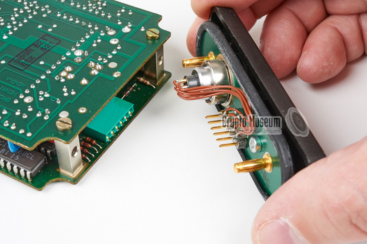
The interior consists of two printed circuit boards (PCBs)
that are mounted together as a
sandwich.
One PCB, the digital board,
acts as the carrier to which the rear panel (i.e. the
25-way male sub-D connector) is fitted. The other board contains
the analogue electronics.
The boards are connected together by
means of a long row of pins
along one of the long sides (blue strip).
The analogue board is held in place by four bolts at the corners.
After removing these bolts, the board can be taken out, as shown
in the image on the right.
It contains the main oscillator.
|
|
|
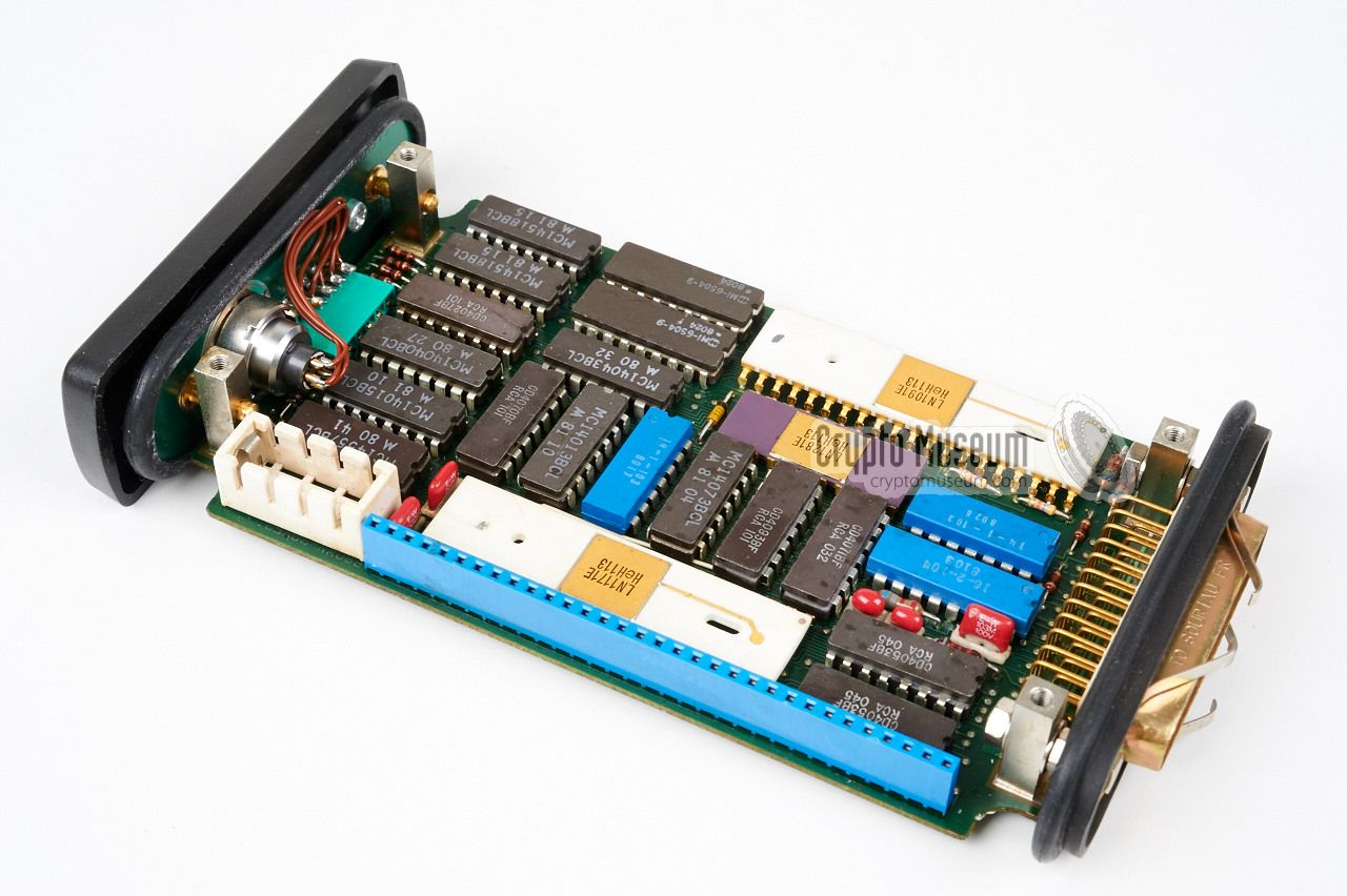
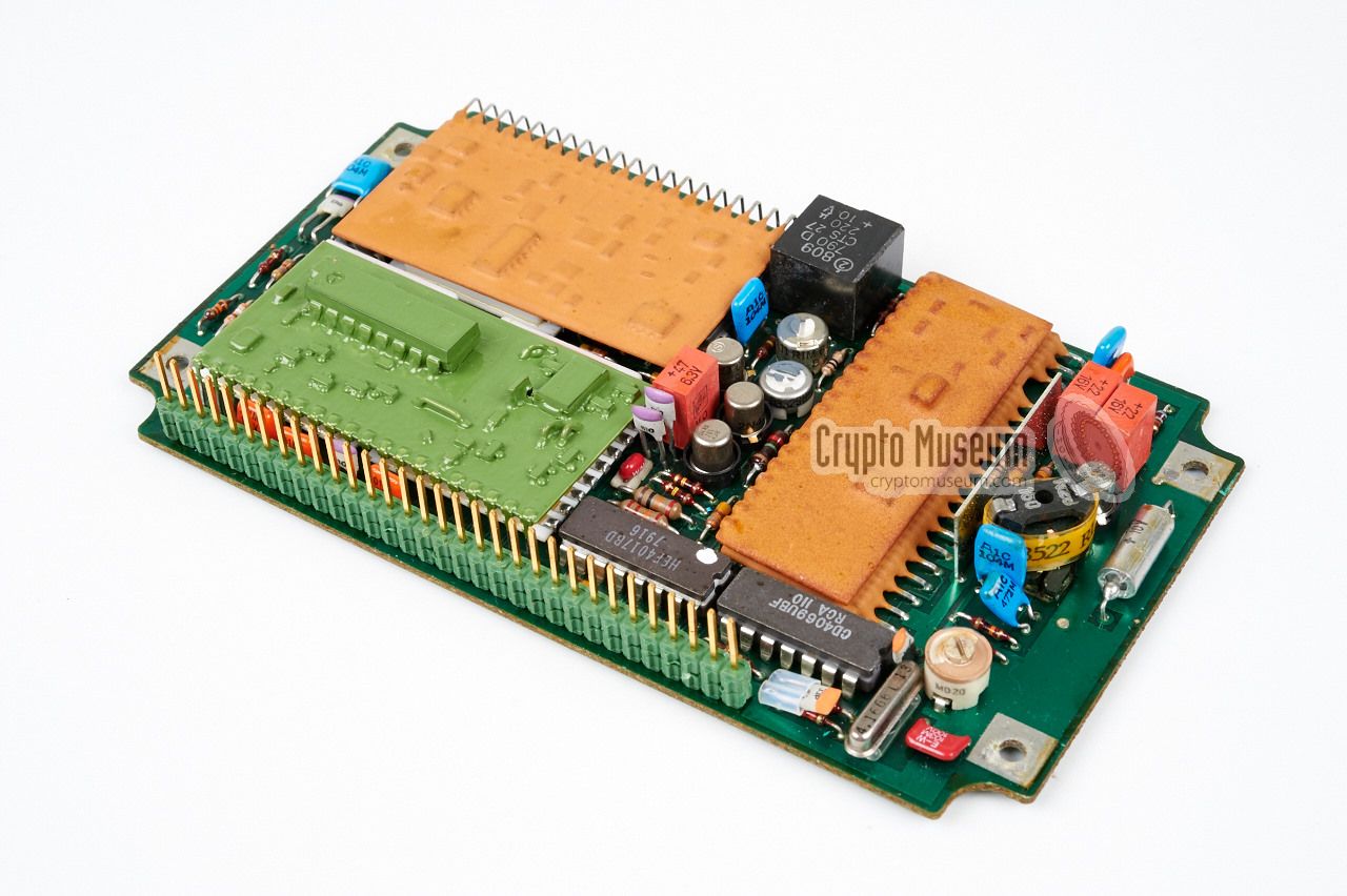
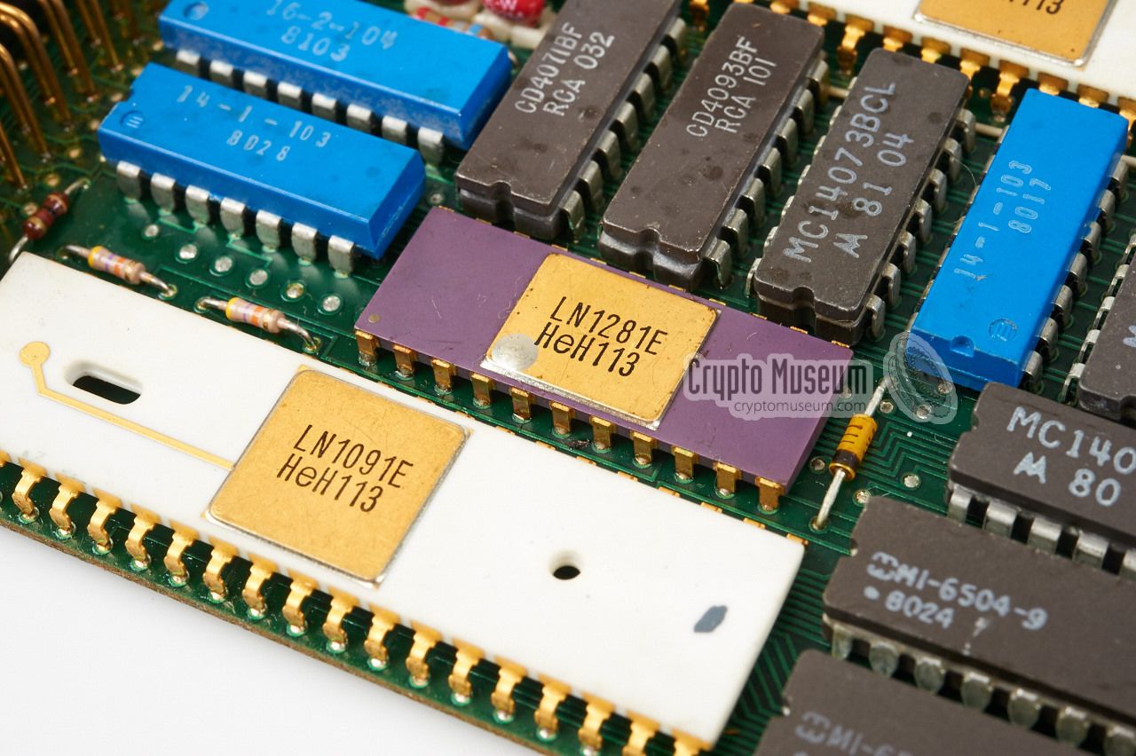
The digital board
is densely populated and hold a number of
components that are marked with OEM numbers. Nevertheless, we can
make a few 'educated guesses'. At the bottom left is the
main processor
(the white LN1091E) with a PROM or masked-ROM just
above it (LN1281E).
|
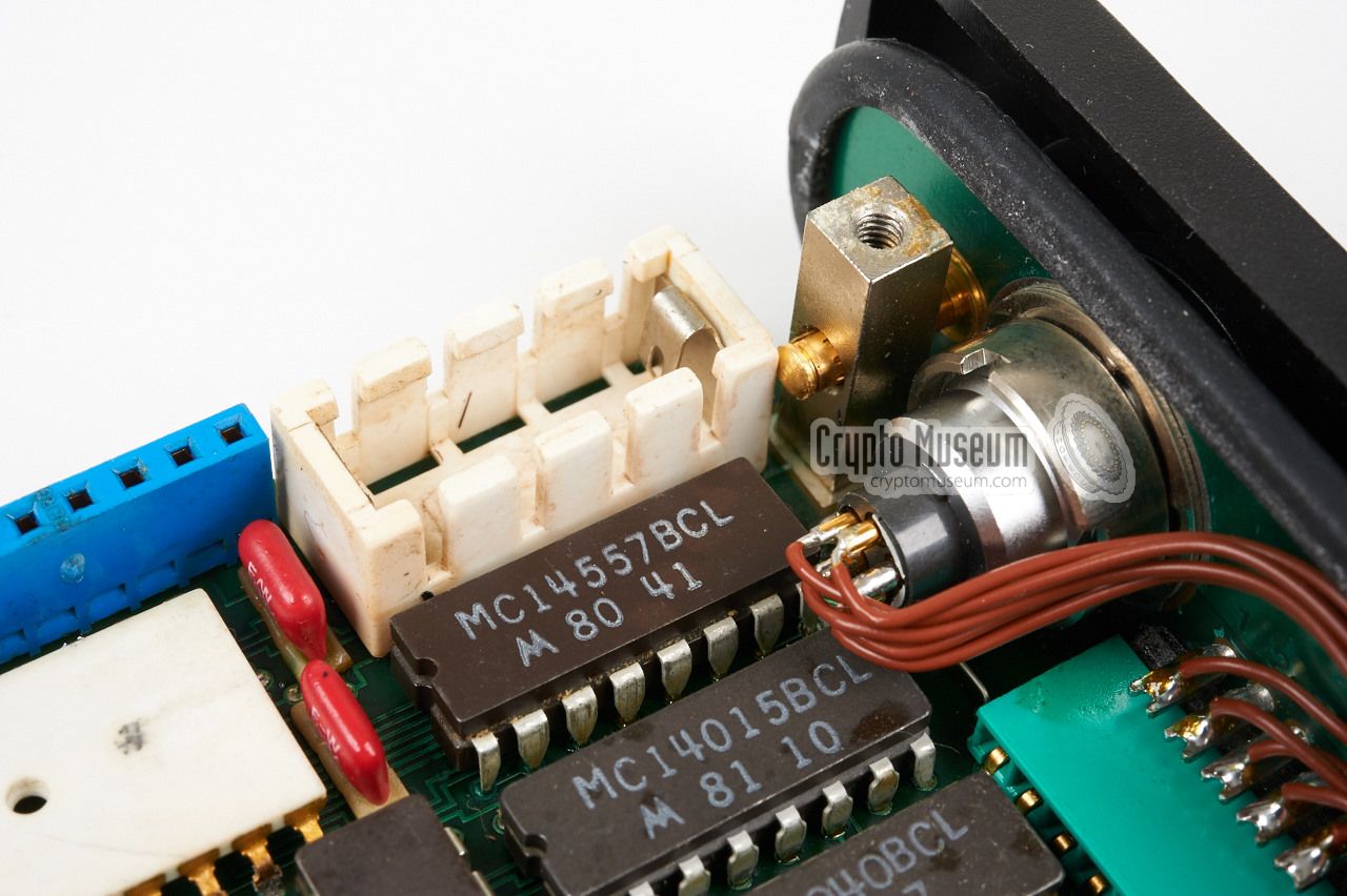
To the right of the processor are two Harris HM1-6504 CMOS RAM chips
that can hold 4096 bits each. These RAMs are used to hold the
6-digit cryptographic keys. They are retained by a small lithium
battery that is installed in a
fitting at the top right
(the battery is not installed here).
The big white chip marked LN1171 at the top edge of the board,
is an IO-expander. It forms the bridge to the analogue board.
The 25-way sub-D connector at the left is the bridge to the
outside world (i.e. the carrier). At the right is the front panel
that is fitted onto a 6-pin connector.
|
|
|
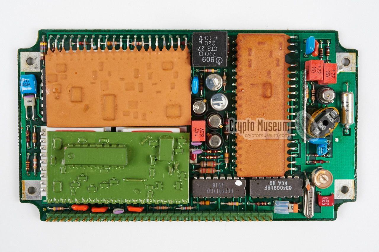
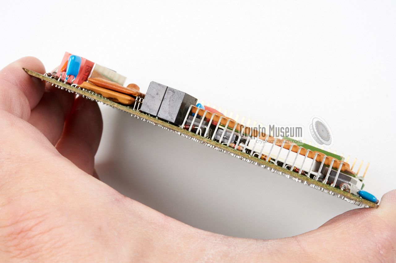
The analogue board
is clearly the more complex one. It consists
of various layers of components that are cleverly mounted on
top of each other in order to save space. It contains the same
analogue electronics as its predecessor, the
Cryptophon 1100,
albeit in a much smaller space.
|
Looking at the board from one of its sides
shows us that there are
three layers of components. All conventional components
(resistors, capacitors, diodes, ICs, etc.) are mounted directly onto
the PCB, whilst a number of sub-circuits are present in the form
of hybrid modules. These are the bright brown and green
coloured rectangles.
A hybrid circuit generally consists of a ceramic carrier with
SMD 1 components on it. Note that the brown rectangle at the right
actually consists of
two stacked hybrid circuits,
each soldered to the board by means of a single row of pins.
|
|
|
Also note that between the green hybrid and the board are two further
white hybrids. Another white hybrid is located under the brown one
at the top left. At the bottom (along one of the longer sides) is a row
of 32 pins by which the analogue board is connected to the digital one.
|
The central oscillator
is located at the bottom right corner of the
analogue board. It contains a 4.1666 MHz crystal that produces a
240 µs clock for both the analogue and the digital circuits.
For mobile and desktop applications, the crypto unit is usually
mounted inside the wide case
that is shown at the top of this page. Apart from acting as a
carrier for the crypto unit, this case contains some
additional electronic circuits
to make it suitable for the radio to which it is connected or,
as in this case, to adapt the audio signals for connection
to a PSTN telephone line.
|
|
|
In the same vein, the small
portable adapter,
that can be inserted
directly into the main Vericrypt 1101 crypto unit, contains a small
electronic circuit that adapts the audio levels of the crypto unit to
those of the handheld radio to which it is connected, and to
the handset of that radio.
|
-
SMD = Surface Mounted Device.
|
The cryptographic principle behind the Cryptophon 1100 and the Vericrypt 1100,
is the time-domain speech scrambler.
Speech is sampled and divided over the time domain (scrambling).
The simplified diagram below, shows how this works.
Speech is cut into small time fragments of 30 ms each, and is scrambled
with other time fragments in an ever changing order.
The scrambling order is determined by a
pseudo random number generator (PRNG),
that is seeded or initialised
by the cryptographic key, which is entered by means
of the external Vericrypt 1102 key loader.
In this diagram, the top row shows the clear speech (input) in time.
The second row shows the speech after it is scrambled.
Finally, the bottom row shows the speech once it is descrambled again (output).
The process of scrambling and descrambling, causes a delay of approx.
0.5 sec.
As the time segments are scrambled in an ever changing pattern, it is important
that transmitter and receiver are correctly synchronised. To ensure that both
ends are kept 'in sync', a pilot tone is transmitted with the
scrambled speech by means of Frequency Shift Keying (FSK).
|
Below is the blockdiagram of the Vericrypt 1100. The audio input is at the
top left. In transmission mode, audio is filtered, digitised and stored in
a temporary memory buffer. The order in which the samples are read out of
the buffer, is determined by the number generator (PRN). The new (scrambled)
signal is then converted back to the analogue domain again.
In order to allow the receiving end to stay in sync, an FSK signal (pilot)
is inserted into the output path.
In receiving mode, the synchronisation signal (pilot) is extracted from
the incoming audio signal (top left) and decoded. It is then used by the
program register (CPU) to keep the pseudo-random number generator (PRN)
in sync, so that the packets are re-assembled in the correct order.
|
|
In the 1980s, many police radios in Germany and the Netherlands had
a standardized socket for the connection of peripheral equipment. As this
socket was also present on handheld radios, a 12-pin DIN socket with a
rather strange layout was selected for this. The diagram below shows the
pinout when looking onto the surface of the female socket.
|
- Modulator input 1
- Microphone output 2
- TX ground
- AF amplifier input 3
- RX output 4
- RX ground
- Squelch (contact to ground) 5
- Microphone PTT (contact to ground)
- Power ground (-)
- Power from radio +5 to +10V 6
- Radio PTT
- spare
|
|
-
2 to 5 kΩ, nominal level -18dB (100 mVeff).
-
600 Ω, nominal level -18dB (100 mVeff).
-
2 to 5 kΩ, nominal level -8dB (300 mVeff).
-
600 Ω, nominal level -8dB (300 mVeff).
-
Imax = 100 mA
-
Imin = 40 mA
|
SV12-1100 Mobile carrier SV12-1101 Vericrypt 1100 scrambler SV12-1102 Key loader
|
We are looking for futher details about the Cryptophon and Vericrypt
range of products, such as brochures, system descriptions and service
manuals. We are also looking for information about other voice encryption
products produced by BBC over the years. If you have any of these
available, please contact us.
|
When the Cryptophon 1100 was released in the mid-1970s, the manufacturer
— BBC —
also released a rather unusual brochure, in the shape of a 45 rpm vinyl audio
disc, also known as a gramophone record or a phonograph record [5].
On the disc, which holds a 11-minute recording, a German-speaking gentleman
explains how the 1100's time-division scrambling works, along with
examples. It demonstrates what a properly decoded conversation
sounds like, and what an unauthorised eavesdropper hears. Click the audio
sample below to play the demonstration. 1
|
|
|
-
Many thanks to Andreas Obermeier for making this recording available
digitally [6].
|
Device Voice scrambler Purpose Telephone and radio speech privacy Principle Time Domain Scrambling Model Vericrypt 1100 Designator SV12-1101 Manufacturer BBC Year 1980 NSN 5810-12-188-5670 Predecessor Cryptophon 1100 Dimensions ? Weight ?
|
-
Document kindly supplied by Lex Steenvoorden, October 2017.
|
- Klaus Paffenholz, Vericrypt 1100 mobile carier - THANKS !
Device kindly donated, August 2015.
- Anonymous, Vericrypt 1101 voice scrambler and 1102 key loader - THANKS !
Devices kindly donated, June 2015.
- W. Baschlin, Integration of time division speech scrambling
into police telecommunication networks
Ores Publications (USA), 1977.
- Jörg Drobick, Beschreibung des Cryptophon 1100 BStU176
Der SAS- und Chiffrierdienst (SCD), German.
- Wikipedia, Phonograph record
Retrieved May 2019.
- Andreas Obermeier, Digitised audio recording of BBC vinyl record
Demonstration of the Cryptophon 1100 (German). Received May 2019.
|
|
|
|
Any links shown in red are currently unavailable.
If you like the information on this website, why not make a donation?
© Crypto Museum. Created: Sunday 21 June 2015. Last changed: Monday, 29 December 2025 - 20:45 CET.
|
 |

|
|
|


![Verycrypt 1100 in mobile carrier with key loader connected. Devices donated by [1] and [2]. Many thanks!](img/302192/024/full.jpg)


