|
|
|
|
|

|
|
Covert Recorders KGB GRU Nagra SN → Mezon →
Miniature stereo tape recorder
- Nagra SNST clone
Yachta-1M (Russian: Яхта-1М) is a miniature stereo
covert audio tape recorder,
developed in 1987 at the Special Machinery Factory of Kiev 1 (Ukraine)
and used during the Cold War
by the Soviet intelligence community,
in particular by the Russian KGB
and the Ministry of Internal Affairs (MVD).
It is the successor to the Soviet body-wearable wire recorders like
MEZON.
The device is basically a clone of the highly acclaimed Swiss
Nagra SNST of 1977, which was a beloved item
of the American services.
Yachta-1M 2 is also known by its factory designator
Yavir-1 (Явiр-1) 3
[1].
|
The recorder is built on a machined aluminium chassis, that is nearly a 1:1
copy of Nagra's SNST design, with small differences in the position of some
screws, and the meter replaced by an LED.
The tape heads and the tape track specifications are identical to those of
Nagra, so that tapes and other accessories could be used straight away.
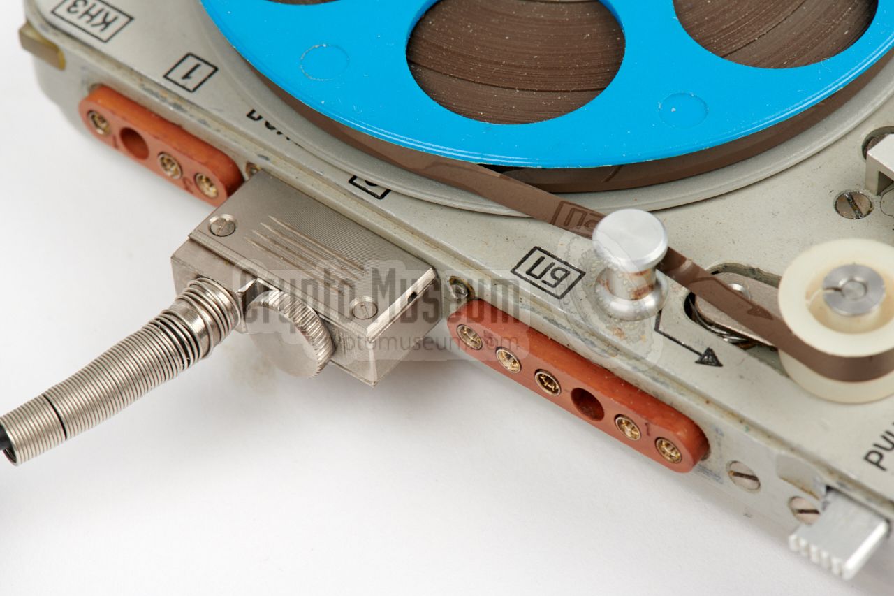
The sockets at the left side
are made of bakelite rather than plastic,
but are fully compatible with Nagra's plugs. Even the supplied
covert microphones can be used on
both recorders.
Yachta's interior was completely redesigned however.
|
|
|
The design of the recorder is based on the
Nagra SNST, which is the stereo
version of the Nagra SN.
It was developed in Ukraine — at the time part of the USSR — around 1987,
10 years after the introduction of the
Nagra SNST, and nearly 16 years after the original
Nagra SN. The latter was developed during the 1960s 4
especially for the US intelligence and law enforcement community.
Although it must have cost a fortune to develop Yavir/Yachta — a single unit was
probably more expensive than an original Nagra SNST — the Soviets didn't want
to order equipment from Nagra,
as that would likely have become known to
US intelligence,
given the good relationship between the US and Nagra.
Production started in 1987/88, and lasted for ~10 years,
during which time it was a popular item of
Soviet intelligence services
like the Russian KGB.
After the fall of the Soviet Union in 1992, the Ukrainian factory kept
producing the recorder under the name Yavir-1 [1].
|
 |
-
Also known as the Research Institute Manuilsky, today known as the
Space Research Institute (SRI).
-
Яхта (Yachta) is Russian for Boat or Yacht.
It was the KGB code name for the recorder. Note that Yachta was also
used as the codename of the
T-219 voice encryption device.
-
Явiр (Yavir) is Ukrainian for Sycamore, the European species of a maple tree.
-
The prototype of the Nagra SN was made in 1960,
but production first started in 1971.
The stereo version – Nagra SNST –
was first produced in 1977.
|
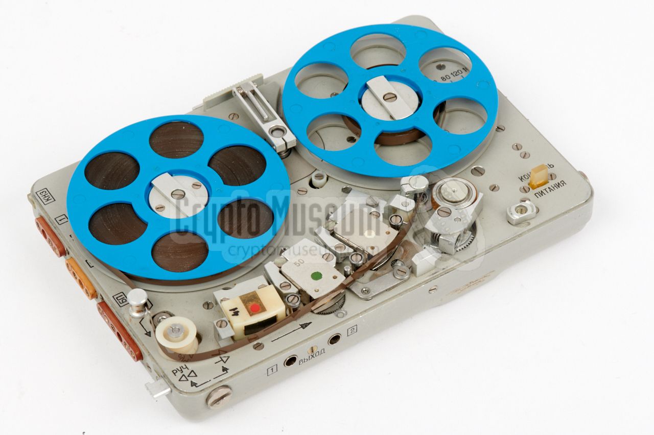
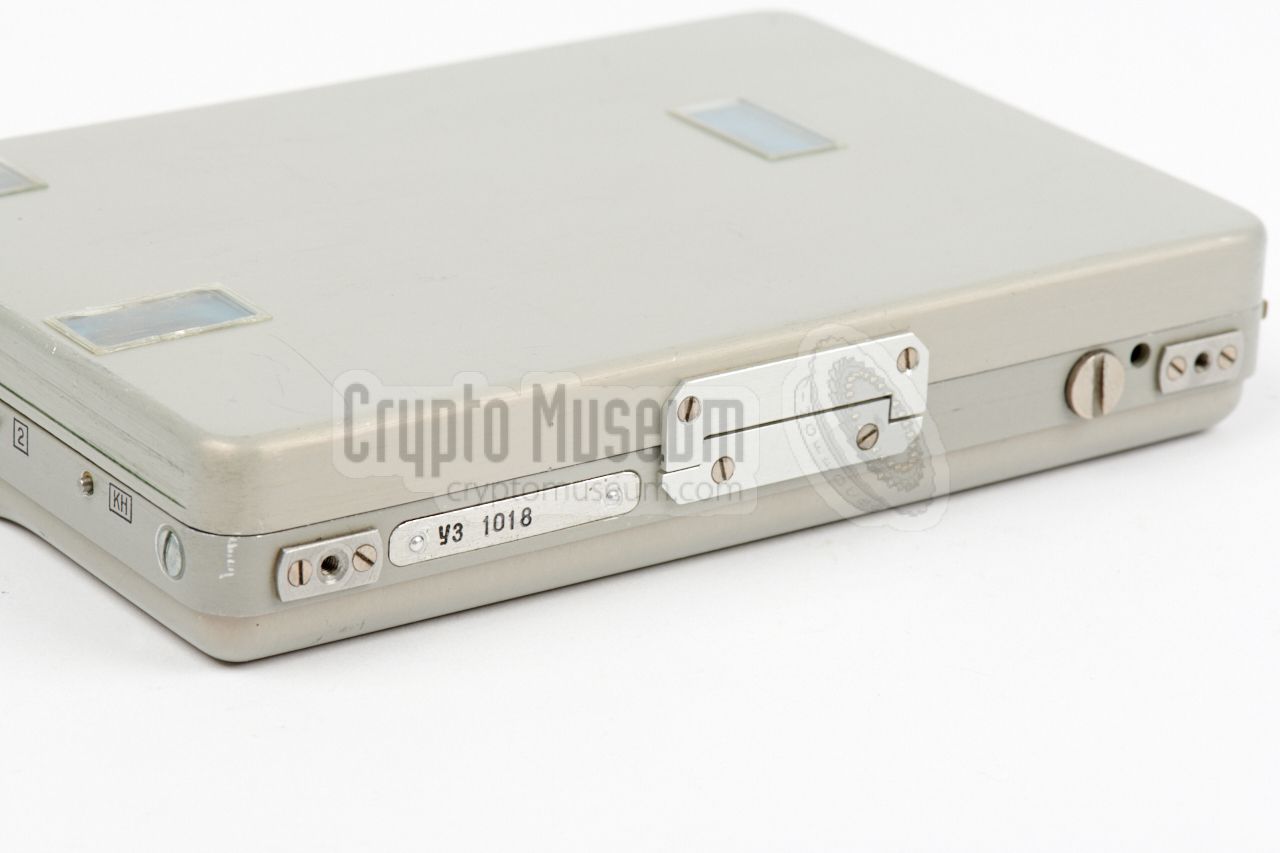
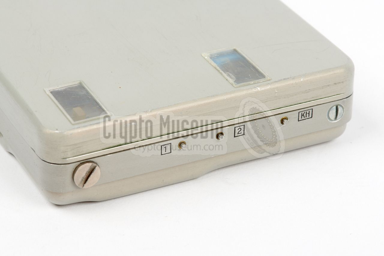
The image below gives an overview of the controls and connections of the
Yachta recorder. The sockets for connection of the peripherals are all at the
sides, with those for the microphones
and the external battery/remote
control unit at the left, and the busses for the earphones at the front.
All text on the recorder's body is in Russian and is
engraved in black, rather than screen-printed.
The tape heads and the routing of the tape past the guides, are similar to
those of the Nagra SN and SNST, with the most obvious difference being the
absence of a meter
at the bottom right. The meter — which on the Nagra is used
for checking the audio level as well as the battery level —
is replaced here by a simple LED indicator that starts flashing
when the voltage drops below 2.1V.
|
|
Yachta was commonly used in combination with a special playback device
— in Russian known as устройство воспроизвдения —
which is actually a clone of the
Nagra DSP-1 amplifier.
This device features audio expanders which match the
audio compressors inside the recorder.
|
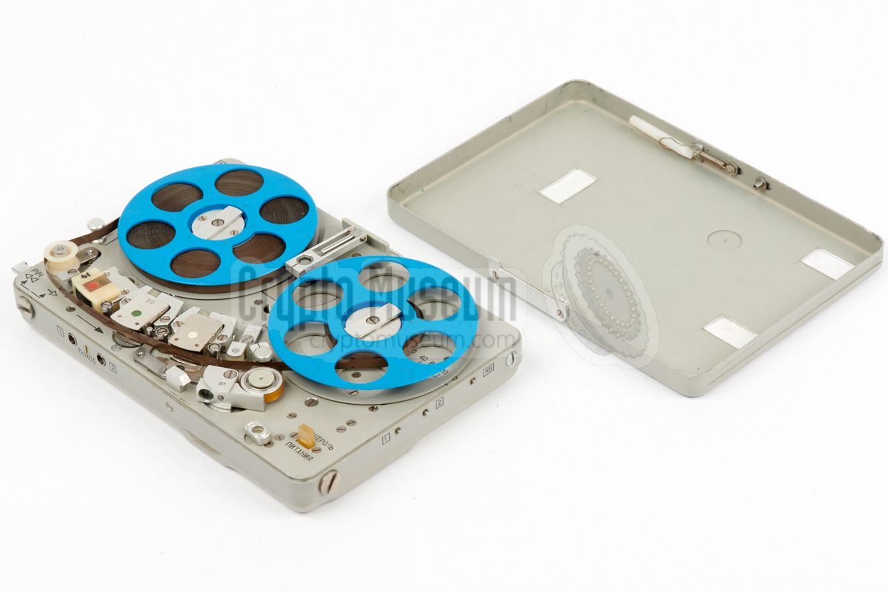
The designers of the Yachta recorder went through great length to copy
every detail of the Nagra SNST. As first sight, one might be led to believe
that it was actually manufactured by Nagra. When looking closer however,
there are some differences in quality, materials, tolerances in sizes,
the position of screws, etc. In addition, the
interior is completely different
as will be shown below.
The image above shows both the Yachta (front) and Nagra (rear). As we do
not have a Nagra SNST in our collection, we are showing the
Nagra SN instead.
The most obvious difference between the two recorders is no doubt the absence
of the meter at the bottom right. On Yachta, it is replaced by a power check
indicator (LED) that starts blinking when the battery voltage drops below 2.1V.
|
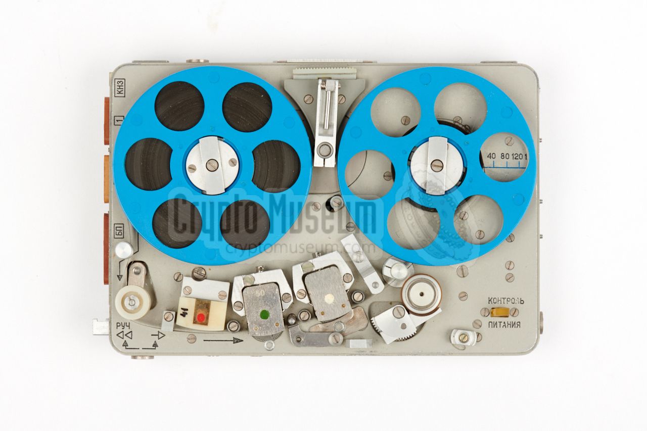
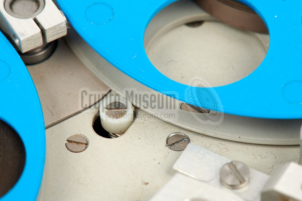
Furthermore, the shape of the transport locking knob is different. On the Nagra
it has the shape of a quarter circle, whilst on Yachta it has an oval shape.
Although the individual parts, such as the tape heads and guides, are at
exactly the same position on both recorders, the position of some of the
recessed screws is slightly different. One example is the screw in the yellow
circle above.
The springs that are used for the spring-loaded items,
such as the tape tension arm at the left, have a different strength,
as a result of which these parts will behave somewhat differently.
|
|
|
|
The spring that is used for the case lock is slightly too strong, as a result
of which the case lid can not be closed as easily as on the Nagra. The overal
impression is that some parts are less well finished and that the quality of
the materials is slightly lower. Nevertheless, the result is amazing.
|
The recorder is built on a machined chassis that is milled-out of a solid
block of aluminium. The outer case is eloxed, whilst the top surface is also
brushed. It is hard to tell the difference.
At the left side are the sockets for connection of an external power source,
a remote control unit and the microphones, all custom made to Nagra
specifications. On the Nagra, these sockets are
made of green plastic,
whilst for Yachta brown bakelite is used. Bakelite — a brand name for
a thermosetting phenol formaldehyde resin — was one of the first plastics,
developed in 1907 [4].
|
|
|
|
In the West, Bakelite was largely replaced by modern polymer plastics
during the 1960s, but in the USSR is was used throughout the Cold War,
until well after the fall of the Soviet Union. In fact, many connectors and
sockets that are used in the Russian space program today (2017) are still
made of Bakelite, probably because of its proven reliability and its
heat-resistant properties.
|
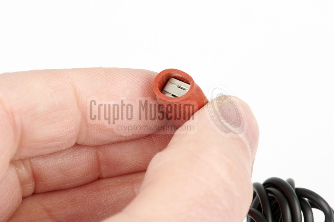
Yachta was supplied with two covert electret microphones — one for each
channel — that could easily be hidden under the operative's clothing.
They are protected by a rubber sleeve,
and are shown in the image on the right.
The microphones are connected to the recorder by means of a 3-pin plug at the
end of its cable, and are fully compatible with Nagra ones.
The electret elements are known as M1-B2 Sosna (Russian: Сосна),
which means Pine [2].
|
|
|
|
|
Fixed microphone(s)
wanted item
|
|
|
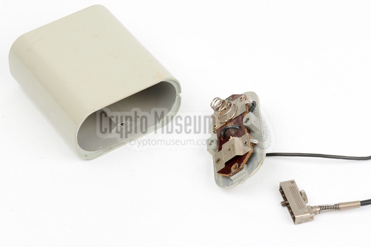
As an alternative to the external microphones shown above, the
set also came with two fixed microphones, in which the electret element
is mounted inside an enlarged plug.
The microphones can be
attached to the side of the recorder,
jut like an ordinary microphone connector.
Photograph kindly supplied by [1].
|
|
|
The recorded audio could be played back on Yachta via virtually any type of
earphones, such as the one shown in the image on the right, that was commonly
used in the USSR at the time.
Note that the audio volume is relatively low and that there is no volume
control. It was also possible to play the audio back via the special
self-contained audio amplifier, or via any other amplifier by using the
external adapter box.
|
|
|
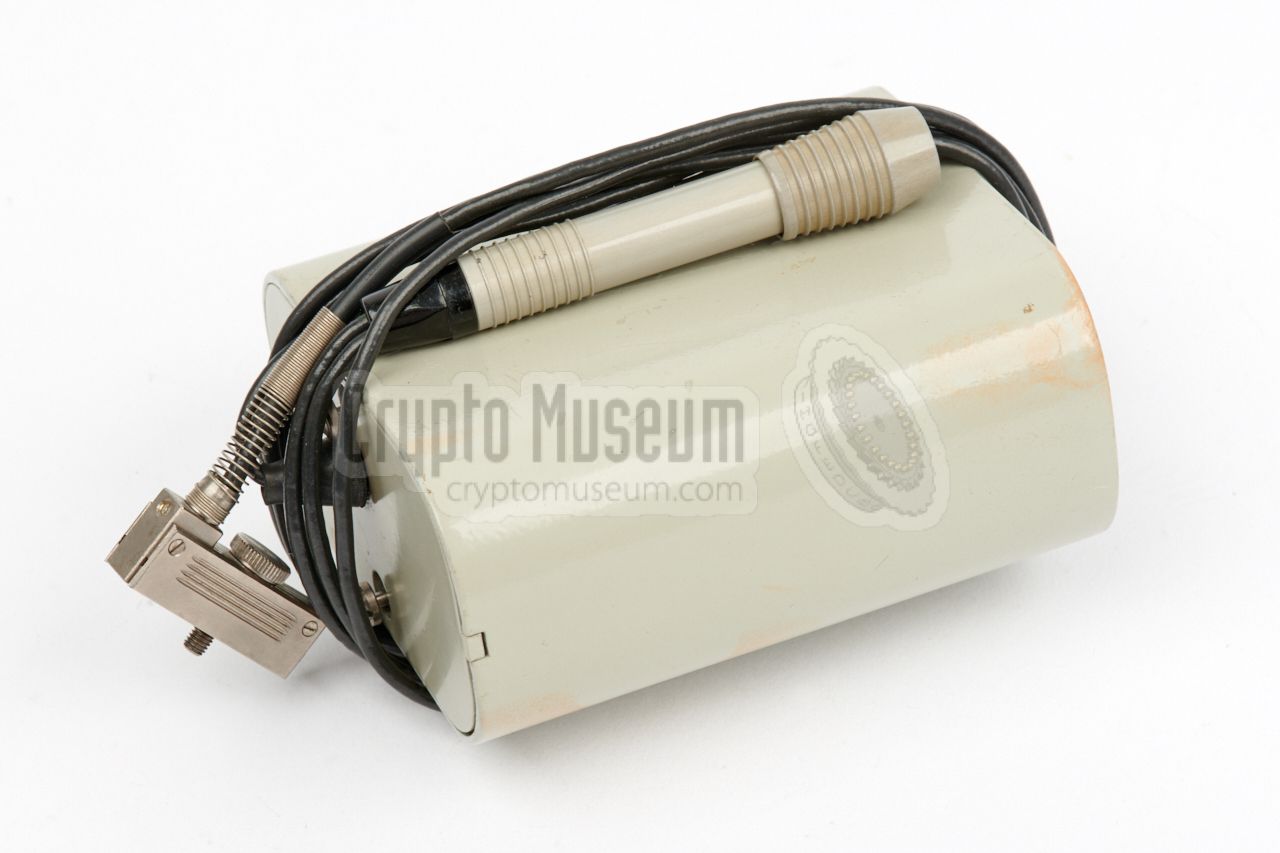
In order to extent the battery life of the recorder – for example in situations
where the record and playback function had to be used uninterrupted for several hours
– the external battery box shown in the image on the right was available.
The box accepts two large 1.5V C-size batteries (also known as mono-cells),
and has a long cable that connects to the remote socket of the recorder by
means of the 5-pin plug at the end.
The cable also holds a power switch that can be used as a hand-held start/stop
button.
|
|
|
The magnetic tape on which the audio signal is recorded, is identical to
that of the Nagra SN. It is 3.81 mm wide and is divided into two tracks.
The tape is supplied on a plastic reel, such as the one shown in the image
on the right. As the dimensions are identical, it was also possible to use
Nagra tapes and spools, which were also available in eloxed aluminium.
➤ See available tapes
|
|
|
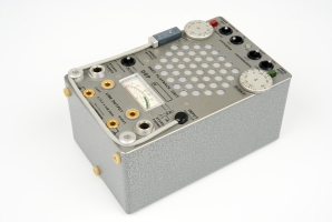
An external audio adapter, or galvanic separator, was available for
connecting Yachta's output to an external stereo audio amplifier, but it
should be noted that the audio signal on the tape is compressed and that
most amplifiers do not have a suitable expander.
The adapter contains two 1:1 transformers and delivers the outputs on a
5-pin 180° DIN socket.
|
|
|
The recorded signal can be played back via an external amplifier that
can be connected to the earphone sockets at the front of the recorder.
It was recommended to use the original Nagra DSP-1
or its Russian clone – which was named
устройство воспроизвдения
(playback device) –
as these have a built-in expander that properly recovers the recorder's
compressed audio signal.
➤ More information
|
|
|
|
|
Telephone pickup coil
wanted item
|
|
|
For covertly recording a telephone conversation, the pickup
coil shown in the image on the right was supplied as part of
the kit. The rectangular coil is placed under the
(analogue) telephone set
and picks up the stray magnetic field produced
by the transformer inside the telephone set.
Note that this is only suitable for
old analogue telephone sets.
Modern (electronic) ones, do not have a transformer that
produces an exploitable stray field.
Photograph kindly supplied by [1].
|
|
|
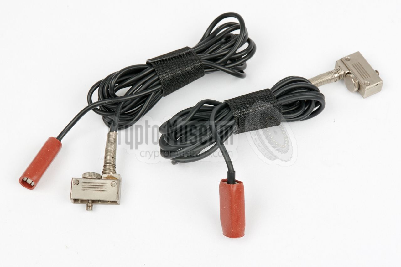
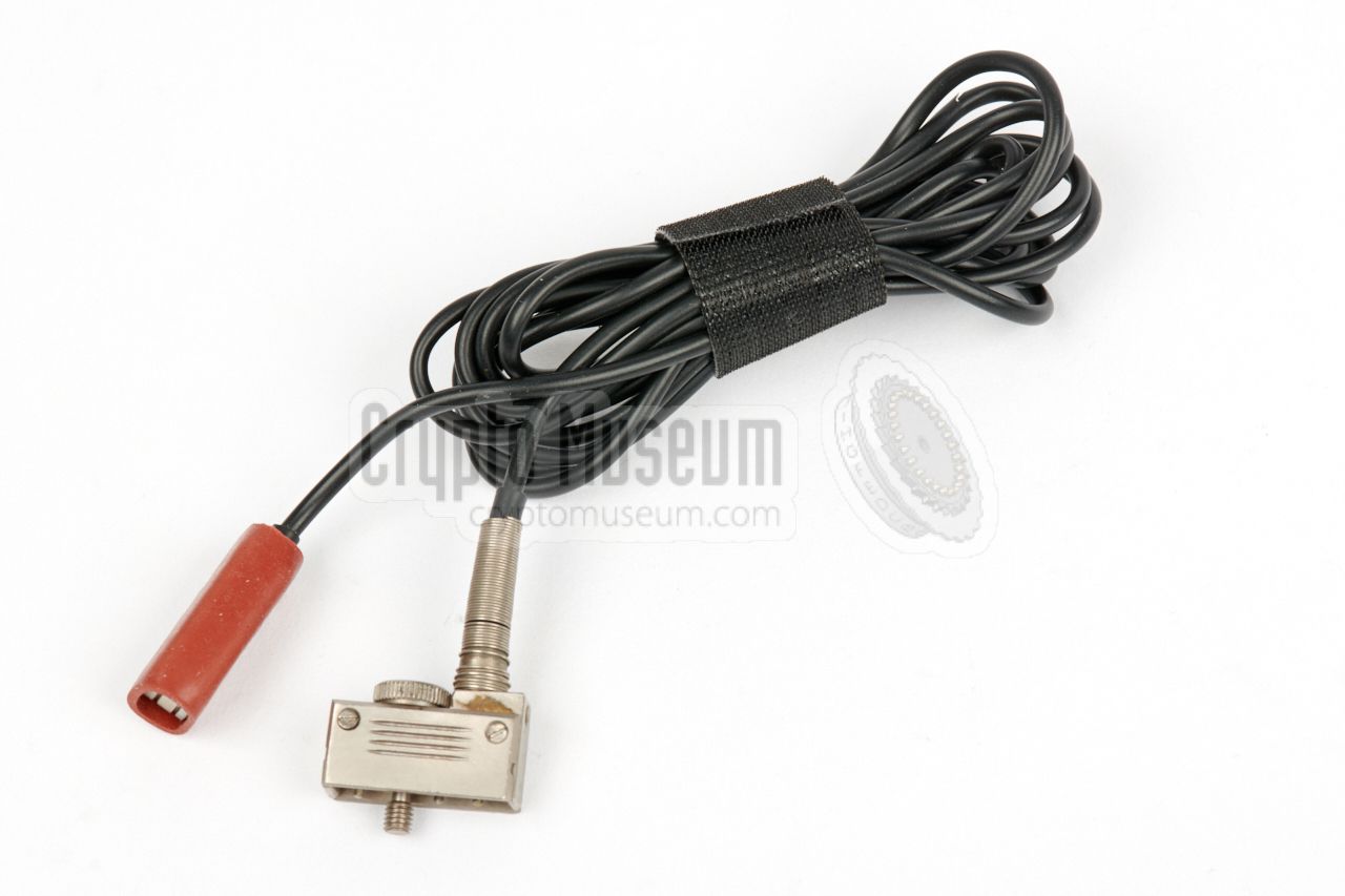
In some situations it was not possible to use the pickup coil
shown above for covertly recording a telephone conversation.
For such situations, the wire tapping tool shown on the right
was used.
The tool is not electrically connected to the wires of the
telephone line, but is clamped around the cable, where it
picks up the (weak) mangnetic stray field that surrounds
the cable during a conversation. The weak signal is then amplified
to normal microphone level.
Photograph kindly supplied by [1].
|
|
|
Below is the block diagram of the electronic circuits inside the
recorder. At the bottom left is the power supply, with is provided either
by two internal 1.5V AA-size batteries, or an external 3V DC power source.
A small micro-switch senses the presence of the external power plug, and
switches between the two sources. The power source is converted by a
step-up and stabilization circuit, to a constant +5V DC level.
The direct battery voltage is monitored by a warning circuit.
At the top left are two audio compressors, each of which amplifies the signal
from one of the microphones and compresses its dynamic range. The outputs
of the compressors are fed to the recording head, where they are mixed with
the signal from the bias generator. The latter also drives the separate
erase head. The recording circuit is activated by a small micro-switch
that is located at the side of the recorder.
It senses the presence of one/both of the microphone plugs.
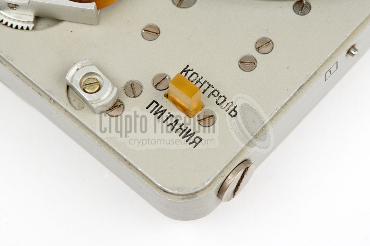
The playback circuit is always ON, so that the recorded signal
can be checked immediately, either through the earphones (output) or
via the check indicator, by pressing one of the signal
check push-buttons (1) or (2). The check indicator can also be used
to check the internal +5V DC level.
The block diagram above shows the motor driving circuit, which is completely
independent from the audio circuits. It consists of a motor, a motor driver
(20001) and a speed stabilization circuit (38004).
A tacho generator – mounted to the body of the motor –
delivers pulses to the input of a phase comparator, that compares it with
the signal from a crystal-driven reference oscillator. The error signal
from the phase comparator is fed to the driver, which controls the motor
voltage.
|
|
Although the exterior of Yachta is nearly identical to that of the
Nagra SNST,
the interior, and the electronic circuits in particular, are completely
different. The circuits are based on the Nagra SN design, but are built with
Russian components, including eight so-called micro-assemblies (ICs).
|
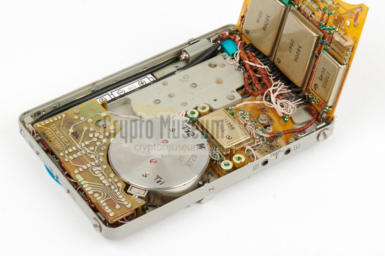
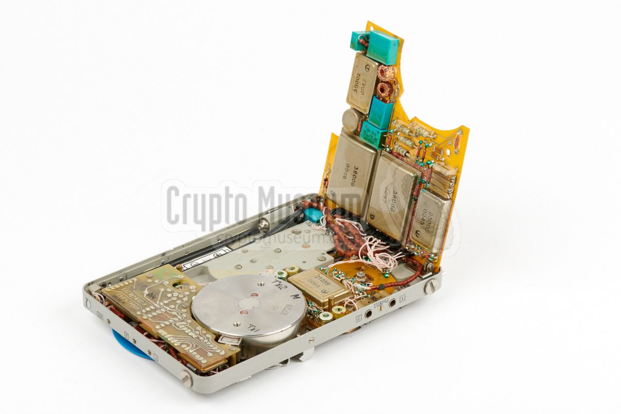
The interior of the Yachta can be accessed in the same way as Nagra: simply
by loosening the three large bolts at the sides, and
taking off the bottom cover.
This reveals the rear end of the motor and the solder side of
two circuit boards.
The smaller PCB
holds the motor driving circuit, whilst the larger one contains
the audio circuit
and the power converter.
The image on the right shows the
interior of the recorder after tilting the larger hinged board. The smaller
board to the right of the motor is the playback amplifier, that delivers the
signals for the two jack sockets.
|
|
|
|
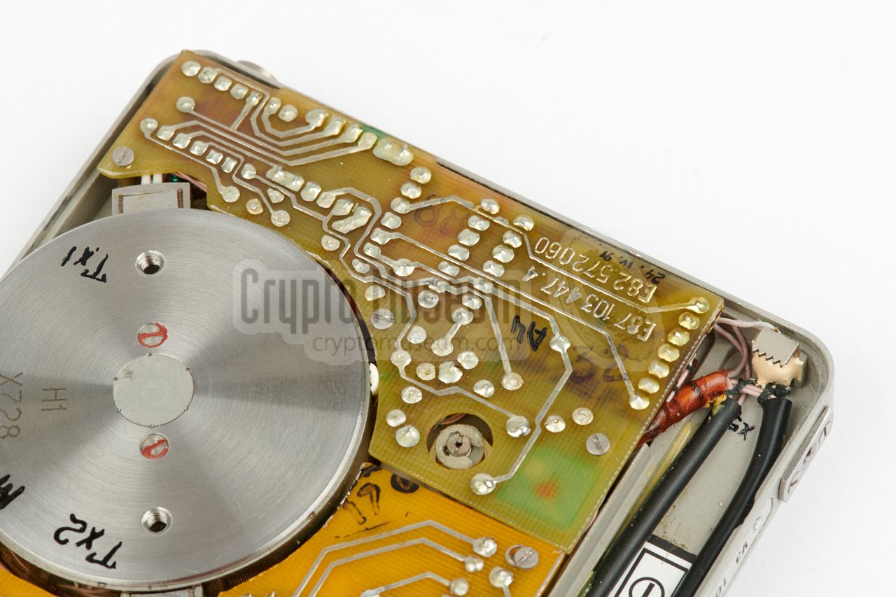
The circuits are nicely built, using first class Soviet parts, and are
interconnected by means of the typical Soviet
pink Teflon wire bundles.
Although the magnetic heads and the amplifier circuits are based on the
Swiss Nagra designs, Yachta's frequency response is less good and the recorder
does certainly not meet Nagra's design criteria. According to
markings on the PCBs,
the recorder featured here was built in June 1991, and
shows the state of technology in the USSR just before its collapse.
By that time, the world had moved on to SMD components, and Nagra had its
JBR.
|
|
Judging from the usage marks on the recorder featured here,
this Yachta has seen quite some action. When we first loaded the recorder
with fresh batteries, it didn't work and the batteries became hot immediately.
Fortunately, this was just an intermittent failure that was easily fixed.
|
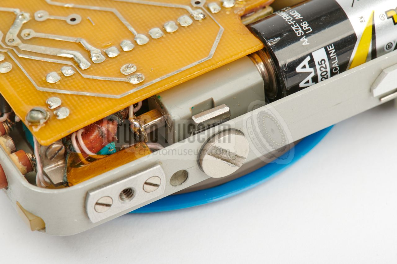
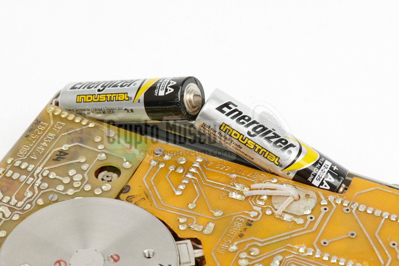
The pink wire of the (+) terminal of the battery compartment,
was broken. Furthermore, the (+) terminal could be shorted to ground,
due to two manufacturing flaws that will only expose themselves
when using modern 1.5V AA batteries.
As modern AA-size batteries are about 0.5 mm longer than the batteries of
the 1980s, they will hardly fit the battery compartment, as there is no
tolerance whatsover. As a result, the spring of the (+) terminal will be
fully compressed, and the (+) is pushed all the way towards the chassis
where it touches a metal supporting bracket.
|
|
|
|
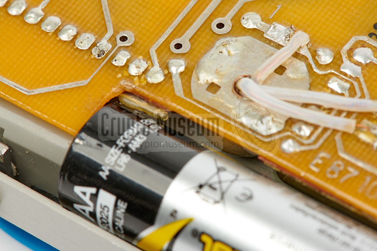
This problem can easily be fixed. The wire can be resoldered to the spring
of the (+) terminal, and a piece of Mylar tape can be used to isolate the
metal support bracket, as shown in the image above. The latter can also be
fixed by milling off the corner of the metal support bracket.
|
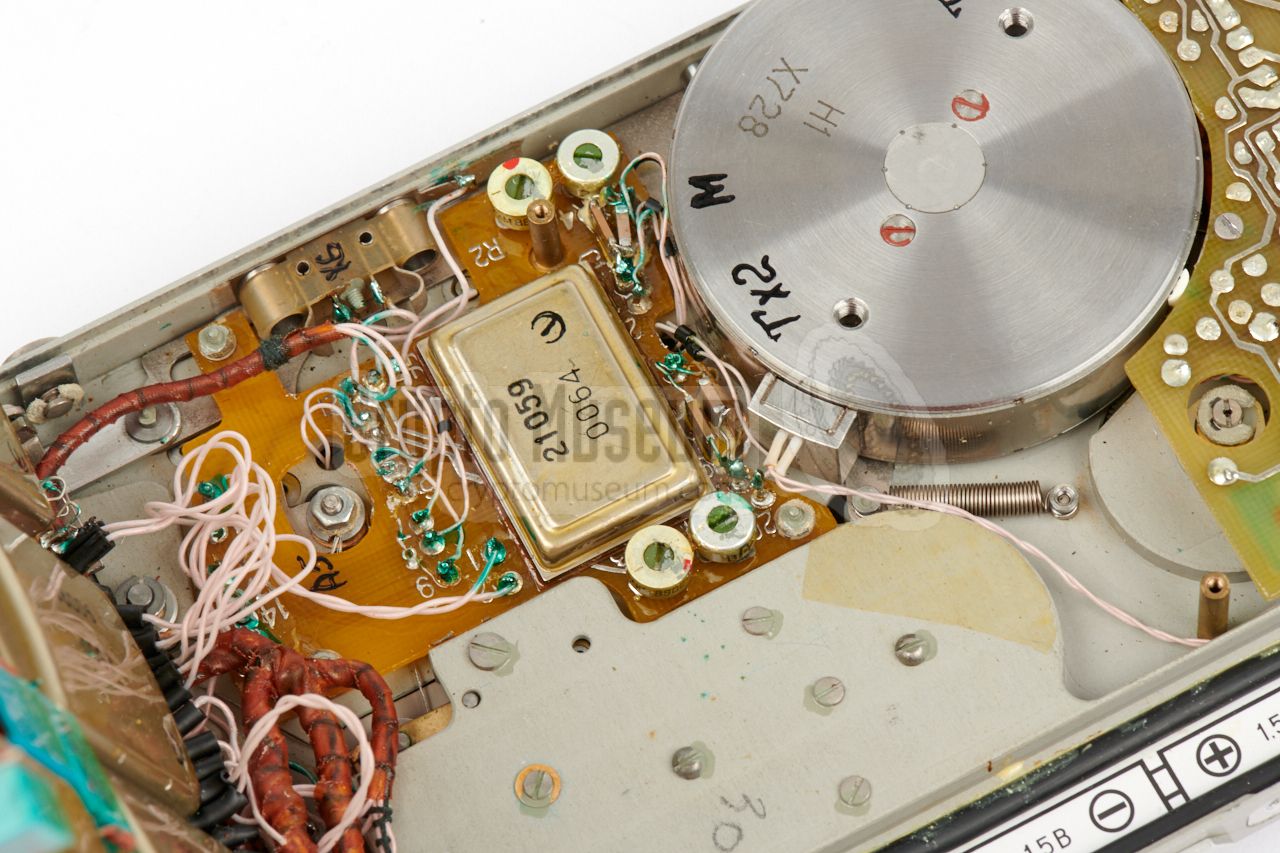
Another problem is caused by the metal case shell of a
micro-assembly (IC), that is located close to the (+) terminal of the battery.
Although the case is isolated with a conformal coating, it is pretty sharp and
can easily damage the thin isolation of an AA-size battery when inserting it.
Depending on the construction of the battery, either the (+) or the (-) side
becomes connected to the IC's case shell and will cause a full short circuit.
In addition, Alkaline batteries have a high energy density and may catch fire. This problem can be avoided by
installing them as shown here.
|
|
|
|
Although the battery compartment is copied from the Nagra design, the
dimensions are slightly different, and the battery compartment of the Yachta
is far less tolerant to battery size variations. Always be careful when
installing new batteries and do it as shown in the images below. Avoid
using excessive force and metal aids, such as a screwdriver,
as this will damage the isolation.
|
|
The following accessories were available for the Yachta/Yavir recorder:
|
Device Stereo tape recorder Purpose Covert recording of conversations, wire tapping Model Yachta-1M (Яхта-1М) Codename Yavir-1 (Явiр-1) Manufacturer Special Machinery Factory, Kiev (Ukraine) 3 Year 1987 Country USSR (Ukraine) Users KGB,MVD, others Voltage 2 - 3V Current 120 mA (at 2.5V) Batteries 2 x 1.5V AA-size Tape width 3.81 mm Tape speed 2.38 cm/s Tape thickness ➤ see table Recording time ➤ see table Frequency response 170 Hz - 6000 Hz 2 Harmonic distortion ≤ 3% Wow & flutter ≤ 0.35% Dimensions 156 x 103 x 27 mm (body: 148 x 101 x 27 mm) Weight 600 grams (without batteries and tape)
|
-
Obtained from
Vintage Technics website
[1].
-
The frequency response is reported by some sources as 280 Hz - 3950 Hz ±3dB [2].
-
Also known as Research Institute Manuilsky, now: Space Research Institute (SRI).
|
9 µm 270 m 3:08 hrs 12.5 µm 217 m 2:32 hrs 18 µm 150 m 1:44 hrs
|
|
We are still looking for the following items. If you can supply
any of these, please contact us.
|
- Internal microphones
- Telephone pickup coils
- Remote control unit
- Playback device
- Power supply unit
- Audio adapter
|
-
Used in the playback device.
|
|
|
|
Any links shown in red are currently unavailable.
If you like the information on this website, why not make a donation?
© Crypto Museum. Created: Thursday 21 December 2017. Last changed: Saturday, 13 December 2025 - 10:19 CET.
|
|

|
|
|


![Fixed microphones. Photograph kindly supplied by [1].](img/302786/085/full.jpg)


![Adapter for external amplifier. Photograph kindly supplied by [1].](img/302786/082/full.jpg)

![Telephone pickup coil. Photograph kindly supplied by [1].](img/302786/080/full.jpg)
![Wire tapping tool. Photograph kindly supplied by [1].](img/302786/077/full.jpg)


