|
|
|
|
|

|
|
Covert DF KGB GRU Stasi
|
The recorder allows the conversation — usually in a different language —
to be translated and transcribed later. The external recorder
can be started and stopped from the RCU,
which also allows the speaker to be used as a
microphone, so that the agent can add a verbal comment to the recording.
The device is normally used with a simple wire antenna
that is affixed to the clothing by means of safety pins,
and connected to one of the two antenna inputs (25 or 90).
|
The receiver was used by Soviet and Warsaw Pact
field agents, to check whether they were being followed
by their foreign counterparts, in which case the adversary
agents were most likely using covert radio sets
hidden under their clothing.
As the receiver is only sensitive to strong nearby radio signals — in particular
transmissions in the 150 and 400 MHz bands —
it provides a good means for detecting foreign agents.
If a signal is picked up, the speaker produces a
2 kHz tone, which promts the operative to abort the mission, or
continue the surveillance detection run. 2
|
|
|
-
Копчик (Kopchik) is the russian word for coccyx (tailbone).
-
In espionage, covert agents commonly follow a complex procedure — consisting
of walking, using public transport, changing direction, etc. — to ensure
that he or she is not being followed by adversary observers. This procedure
is commonly known as a surveillance detection run.
|
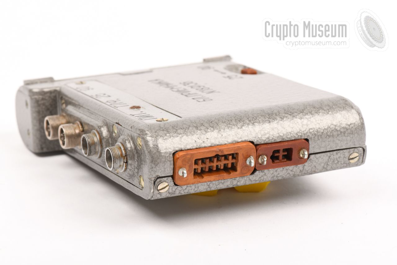
The diagram below gives a quick overview of the controls and connections
on the body of the Kopchik receiver. The text on the body
(БЛ. ПРИЕМНИКА) means RECEIVER BLOCK. The device is powered by a
rechargeable NiCd battery pack
that should be installed
behind the curved lid
at one side, or by an external DC source connected to the socket
marked ПИТ. (pitaniya, supply).
The device is operated by means of a remote control unit (RCU)
that is held in one hand, with the cable guided through the sleeve of the coat.
It is switched ON/OFF from the remote control unit.
A simple antenna should be connected to the
25-socket (for narrowband) or to the 90-socket (for wideband) reception. It can be fixed to the clothing
by means of safety pins. Due to the non-selective (aperiodic)
nature of the receiver, it is
responsive to strong nearby signals only, in which case it will produce the
demodulated sound (AM only) or an audible 2 kHz tone (FM, SSB and CW).
The demodulated sound is reproduced through a standard Soviet
NEVA speaker,
which can also be used as a microphone, in case the (optional) recorder is
connected to the 4-pin socket at the side.
The start/stop function of the recorder is under control of an internal
miniature relay.
|
The image on the right shows the bare Kopchik receiver, which was identified
in the checklist as RECEIVER BLOK (БЛ. ПРИЕМНИКА). It could be
carried in a pocket of the coat, but was usually worn directly on the body,
using a cloth harness.
The receiver is powered by an internal battery or by an external power
source, such as a mains power supply unit (PSU) or the battery of a car.
As a bare minimum for operation, it needs an
antenna,
a speaker
and the remote control unit.
|
|
|
The receiver can only by used when the
original remote control unit (RCU)
is installed in the 12-pin socket at the
left side.
It is usually carried in the hand.
The receiver is powered by sliding the switch towards the bottom
of the RCU to the left.
For a first check,
it is recommended to shift the Volume switch (Р.Г.) to the
loudest position (Б
= Больше, more) and the reception switch
(ПРИЕМ) to the centre position.
At the rear
is a switch for selecting ТЛГ (telegraphy, morse, tone),
or ТЛФ (phone) for demodulating AM.
|
|
|
For reproduction of the demodulated sound, a Soviet standard-issue NEVA
speaker is supplied with the receiver. It is the same speaker that was
supplied with nearly all direction finders
and covert radios of the era.
NEVA can be affixed under the collar of, say, a coat, and can also be used
as a microphone, which in this case might be usefull when using an
(optional) external recorder.
|
|
|
As Kopchik is only intended for detection of radio signals in close
proximity of the operator, a simple short wire will usually be sufficient
as an antenna. The image on the right shows a typical 50 cm wire that can
be connected to either of the inputs (25 or 90).
The wire antenna has several safety pins, to allow it to be affixed to the
clothing. In most cases, it should be worn vertically.
|
|
|
For simple direction finding tasks, and for the detection of horizontally
polarised signals, the simple (wire) dipole antenna shown in the image on
the right might be used as an alternative to the regualar antenna.
The antenna shown here, has a built-in adjustable blocking filter, that
can be used to block a specific frequency.
|
|
|
Kopchik was powered by a rechargeable NiCd battery pack,
that should be installed behind the
curved hinged lid at the side.
We are currently unable to show a picture of the original battery,
as it is missing from the device featured here.
As an alternative, the
device can also be powered via the ПИТ. socket at the top. Note that
the (+) terminal should be connected to ground (i.e. to the metal of the case).
|
|
|
During a covert operation – for example during a surveillance detection run –
Kopchik was usually carried in a purpose-made cloth harness, that allows it
to be hidden easily under the clothing.
We are currently unable to show a picture of the cloth harness, as it is
missing from the device featured here.
|
|
|
Although Kopchik can be used with virtually any type of audio recorder,
it was most likely used in combination with the body wearable
Mezon wire recorder shown
in the image on the right.
Mezon can record many hours of sound onto a very thin steel wire, and was
also developed especially for the
Soviet intelligence services.
➤ More information
|
|
|
It is possible that in later years, Kopchik was used with a covert tape
recorder, such as the Yachta device
shown in the image on the right.
Yachta is in fact a clone of the 1960s
Swiss Nagra SN,
and was released in 1987, at a time when the
original Nagra SN
had been replaced by smaller devices and was no longer in production.
➤ More information
|
|
|
|
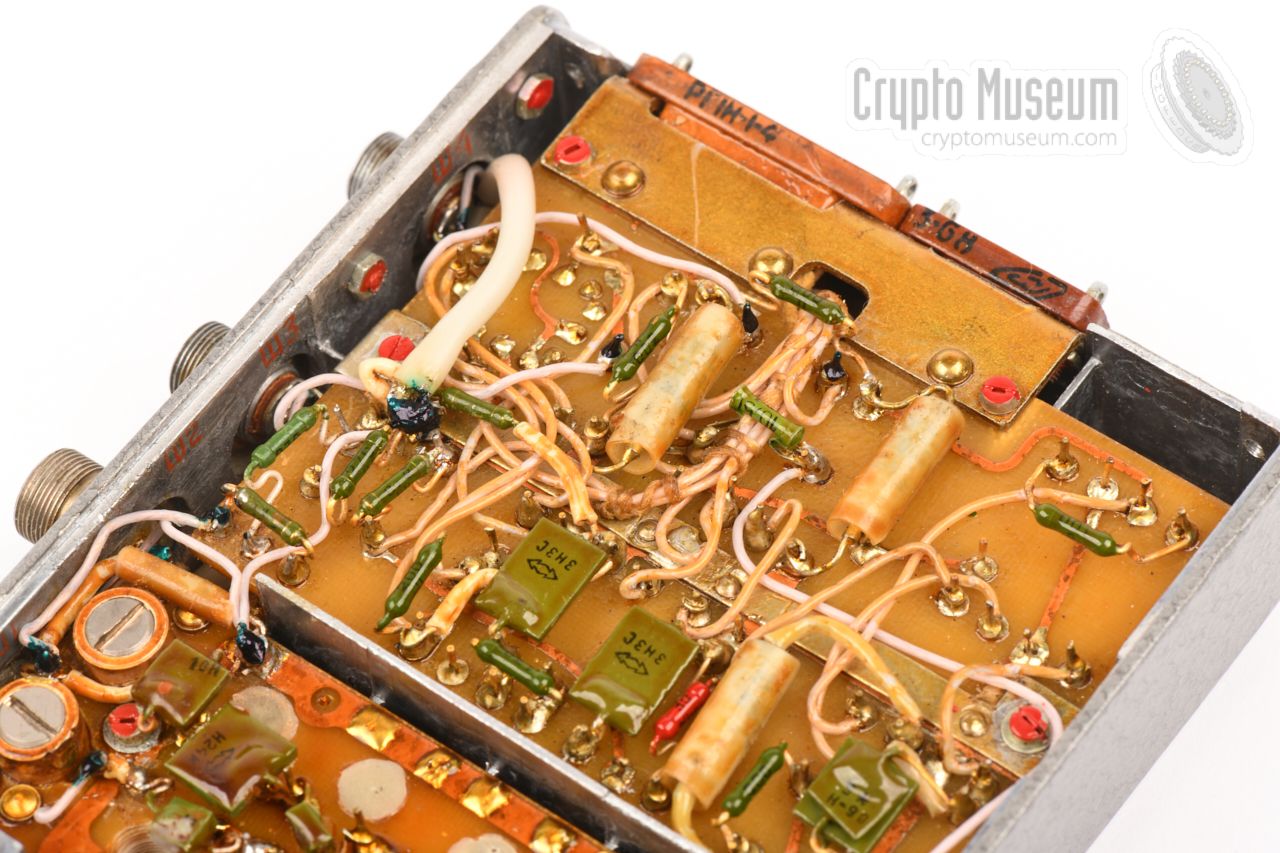
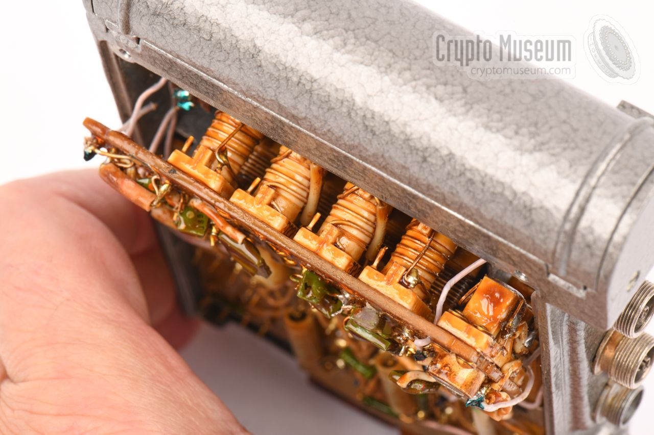
All sub-circuits are interconnected by means of typical (Soviet) pink
teflon wiring, largely via the 12-pin remote control socket at the
side of the receiver.
Inside the remote control unit (RCU) are a number of
Soviet-made microswitches, operated by sliding metal frames. The construction
is very similar to that of the more versatile
Sinitsa,
which is also a body-wearable aperiodic receiver.
|
Below is the simplified block diagram of the Kopchik receiver. At the left
are the antenna inputs; one for each bandwidth: 25 kHz (narrowband) or 90 kHz
(wideband). The antenna signal is mixed with the square wave signal from a
free-running low-frequency (LF) generator, running at 2 kHz or 20 kHz.
The 2 kHz signal is in the audible range and is used when the slide switch (S2)
at the rear of the remote unit is set to ТЛГ (TLG, telegraphy, CW).
It can also be used for the detection of FM signals. The 20 kHz generator is
selected when the switch is set to ТЛФ (TLF, telephony, AM).
The output of the mixer is passed through a
bandpass filter onto a diode detector.
There are two separate input branches, optimised for
narrowband (25 kHz) and wideband (90 kHz) respectively, selectable with a
slide switch (S3) on the body of the device, marked 25↔90. The resulting
audio signal is then optionally muted (S4), amplified and passed to the speaker.
The audio signal is also available for an
externally connected recorder,
under control of a 3-position switch (S5) (ПРИЕМ).
When switch S5 is set to МАГН (MAGN, recorder),
the demodulated audio signal is passed to the recorder.
In the position МКФ (MKF, Microphone), the speaker is used as a microphone,
so that the operator can add a spoken message to the recording.
The receiver is powered by an internal battery, or by an external 4.5 to 7.4V
DC voltage, connected to the socket marked ПИТ. (PIT, pitaniya, supply).
Note that the (+) terminal of the battery is connected to the case (ground).
|
Due to the way in which the antenna input circuits of the receiver are
dimensioned, the device is particularly sensitive to signals in the 150 MHz
VHF band and the 400 MHz UHF band, both frequencies that were commonly used
at the time for covert agent-to-agent communication.
The diagram above provides a rough indication of the sensitivity of the
receiver.
|
|
|
|
Any links shown in red are currently unavailable.
If you like the information on this website, why not make a donation?
© Crypto Museum. Created: Saturday 22 October 2016. Last changed: Wednesday, 05 November 2025 - 11:45 CET.
|
 |

|
|
|


