|
Opto Voice ZEISS Stasi FINOW → ← JO-4.02
The system consists of a local and remote JO-4.03 unit,
an expansion unit, a power supply unit (PSU) and various
accessories, and was supplied in a large unobtrusive travel suitcase.
The bare (closed) device measures just 170 x 120 x 50 mm and weighs 1452 grams.
It has three spring-loaded flaps that protects the lenses agains direct sunlight.
After opening the largest flap at the front, the two flaps at the sides come out
automatically, as shown in the image on the right. At the bottom is a ball-head
that allows the device to mounted on a tripod.
|
|
|
At the top is an enlarging viewfinder that has the accuracy of a riflescope.
It is used to aim the device accurately at the remote station.
Once the flaps are opened, a horizontal bar with two small embedded mirrors
must be raised before the device can be used. The complete unit, with
microphone, earpiece and accessories is packed in a
compact black leather storage case.
Two such sets are present in the kit.
A 45° persicope
is provided for adjusting the device from any angle.
Normally, an agent would only take one unit in his luggage on a trip to the
free West, and use it to pass information to a Stasi station inside the
DDR in the direct Line-of-Sight (LOS).
The JO-4.03 was specified for a LOS operational range of up to 3 km [A],
but amateur radio operators have meanwhile demonstrated that under good
conditions a much longer range is possible [5]. When using the auto-recording
and high-speed audio transfer features, the maximum range is restricted
to 2 km. Note that only one station transmits a 16 kHz pilot tone.
|
 |
-
The Dahme is a river that flows in the German states of Brandenburg
and Berlin. The Stasi commonly used river names for its infra-red
(IR) communication devices. As Dahme is pronounced the same as the
German word Dame (lady), the name was easily transformed into Kleine Dame
(little lady).
|
A complete system consists of two transceivers (devices 1 and 2) – also known
as the main units –
an expansion unit (3) and a power supply unit (4).
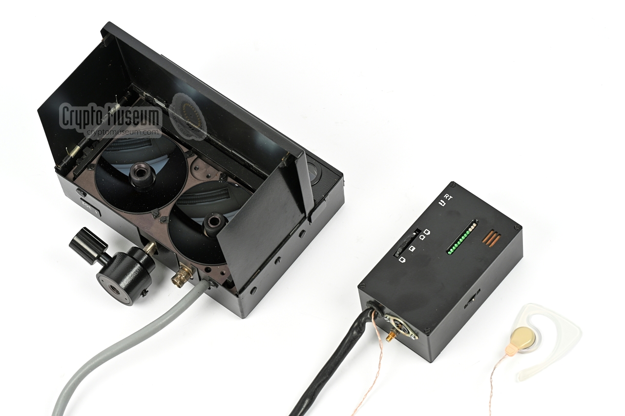
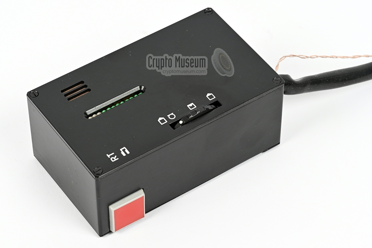
The image below shows one of the main units (device 1), with its control unit
and earpiece. The control unit, or handset, holds the batteries (3 x 1.5V AA-size),
the microphone, a wired earpiece, the MODE-selector and the volume control with
on/off switch. It is connected to the main unit via a 14-pin Amphenol
connector.
The main unit is housed in a rectangular black metal enclosure with a ball-head
at the bottom for mounting it on a tripod. At a front is a hinged
spring-loaded cover that protects the optics. When it is opened, the two
spring-loaded side panels will unfold themselves and expose the two large
parabolic primary mirrors.
Above the mirrors is a bar that holds the two small secondary mirrors.
Raise the bar to bring the
secondary mirrors in a locked position above the primary ones.
The diagram below shows the result. Note that the mirrors
consist of a glass body that acts as an infra-red bandpass filter and as a
lens. The reflective layer is at the rear of the glass body.
Install the device on a tripod and aim it accurately at the
other station, using the built-in rangefinder (above the hinged cover).
Note that the opening angle (2ω) is just 0.14°.
At a distance of 2 km, this is equivalent to approx. 10 metres.
Turn the device on by turning the volume control knob away from its
null-position (click) until a faint noise can be heared. The device is now
ready for use. When speaking into the microphone, the signal can be
picked up by the other station.
|
If necessary, the other station can be called by pressing the
red button at the left side
of the control unit. This sends a 1000 Hz tone to the
other station. Note that transceiver (1) always transmits a 16 kHz
pilot tone with the speech. This pilot tone can be used by the other
station (2) to start a tape recorder. Note that this reduces the
maximum range from 3 km to approx. 2 km.
|
The block diagram below shows the basic setup of the JO-4.03. A complete system
consists of two units known as (1) and (2), each of which is placed at one end
of a free-space transmission path. Note that a direct line-of-sight (LOS)
between the two units is mandatory. The opening angle is very narrow (0.14°),
so use the viewfinders at both ends to ensure that the devices can
'see' each other. When correctly adjusted, a distance of several kilometres
should be possible.
|
| |
Basic full-duplex setup with battery-powered units
|
In the basic configuration, each unit is powered by internal batteries
(placed inside the RCUs), or from a 4.5V flashlight, simply by connecting the
flashlight cable
between the E10 lamp fitting of the flashlight and the
small SMC coaxial socket on
the remote control unit.
|
In the advanced setup, the remote system (1) is battery powered, whilst the
local system (2) is powered by the mains power supply unit (PSU) (4),
via the supplied expansion unit (3).
The PSU can also be powered by a 12V DC source.
This situation is shown below. Note that the Expansion Unit (3) is connected
between remote control unit (2) (the handset) and the local transceiver (2).
|
| |
Advanced setup with external power and recording facility
|
In this setup, normal full-duplex voice transmissions are possible, just as
in the basic setup. But it is also possible to use the local system (2)
as an unmanned auto-recording station. It allows the voice transmissions from
the remote station (1) to be recorded onto an external UHER recorder.
In this configuration, the local station (2) can be used as an
electronic dead letter box (EDLB).
It allowed an agent to deliver his message without the need to establish
a two-way contact first.
Automatic recording is possible by the virtue of a 16 kHz pilot tone –
transmitted by unit (1) – that activates a recorder
that is connected to the local station (2). Unit (1) is the only unit that
generates a pilot tone, so it is important that this unit (1) is used
at the remote end. Its serial number has a '1' prefix.
When the 16 kHz pilot tone is picked up by the local station, this is
confirmed by a continuous 1 kHz tone.
After 30 seconds, the recording stops and so does the 1 kHz tone.
If the remote signal (1) is lost, the tone becomes intermittent.
In the same vain, when configured apropriately,
the remote station (1) can also be used to collect
pre-recorded messages from the tape recorder at the local station (2).
|
WARNING —
When the external power supply unit (4) is connected to the setup,
the batteries have to be removed from the handset (RCU 2) as they
will otherwise be damaged. The PSU
itself can be powered from the mains, by internal batteries, or by
an external 12V DC source, such as the battery of a vehicle.
 |
|
High speed audio transfer
|
|
|
It is also possible to transfer audio information at high speed
from the local station (2) to the remote station (1). It allowed
the Stasi to pass long instructions to its agent across the border,
whilst minimising the risk that the agent was discovered.
In this setup, a recorder at station (2), plays the tape at
2x or 4x the nominal speed.
Station (1) can then record this information at
2x or 4x the regular speed and play it back later at nominal speed.
This is also known as data mode. It has a bandwidth of 7 - 70 kHz,
and requires the BNC sockets on units (1) and (2) to be used.
|
| |
Setup for high-speed data transfer (data mode)
|
Note that the data signal can only be sent from unit (2), as unit
(1) always transmits a 16 kHz pilot tone. When a second recorder
is present at station (2), it can record the voice data transmitted
by station (1), whilst station (1) is recording the high speed data
from station (2).
Note that the local station (2) will automatically start playing its
high-speed message when the 16 kHz pilot tone from the remote station
(1) is detected.
|
|
Below is an audio sample of the JO-4.03, recorded by collector
Karsten Hansky in Germany in August 2025 [2]. The device picks up
and records the sound from another JO-4.03 that is 4 km away.
The recording was made late in the afternoon on 16 August 2025,
just before dusk.
|
Each of the main units (device 1 & 2) is stowed in a leather
storage case that measures 255 x 175 x 110 mm and weighs 2785 grams
(all items included). Inside the case is a transceiver, a control
unit (the handset), a power cable and maintenance tools
(cloth and brush).
An agent would normally travel abroad with just this case
in his luggage. In most cases, the case would contain device number 1,
as this is the only one that transmits a 16 kHz pilot tone.
|
|
|
The transceiver is the heart of the system. When closed, it measures
just 170 x 120 x 50 mm and weighs 1455 grams. When the flaps are opened,
it measures 170 x 120 x 135 mm. After opening, the secondary mirrors must be
brought in position by raising the bar (as shown here).
At the bottom is a ball-head with regular thread to mount it on a
tripod. The device has a fixed (grey) cable with a 14-pin
Amphenol connector at the end, to which the control unit must be
connected.
|
|
|
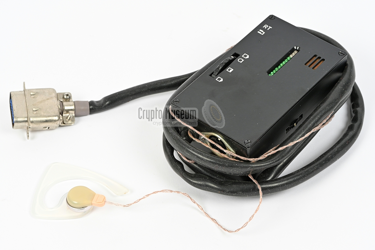
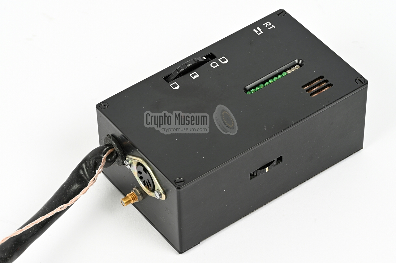
The device come with a control unit, or handset, that measures 115 x 62 x 44 mm
and weighs 350 grams. It has a fixed (black) cable with a 14-pin Amphenol
connector at the end that mates with the connector of the transceiver.
The handset contains a microphone, a mode-selector, a volume indicator (LED
bar) and a call button, and has a fixed earpiece. It allows full-duplex voice
conversations. When pressing the call button, a 1000 Hz tone can be heared at
the other end. All audio signals are also
available on a 5-pin DIN socket at the bottom.
|
|
|
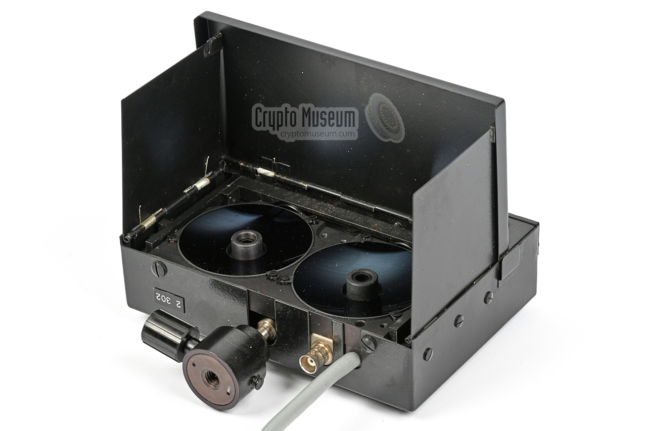
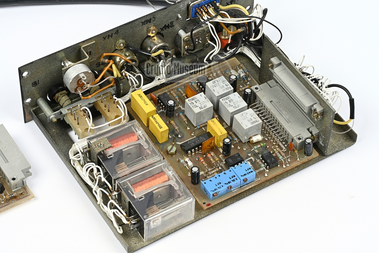
Although both devices can be used stand-alone (transceiver + handset),
device number 2 was usually connected to the expansion unit shown in the
image on the right. It can be connected to the
power supply unit (4) (see below)
and has sockets for connection of an external recorder.
The device is designated device number 3.
The cables are wired for connection of an
UHER Report 4000 audio tape recorder.
➤ Look inside this unit
|
|
|
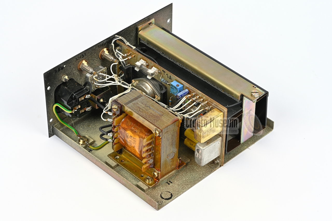
The device could be powered from the AC mains by means of the supplied
power supply unit (PSU) shown in the image on the right. It is designated
device number 4 and is suitable for the 200-250V AC mains only.
The device must always be connected to the transceiver via the
expansion unit (device 3) by means of a special power cable that was supplied
as part of the kit.
➤ Look inside this unit
|
|
|
If the eyepiece is unreachable, the periscope shown in the
image on the right can be used to aim the device at the counterpart
station. It should be mounted instead of the existing eyepiece – for which a
suitable tool is provided – and can be used at any angle of rotation.
Instructions on how to mount the periscope, are given in chapter 6
of the user manual [A].
|
|
|
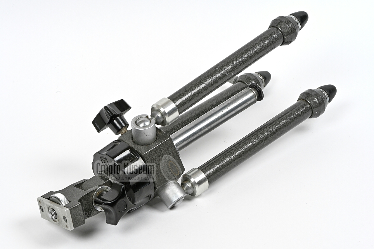
The JO-4.03 has an opening angle (2ω) of just 0.14°, which means that
both devices must be aligned accurately to achieve a proper and reliable
communication path. At a distance of 2 km, it illuminates just a 10 metre cone.
For a proper and stable link, it is therefore mandatory to mount the two
devices on a tripod, such as the one shown in the image on the right.
|
|
|
The JO-4.03 was supplied with a collection of cables, such as a mains
power cable, a cable for connection to the 12C battery of a car, an
interconnection cable used between device (3) and (4) and one or more DIN
cables for connecting the (optional) UHER tape recorder(s).
These cables are all intended for use at the local station.
In addition, each station comes with a special power cable (see below).
|
|
|
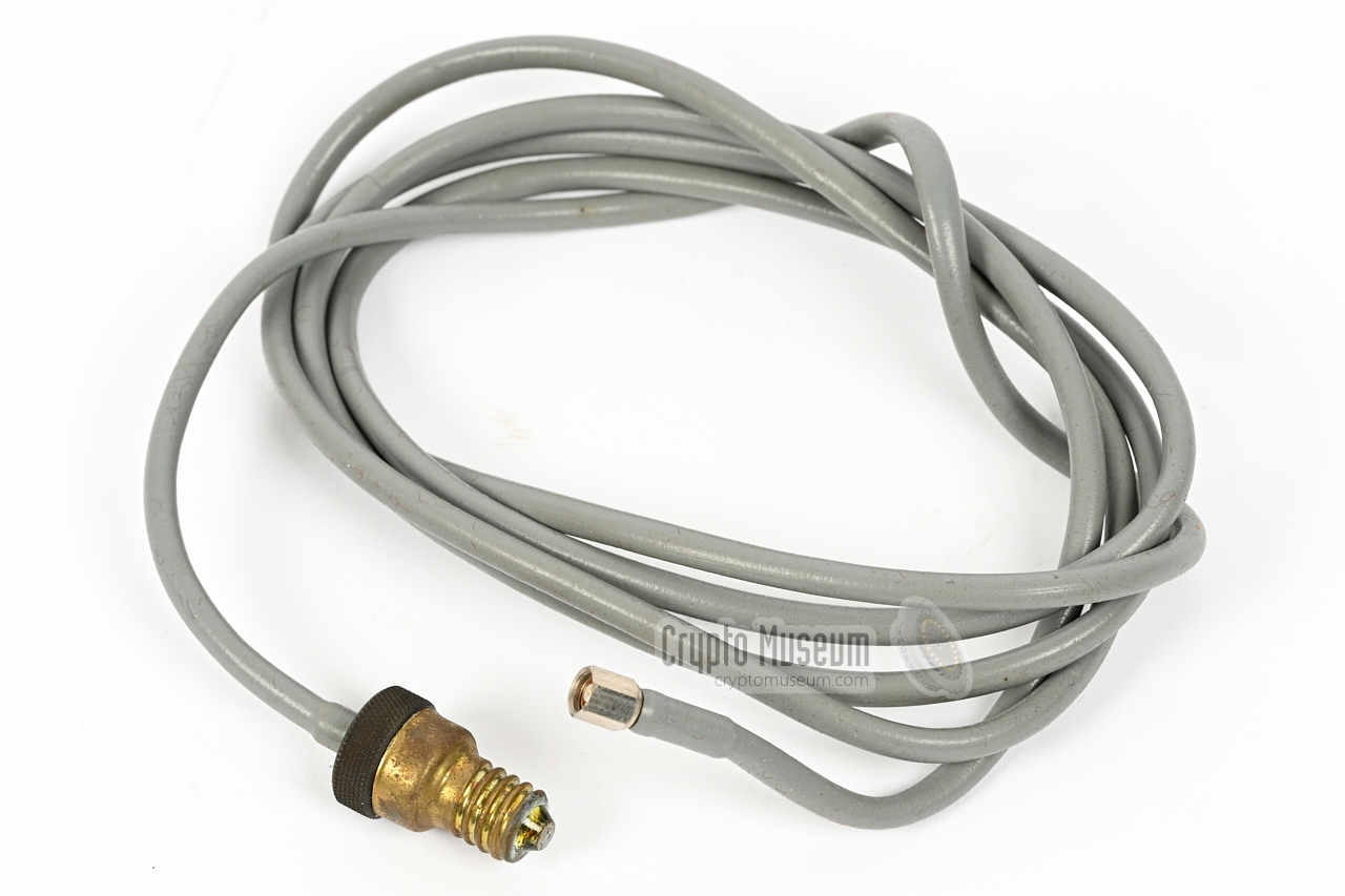
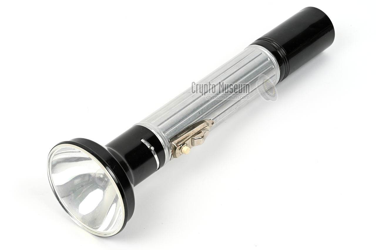
The JO-4.03 can powered by an external 4.5V DC source, that must be connected
to the SMC-socket at the bottom of the handset. In most cases, an
existing portable flashlight was used for this, such as the
Artas Focus shown in the image on the right. It uses three 1.5V D-type
batteries (mono cells) which are sufficient for many hours of uninterrupted
operation.
The reflector must be removed
from the flashlight and the light bulb has to
be taken out of its E10 socket. Next, one end of the
power cable
is screwed into the E10 socket.
|
|
|
|
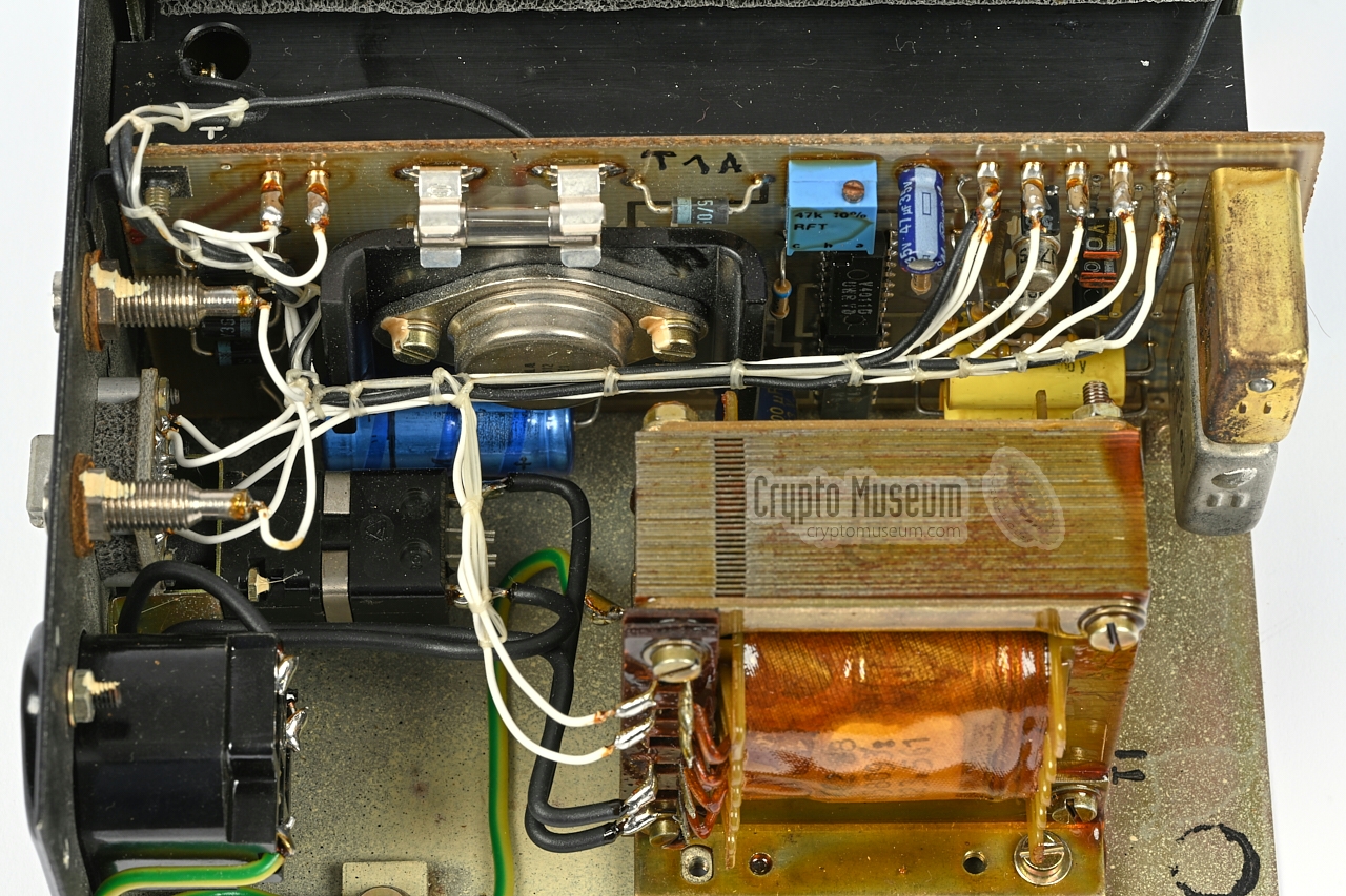
Due to the compact and sensitive nature of the optical parts,
we have decided not to open the transceiver. As the unit is fully
operational, there is currently no need to disassemble it. Below are
several images of device 3 (expansion unit) and device 4 (PSU) that were
taken during their repair.
|
When we obtained a complete set of two
JO-4.03 devices in November 2021, they were both in working condition,
with the exception of the power supply unit (4) and the expansion unit (3).
In both devices the internal fuse holder was corroded to the point where it
no longer conducted.
After replacing the silver-plated fuse holders, the devices were tested and
no further anomalies were found. Nevertheless we replaced all electrolytic
capacitors as a precaution.
Surprisingly, the soft polystyrene foam inside the suitcase
was still in very good condition, which is not trivial after so many years
of storage.
Testing of the two transceivers is possible by setting them up with the
secondary mirror collapsed (i.e. not raised) at a distance of 2 metres. This is
equivalent to a distance of 2000 metres with
the mirrors in place. Everything worked as expected. Apart from a little
background noise, the audio quality and the speech legibility
is excellent.
|
- Units superficially cleaned
- Leather case treated with leather grease
- Expansion unit (3) internal fuse holder replaced
- PSU (4) internal fuse holder replaced
- PSU (4) all electrolytic capacitors replaced
- Battery cable correct (polarity was reversed)
|
|
In this video, German collector Karsten Hansky shows how the 16 kHz
pilot tone from transmitter (1) can be used to activate a
recorder, by connecting the expansion unit (3). This is described
in the advanced setup. Note the 1 kHz confirmation tone
that is returned by transmitter (2) as long as the recording runs.
This way, the agent knows that the message is being received.
After 30 seconds, the recording (and the 1 kHz tone) is stopped automatically.
When the pilot tone is lost, transmitter (2) sends
an intermittent tone for 30 seconds, so that the agent is informed of this.
|
For connection of the DC power, a rectangular 6-pin receptacle
is available on the power supply unit (PSU). Only the outer 4 contacts are
used and they are cross-wired, to that the cable can be inserted either
way. Below is the pinout when looking into the receptacle on the PSU
(device 4).
|
|
At the bottom of the handset is a 5-pin 180° DIN socket on which all audio signals are available.
Below is the pinout when looking into the socket.
|
- Line in (from tape recorder)
- Ground
- Line out (to tape recorder)
- Microphone in (2kΩ)
- Earphone out
|
|
For playing back a pre-recorded message via the local transmitter,
the tape recorder must be connected to the DIN 5/180 socket on the
expansion box (3). That is the socket that is marked with an input symbol.
A suitable cable was supplied with the JO-4.03.
It has a DIN 5/180 plug at one end that that must be fitted to the
DIN 5/180 socket on the expansion box (3).
At the other end of the cable are two further DIN connectors: a 3-pin one
that carries the audio signal and should be connected to the audio output
of the tape recorder, and a DIN 5/360 that carries the signal for starting
the playback. It is currently unclear for what type of tape recorder this
cable was intended, as the standard issue UHER 4000
does not have a socket for the latter.
➤ More about DIN connectors and standard wiring
|
For recording a received message, the tape recorder must be connected
to the DIN 6/240 socket
on the expansion box (3). That is the socket that
is marked with an output symbol.
A suitable cable was supplied with the JO-4.03.
It has a DIN 6/240 plug at one end that that must be fitted to the
DIN 6/240 socket
on the expansion box (3).
A possible wiring layout is shown here.
At the other end of the cable are two further DIN connectors: a 3-pin one
that carries the audio signal and should be connected to the audio output
of the tape recorder, and a DIN 5/360 that carries the signal for starting
the playback. It is currently unclear for what type of tape recorder this
cable was intended, as the standard issue UHER 4000
does not have a socket for the latter.
➤ More about DIN connectors and standard wiring
|
With some units, an external volume control unit was supplied. It is
used to adjust the audio level into the tape recorder. It is currently
unclear how this cable was used, but it is likely that the DIN 5/180 plug
at the left was connected to the 5-pin DIN socket on the handset of the
JO-4.03.
|
Device Line-of-sight (LOS) light-based communication device (Lichtsprechgerät) Purpose Covert cross-border agent communication
Speech, recorded audio, wideband data (7-70 kHz) Usage Indoor (limited outdoor usage) Model JO-4.03 Name Kleine Dahme Designator 17305-1 Manufacturer Carl Zeiss Jena Year 1987 User MfS (Stasi) Frequency 317 THz (940 nm) - infrared Range ≤ 3 km Automatic ≤ 2 km Microphone 250 - 6000 Hz, 0.25 mW into 5 kΩ Earpiece 250 - 3200 Hz Input 150 Hz - 16 kHz, 0.2 - 2V into 10 kΩ (from tape recorder) Output 700 mW into 10 kΩ Data 7 - 70 kHz, 700 mV into 300Ω Power 3 x 1.5V AA-size (in handset)
Mains 220V AC+ (by connecting device 4 PSU)
Battery pack (inside device 4 PSU) Temperature -0°C to 45°C (device 3 and 4)
|
Power 3.5 - 4.5V DC Current 25 mA (RX), 120 mA (TX) Angle (2ω) 0.14° Viewfinder Γ = 5.5x, viewingle angle (2ω) = 7° Temperature -20°C to +45°C (0°C to 45°C for device 3 and 4) Dimensions 170 x 120 x 50 mm Weight 1452 g
|
- Optical transceiver (remote station)
- Optical transceiver (location station)
- Expansion unit
- Power supply unit
|
- Suitcase
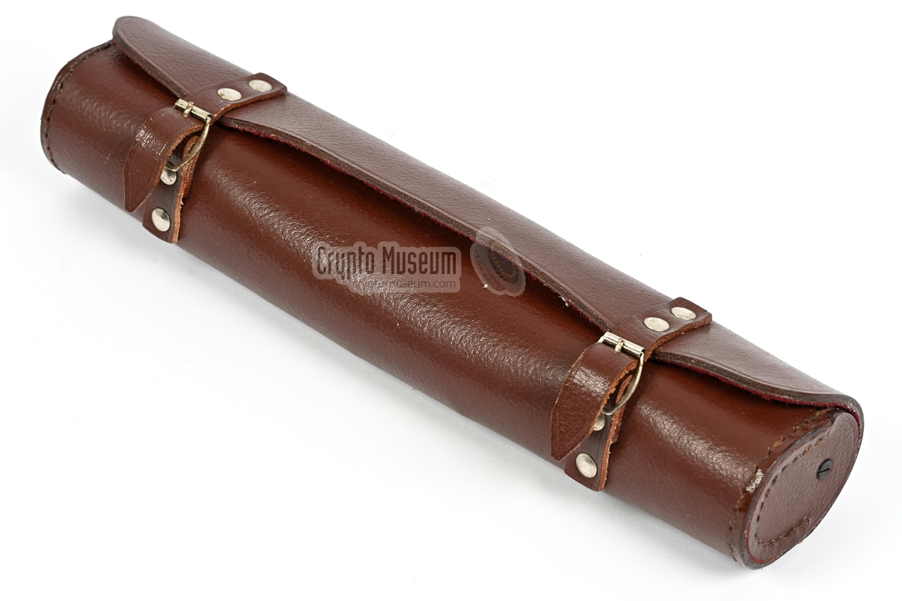
- 45° Periscope in leather wallet
- 2 x Control unit (for 1 and 2)
- 6-pin DIN cable
- Mains cable
- Battery cable with large crocodile clips
|
|
The device is known by the following designators:
|
- JO-4.03
- 17305-1
- Kleine Dahme
- Palme
- Lichtsprechgerät
|
The serial number of a JO-4.03 consists of three digits, prefixed with the
number of the device. For example: if the serial number is 302, the
primary transceiver has the serial number 1 302, the secondary transceiver
has 2 302, the expansion unit has 3 302 and the PSU has 4 302.
Below is a non-exhaustive list of surviving serial numbers:
|
1 224 2 238 3 453 4 536 Private Collector, Germany 1 228 2 216 ? ? Mike Prichard Collection, Australia 1 302 2 302 3 302 4 302 Crypto Museum, Netherlands 1 316 2 316 3 316 4 316 Private collector, Austria 1 425 2 425 3 425 4 425 Private collector, Netherlands 1 225 2 240 3 455 4 550 Private collector, Germany
|
-
Document obtained from BStU [2] and kindly supplied
by Detlev Vreisleben [1].
|
-
Full name: Bundesbeauftragte für die Unterlagen des Staatssicherheitsdienstes
der ehemaligen Deutschen Demokratischen Republik
(DDR) —
Federal Commissioner for the Records of the
State Security Service
of the former German Democratic Republic (GDR) —
officially abbreviated to BStU.
-
Document obtained from BStU [2] and kindly supplied
by Detlev Vreisleben [1].
|
|