|
|
|
|
|

|
Short-range agent communications
The UHER SCRAC 1 was a device for Short-Range Agent Communications
(SRAC),
developed in the early 1960s in
Czechoslovakia, probably by
Správa 6 2 for use by the
secret state police (StB)
and the secret intelligence service Správa 1 3 (espionage).
The device was used by agents and spies for delivering a recorded (verbal)
message to a nearby Electronic Dead Letter Box (EDLB).
|
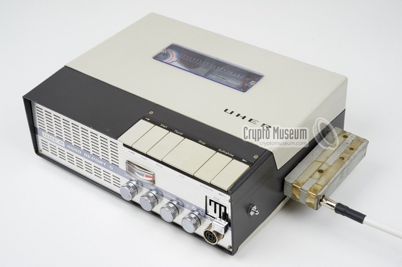
The device was used in combination with an
UHER Report 4000
tape recorder from the early 1960s.
The agent recorded his message verbally on the tape
at the lowest speed (2.4 cm/s). He then placed his UHER recorder in
his car and installed the SRAC onto the
sockets at the right.
He also connected the car radio antenna to it.
Next, he would drive his car to the agreed drop zone and, whilst driving
in that area, play back the message at the highest speed (19 cm/s).
The SRAC shown on the right is in fact a transmitter
that operates in the 88-108 MHz FM radio band.
|
|
|
A receiver, hidden in the drop zone, would pick-up the broadcast and
record it at the highest speed.
It could be placed in another car, in which case the handler
might also be driving around in that area,
or it could be placed in a fixed (unmanned) position,
in which case it was a so-called Automatic Dead Letter Box.
The handler would then collect the recorded message(s) later.
|
The two DIN connectors at one of the long sides of the device are placed
in such a way that they mate with
the outer two DIN sockets at the
right side
of the UHER Report 4000 recorder.
The device gets audio from
one of these connectors, whilst the other one connects the transmitter to
7.5V DC from the recorder's internal batteries.
The image on the right shows the SRAC installed to the right side of
an UHER Report 4000 and connected to the car antenna, ready for use.
The clandestine transmitter will be activated as soon as the play button of
the recorder is pressed.
|
|
|
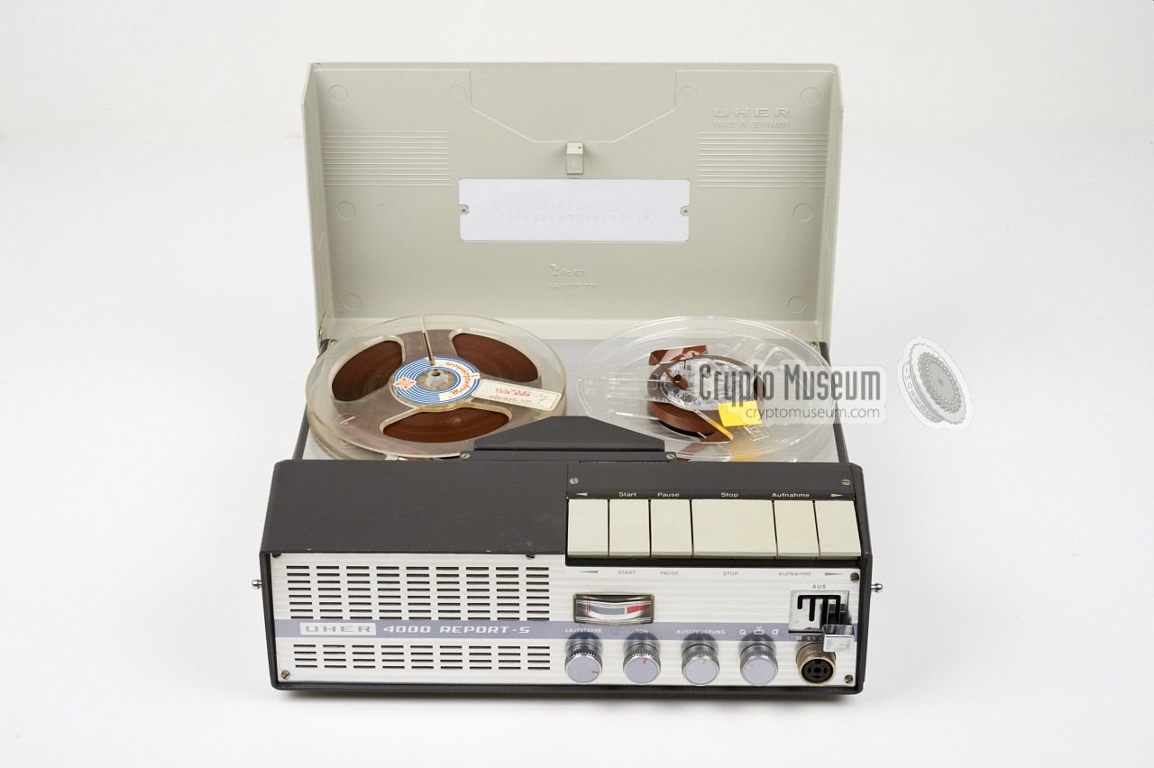
Selecting the UHER Report 4000 for this purpose was a clever move.
It was available off-the-shelf from every good HiFi store, and could
be bought without attracting any attention.
Furthermore, walking around with an UHER recorder
in a European city would be considered normal, whereas
a similar device from an East European manufacturer would certainly have
raised eyebrows.
|
Briefly transmitting a secret message via the FM broadcast band would not
attract much attention in the early 1960s as the 88-108 MHz band was rather
empty in those days (in particular when compared to the situation in 2015).
As the segment above 100 MHz was unused in most West Europen countries,
it wouldn't cause any interference with legal broadcast stations either.
As the transmisson was relatively short and the target was moving,
interception would have been unlikely and
triangulation by means of
Radio Direction Finding (RDF)
would not be effective.
|
|
|
In practice, the selected frequencies were often very close to existing
radio stations, so that they would not be noticed by the radio monitoring
services of the guest country. In theory, the transmission could be picked
up accidently by someone tuning in to a regular broadcast station,
but given the low power and the limited range of the device,
this was not considered a problem.
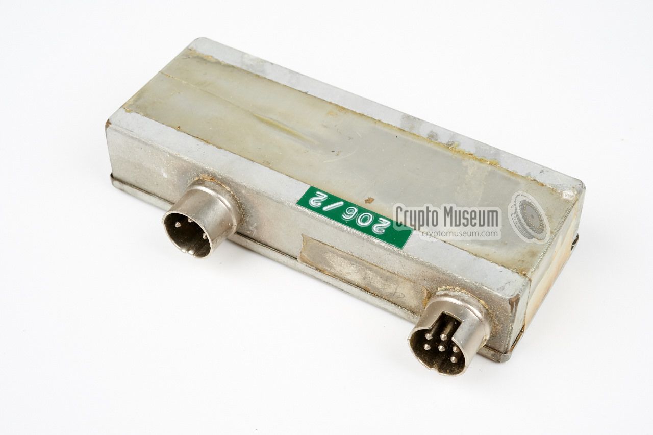
The device shown in the image above is labelled 206/2 and came from a
batch of similar units that were numered consecutively from 206/1 to 206/9.
Apparently these units were each tuned to a different frequency in the FM-band.
It is unknown how many units were built, but it must have been
substantial, as they were used in all countries where
Czechosovakia had a presence.
|
 |
-
UHER SRAC is most likely not the name of this device, but the actual name
is currently unknown. Since the device was designed for short-range agent
communications (SRAC) and because it is used in combination with the
UHER Report tape recorder,
we have given it this nickname.
-
Správa 6 refers to Government Department 6: Communication Technics.
-
Správa 1 refers to Government Department 1: Intelligence (espionage).
|
|
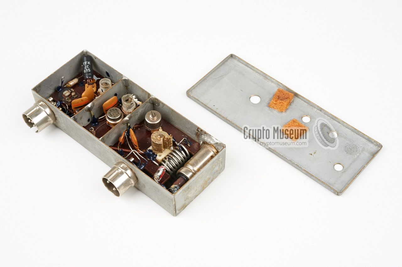
The UHER SRAC is in fact a low-power miniature FM transmitter, housed in a
metal enclosure that measures just 10 x 4 x 2 cm (without the connectors).
It has one socket for the car radio antenna and two fixed connectors
that mate with the outer two DIN sockets at the right side of the UHER
Report 4000 tape recorder. Via these two connectors, the transmitter
receives power and audio.
|
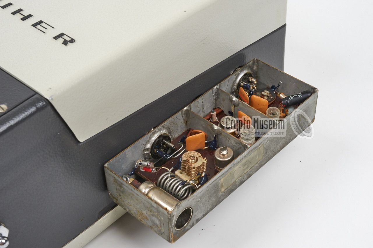
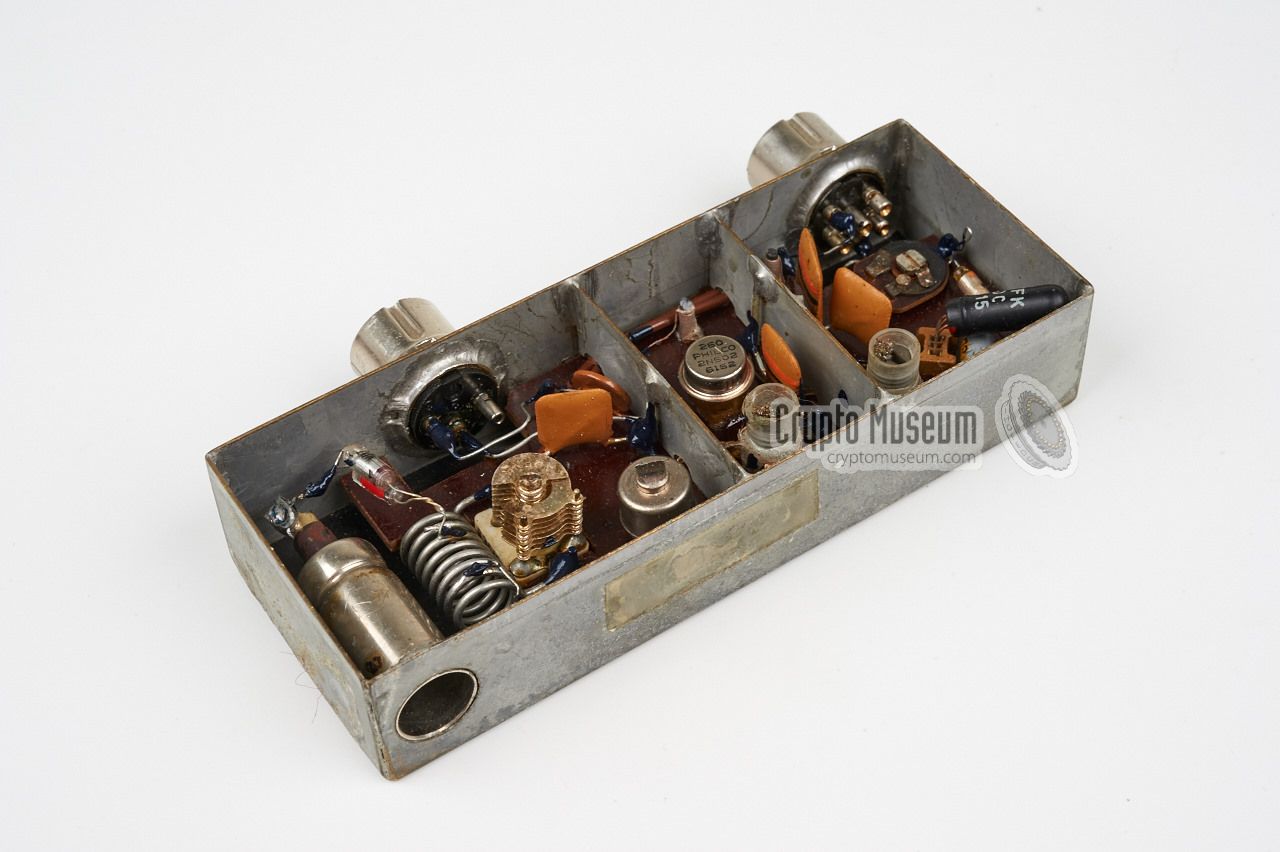
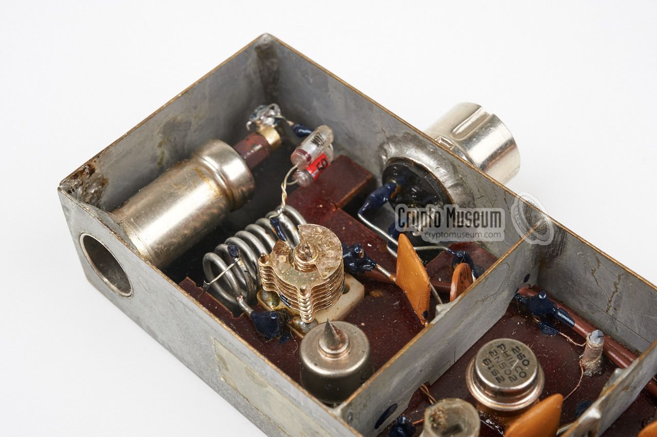
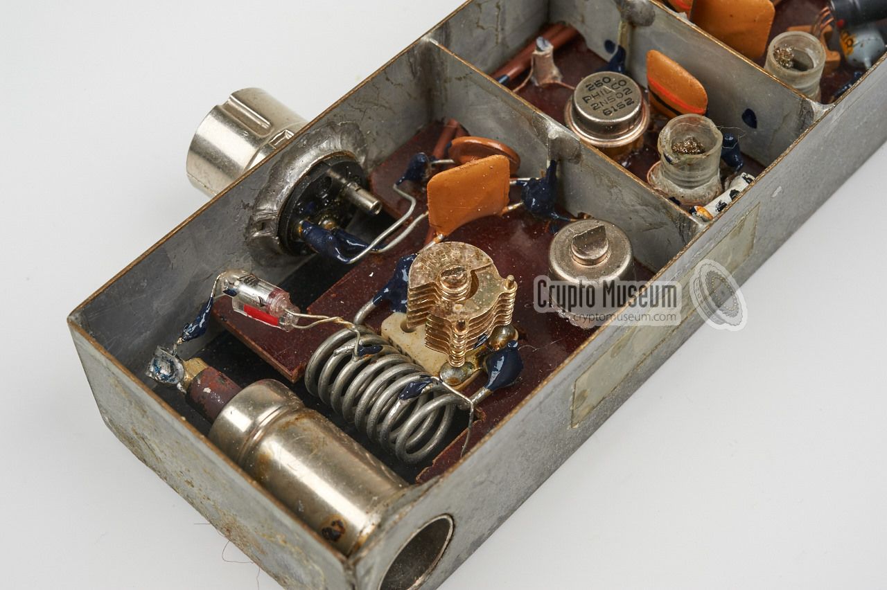
The design of the transmitter is simple, yet very effective. Inside the metal
enclosure are three compartments: the oscillator (left), a driver stage
(center) and a Power Amplifier, or PA, (right).
The oscillator is free-running, and also acts as the modulator by applying
line-level audio from the UHER directly to it.
Using a free-running oscillator instead of a crystal-based one
should not be considered a problem as the transmitter is properly shielded
and most domestic receivers in the FM broadcast band generally have an
Automatic Frequency Correction (AFC) anyway.
|
|
|
The transmitter does not need a separate power source as it is powered
directly from the charge socket on the UHER recorder to which it is connected.
Note the gap in the 6-pin DIN connector on the SRAC. This prevents the
batteries from being disconnected when the connector is inserted into the socket,
as is normally the case when an external battery charger is plugged in.
Considering its age, the transmitter is well-built, using only first class
components. Frequency alignment is possible by adjusting the coils and the
output trimmer through the three holes in the lid of the case.
Note that the transistors used in the device are made by
Western manufacturers like Telefunken
and Philco. The trimmer that is used for the frequency adjustment,
is from Tesla.
|
|
The UHER SRAC has three connections. The antenna socket accepts the coaxial
connector from a standard car radio antenna. The other two are male DIN connectors
that are soldered to the transmitter's frame. They mate with the outer two DIN
sockets at the right side of the recorder.
The pinout of these sockets is as follows:
|
|
This is the (mono) phone/radio socket of the UHER recorder.
It carries both input and output signals at line-level,
but for this application we only need the
recorder's audio output on pin 3.
|
|
Only two wires are needed on this socket.
Note that, like the UHER recorder,
the SRAC has the (+) terminal of the battery connected to the chassis.
This means that the circuit is powered by -7.5V.
|
- -
- -
- Ground (7.5V battery +)
- -
- Power (7.5V battery -)
- -
|
|
|
|
|
Any links shown in red are currently unavailable.
If you like the information on this website, why not make a donation?
© Crypto Museum. Created: Friday 07 August 2015. Last changed: Wednesday, 17 January 2018 - 17:54 CET.
|
|

|
|
|


