|
|
|
|
|

|
|
Stasi Pentacon GSK
GSK automatic control unit
The GSK Controller (German: GSK Steuergerät) is a compact remote control unit
for the GSK low-noise surveillance camera, used by the security
service of the former DDR (East-Germany) – MfS, or Stasi. The device
allows manual as well as automatic operation and allows photographs to be
taken at configurable intervals.
The manufactuer and the production quantity are unknown. 1
|
It is known however that they were not suppied with every GSK, and that
the GSK cameras that did come with the automatic controller, had a dot behind
their serial number (e.g. 6877·). The same number was present on the
controller.
The device can read the value of the camera's built-in light meter and can also
be used to alter the exposure time in 10 step (plus automatic). In addition, it
can be used to take pictures automatically at configurable intervals.
Buttons are present to take a single picture or a series of pictures, but
this can also be done remotely.
|
|
|
|
When the 17 m film cartridge is used (for 450 exposures),
its operation is monitored by a white indicator lamp at the front panel,
marked 17m - KASSETTE. A blinking lamp indicates normal operation. The device
must be powered by an external 9V DC source, such as the battery pack
or the mains power supply unit (PSU).
In this configuration, the camera is powered by the controller.
|
-
There is no indication of a manufacturer or model number on or inside the
device. The serial number at the front panel (6079 in this case),
suggests that it was probably supplied with the GSK camera
with serial number 6079· (note the dot behind the serial number which
indicates the presence of the controller).
|
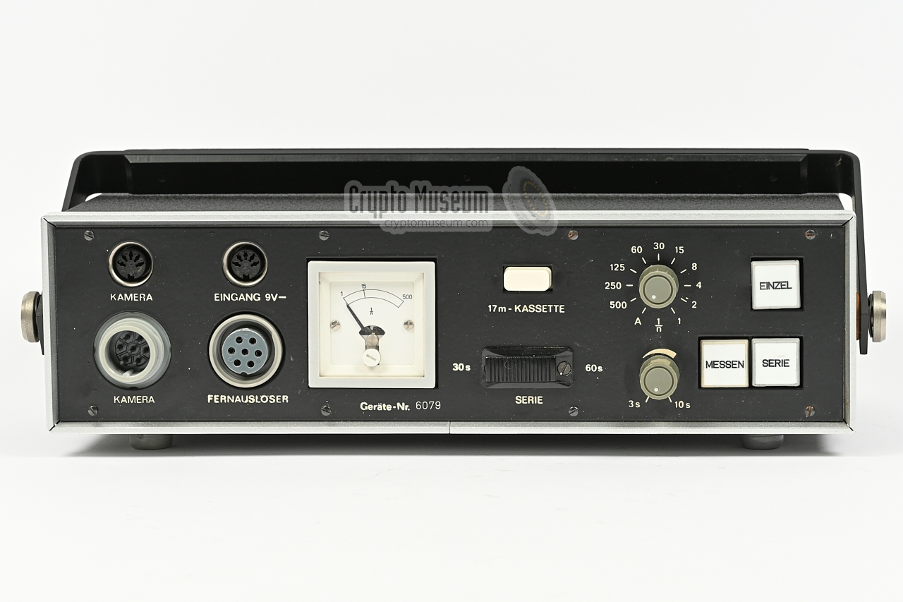
All controls and connections are located at the front panel of the device,
as shown in the image below. At the top left are two power sockets: one for
the 9V DC input from the external PSU, and one that supplies 9V DC
to the camera.
Note that the latter needs a fully populated cable,
as it also carries the film-end signal from the (optional) film cartridge
to the 17m indicator lamp.
At the bottom left are two RFT NS receptacles. The leftmost one (NS105)
must be connected to the camera using a
fully populated male/female cable.
To its right is an NS104 sockeet, that can be used to connected the
manual controller or another external device that triggers exposure.
At the far right are three push-buttons for taking a single photograph (EINZEL),
a series of photographs (SERIE) or for measuring the level of the camera's
internal trough-the-lens (TTL) light meter (MESSEN). The remaining controls are
for setting the shutter speed (1/n) and for setting the interval time (3-10s)
and duration (30 or 60s) when taking a series of photographs.
|
The diagram below shows how the automatic controller is integrated with the
rest of the GSK camera system.
At the centre (yellow) is the controller,
which is powered by the mains PSU or by the battery pack.
At the left is the GSK camera, which is connected to the
controller via 2 cables: a 5-pin DIN cable for power distribution and
a 7-pin RFT NS104/105 cable for remote control.
When the optional 17 metre film cartridge
is connected to the GSK,
its optical en-of-film detector will cause the indicator light at the front
panel of the controller to light up continuously when the end of the film is
reached. During normal operation, the lamp blinks when taking pictures.
|
|
|
Manual controller
899 006
|
|
|
When taking pictures manually, the exposure button shown in the
image on the right can be connected directly to the camera. Each time
the red button is pressed, an image will be taken.
The device can also be connected to the socket marked FERNAUSLÖSER
at the front panel of the automatic controller,
in which case the grey knobs can be used to shoot a series
of pictures.
➤ Wiring details
|
|
|
|
|
Power supply unit
899 005
|
|
|
The camera must be powered external by 9V DC source,
such as a battery pack or the mains PSU shown
in the image on the right, either directly or via the automatic controller.
A simple 1:1 DIN 5-pin male/male cable can be used to connect the PSU
to the camera or to the controller. In the latter case, an additional
power cable must connect the controller to the camera.
➤ Wiring details
|
|
|
For situations where no mains power is available, the controller
can be powered by the external battery pack shown
in the image on the right.
The case accepts six D-size battery cells of 1.5V each, that are series
connected to provide the 9V for the controller and the camera.
Move over the image to look inside.
➤ Wiring details
|
|
|
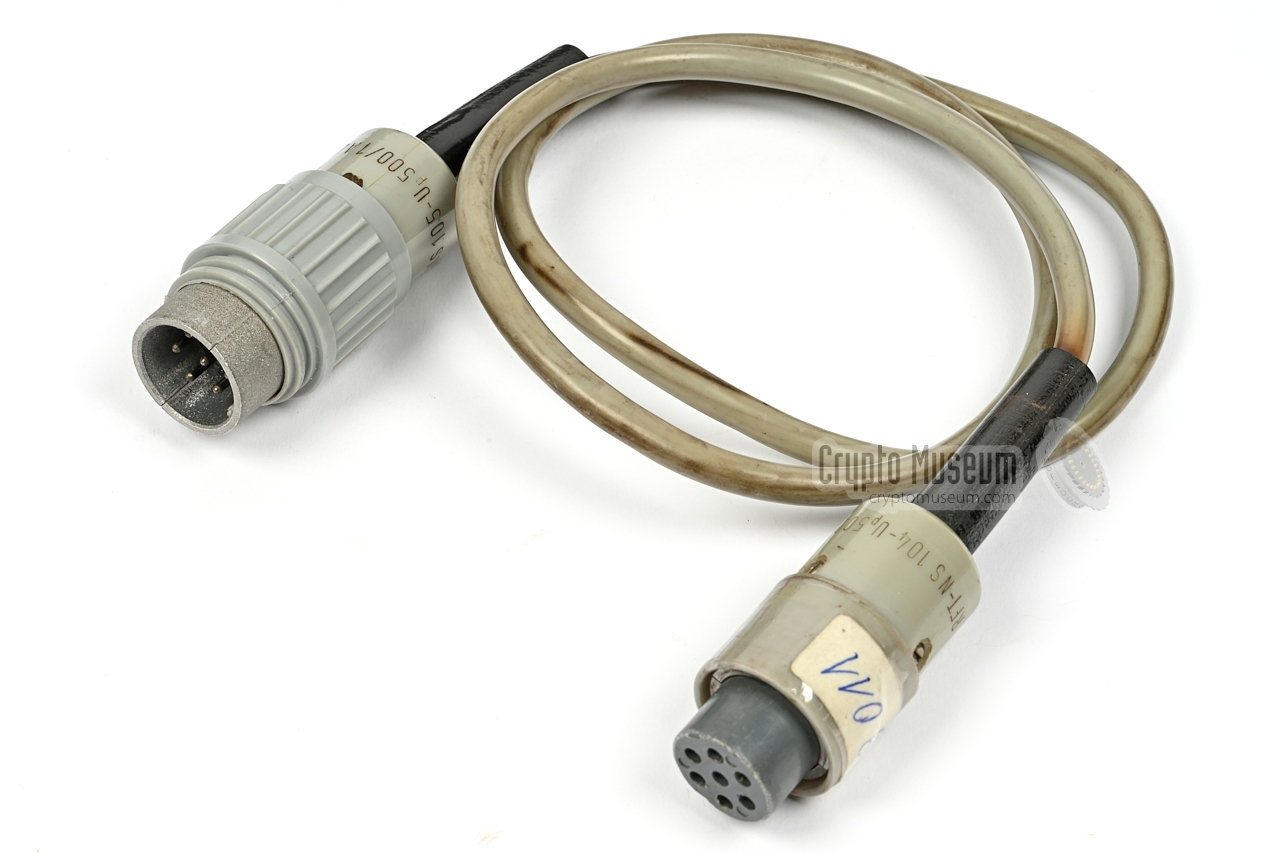
The image on the right shows the short version of the interconnection cable
that is needed to connect the control unit to the GSK camera. It is a
7-pin male/female cable with RFT NS104 and NS105 cable parts.
A longer version of the cable was available for situations in which the
automatic control unit could not be placed in the vicinity of the camera.
➤ Wiring details
|
|
|
Power is distributed between the various parts of the SR-899 (GSK)
system by means of 5-pin DIN 180° male/male cables of various length. The image
on the right shows the short version.
Note that only three pins of the 5-pin connector are used, and that a 2-wire
cable is sufficient for power distribution.
➤ Wiring details
|
|
|
Below is the circuit diagram of the device as taken down at Crypto Museum
in December 2021. Note that this is significantly different from the
circuit diagram held in the archives [B],
which is probably from an earlier – less advanced – version.
The circuit is built around four MCC102 ICs (threshold switch) [a]
that were developed especially for use in
cameras. It is compatible with the later A302D (developed in the DDR) and
the later TCA345A [b].
The circuit will only draw current whenever a button is pressed
or a function is currently active.
D3 (SAM45) is a diode array.
It controls the 9V power and enables reed relay Y1, using signals from
various places in the circuit.
The push-buttons at the front panel have the following functions:
S1 = Single exposure, S2 =
Series exposure, S3 = Measure (only when S4 is set to auto 'A').
S3 consistst of two momentary switches that are operated
simultaneously. All other front panel controls are shown in red.
As the circuit is spread over three areas – including two PCBs – the
internal contact numbers of the PCB-connectors are shown in the diagram
(A1 - C15). The front panel connectors (B1-4)
are all shown as seen from the front panel of the device.
Note that the rotary selector (S4) is a 3-deck 11-position
switch, that is used to set the exposure time (1/n). In the leftmost position
(counter clockwise) it is set to Automatic (A), in which case
the exposure time is controlled by the camera.
Most of the circuit is located on the larger PCB, including a small reed
relay (Y1) that enables the 9V supply to the rest of the circuit,
whilst the smaller board holds three large reed relays. Each relay
contains two switches. Two relays (Y3 and Y3') are driven in parallel, so that
4 switches (y3a-y3d) are operated simultaneously. Also not that switch y2 is
wired in parallel to switch y3b.
|
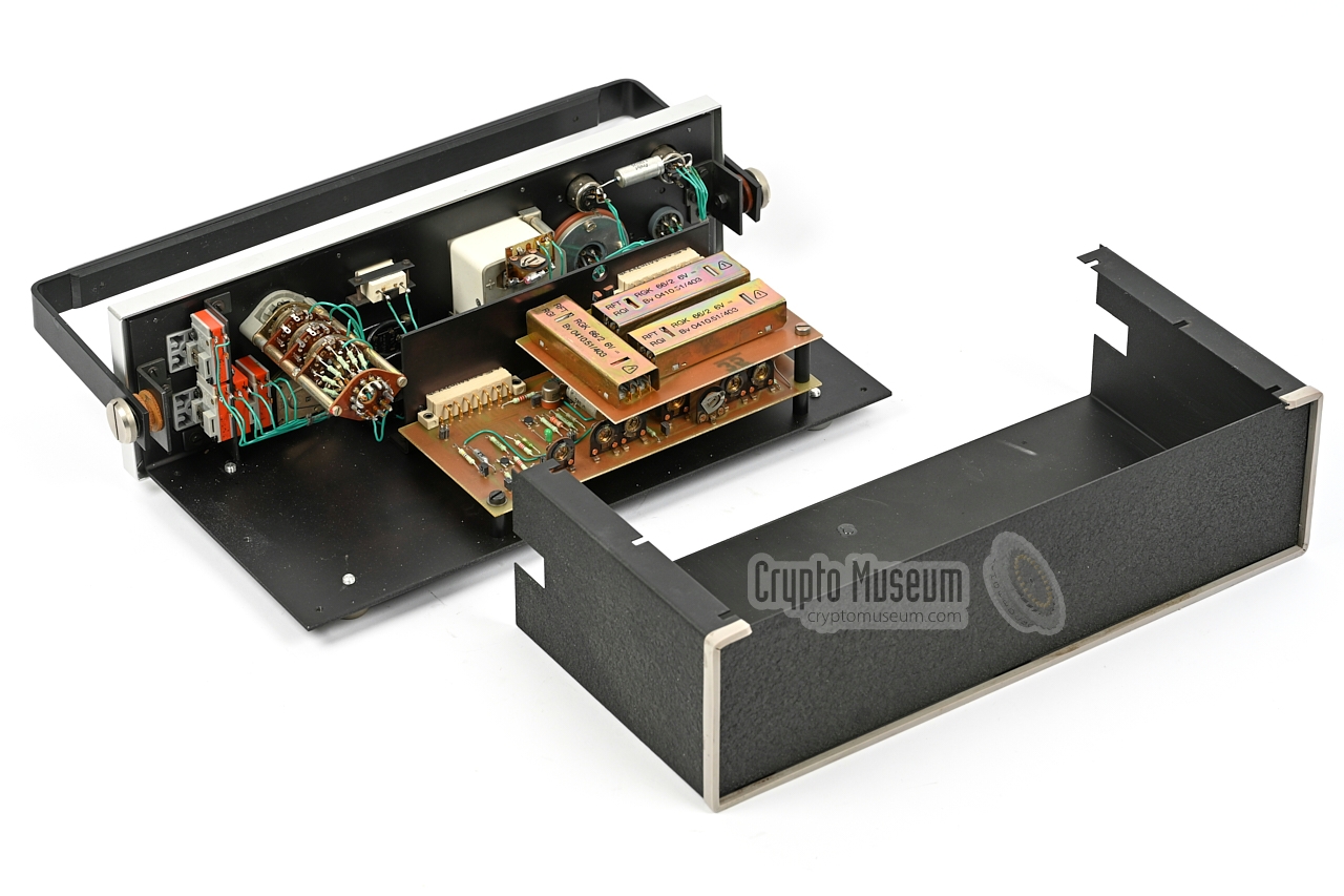
The device is housed an a black wrinkle-painted aluminium enclosure that
measures 335 x 170 x 95 mm and weighs little over 2 kg. The interior can be
accessed by removing six screws at the edlges of the bottom, and sliding
off the case shell. This reveals the interior as shown above.
All controls and connections are fitted to the front panel and are wired
internally. Just behind the front panel is a metal backplace that holds two
printed circuit boards (PCBs): a large one and a smaller one. The large
one holds most of the electronic circuits and is fitted to the backplane by
means of two 15-pin connectors (in the circuit diagram denoted as A and B).
The smaller PCB holds three large reed-relays with two switches each, that seems
to be a bit overdimensioned for the application. The relay board is fitted to
the backplane by means of one 15-pin connector (C).
The mechanical build quility is very good, just like the quality of the
chosen connectors, switches and other parts. The PCB-design however,
is messy and unnecessarily complicated, suggesting that it was made by a
company with good mechanical skills but limited electronic experience.
It is therefore possible – if not likely – that the device was made by
Pentacon and not by, say, RFT.
|
|
The output of the power PSU is available on a 5-pin 180° female DIN connector
at the end of a fixed cable. Below is the pinout when looking into the connector.
This is the same as the pinout of the 5-pin 180° DIN socket at the front of the
controller marked EINGANG 9V—.
Suitable 5-pin DIN male-male cables were supplied with the kit.
|
- 0V (connected to 2)
- 0V (connected to 1)
- n.c.
- +9V DC
- n.c.
|
|
|
The power output is located to the left of the power input socket.
It is marked KAMERA and must be connected to the power socket on the camera.
Note that this cable needs one more wire than the one described above. It
provides a signal (0V) on pin 5 when the film in the the
(optional) 17m film cartridge has reached the end.
Below is the pinout when looking into the socket.
|
- 0V (connected to 2)
- 0V (connected to 1)
- n.c.
- +9V DC
- 17m cartridge end
|
|
|
Like the camera, the automatic controller can also be operated by manually,
by connecting the hand-operated controller to the receptacle marked
FERNAUSLÖSER. This RFT NS104 socket accepts an NS105 plug. Apart from the
manual controller, this socket is also used for connection of external
equipment (remote control) that can trigger an exposure.
|
- Common
- n.c.
- n.c.
- Series exposure (connect to 1)
- n.c.
- n.c.
- Single exposure (connect to 1)
|
|
|
The controller has an NS105 male receptacle – marked KAMERA – at the front
panel. It should be connected to the NS105 female receptacle at the side
of the GSK camera, by means of a short or long
male/female interconnection cable.
Below is the pinout of the male receptacle when looking into the
receptacle.
|
- Single exposure (connected to 7)
- Light meter input (1)
- Light meter input (2)
- +4.5V for light meter (output)
- Shutter open
- Shutter close
- Single exposure (connected to 1)
|
|
-
Document kindly provided by Detlev Vreisleben [1].
-
Document obtained from BStU [2] and kindly supplied
by Detlev Vreisleben [1].
|
|
|
|
Any links shown in red are currently unavailable.
If you like the information on this website, why not make a donation?
© Crypto Museum. Created: Tuesday 16 November 2021. Last changed: Wednesday, 05 November 2025 - 11:41 CET.
|
 |

|
|
|