|
|
|
|
|

|
|
CIA NRP EC
The device is housed in a rectangular metal enclosure that measures
13.5 x 22.5 x 110 mm, and is in fact the high-power variant of the
SRT-90.
It consists of an RF module that operates between
270 and 400 MHz, and a video coder for the
Dirty Pulse (DP) 1
audio masking scheme.
When the SRT-91 was released for field use in June 1974, it marked the
transition from conventional components and manufacturing techniques, to
surface mount devices (SMDs), resulting in a much reduced size and a more
efficient integration of the individual circuits.
|
|
|
The device is powered by a DC source between +2.25V and 3.25V and consumes
typically 800µA, whilst delivering a peak-output-power of 20mW.
A low-power variant of the SRT-91 was made available as the
SRT-90,
which is slightly smaller and consumes 160µA whilst delivering 1mW.
The first concepts of the SRT-91 were delivered to the CIA for evaluation
in March 1970. After several improvements and further miniaturisation,
it finally went into production in June 1974.
➤ More about its history
|
|
According to an intermediate development study of October 1973 [3],
the following models of the SRT-91 existed. Note that these designators are
conflicting with the later frequency scheme
shown below. We therefore assume that the module numbers below
were for internal use only.
|
SRT-91 A 270-400 MHz, DP masking, low-power → later: SRT-90 SRT-91 B 270-400 MHz, DP masking, medium power SRT-91 C L-band version (235-360 MHz) SRT-91 D Binaural version (stereo) — later: SRT-92 SRT-91 E Wideband version (30 kHz audio)
SRT-90 Low-power variant (slightly shorter) SRT-SP Miniature version (development)
|
|
|
Miniature version
Super Pulse
|
|
|
In parallel with the development of the SRT-91, the NRP also worked on
a sub-miniature version of the bug. This project was known under the name
Super Pulse (SP),
but did not result in a new product.
Nevertheless, experience from the Super Pulse project was used to
improve the SRT-91.
➤ More about the Super Pulse project
|
|
The SRT-91 operates on a pre-determined spot frequency between 270 and 400 MHz,
that is factory adjusted. The selected frequency is presented as a suffix to
the transmitter's model number (e.g.: SRT-90-A). The following frequencies
were used (± 5 MHz):
|
- 275 MHz
- 295 MHz
- 315 MHz
- 335 MHz
- 355 MHz
- 375 MHz
- 395 MHz
|
To hide the RF carrier and its modulation from regular
surveillance receivers,
professional bugs often use a special technique
that is known as
audio masking.
The SRT-91 uses a sophisticated masking scheme, based on Pulse Position
Modulation (PPM), known as
Dirty Pulse (DP) masking.
This masking scheme is characterised by an AM carrier with a rather large
bandwidth (~ 7 MHz) and a multitude of sidebands at either side,
caused by the short square-wave pulses.
In addition, the front porch of each pulse is shifted in time, under
control of an internal random noise source.
There are currently no known commercially available
surveillance receivers
or bug tracers
that can readily demodulate a DP-masked
audio signal. Most receivers won't even lock onto the carrier.
➤ More about DP audio masking
|
Along with the SRT-91, a new modular receiver was introduced that was capable
of decoding the new Dirty Pulse (DP) masked audio signals.
It was known as SRR-91, and was just 6 cm high, so that it could easily be
fitted inside a standard executive style Samsonite briefcase of the era.
By installing the decoder module the other way around, the receiver could
also be used for decoding RP-masked bugs, such as the
SRT-56.
➤ More information
|
|
|
|
Signals from the SRT-91 can be received and demodulated with the following
receivers:
|
|
A complete SRT-56 transmitter consists of one or more of the following items:
|
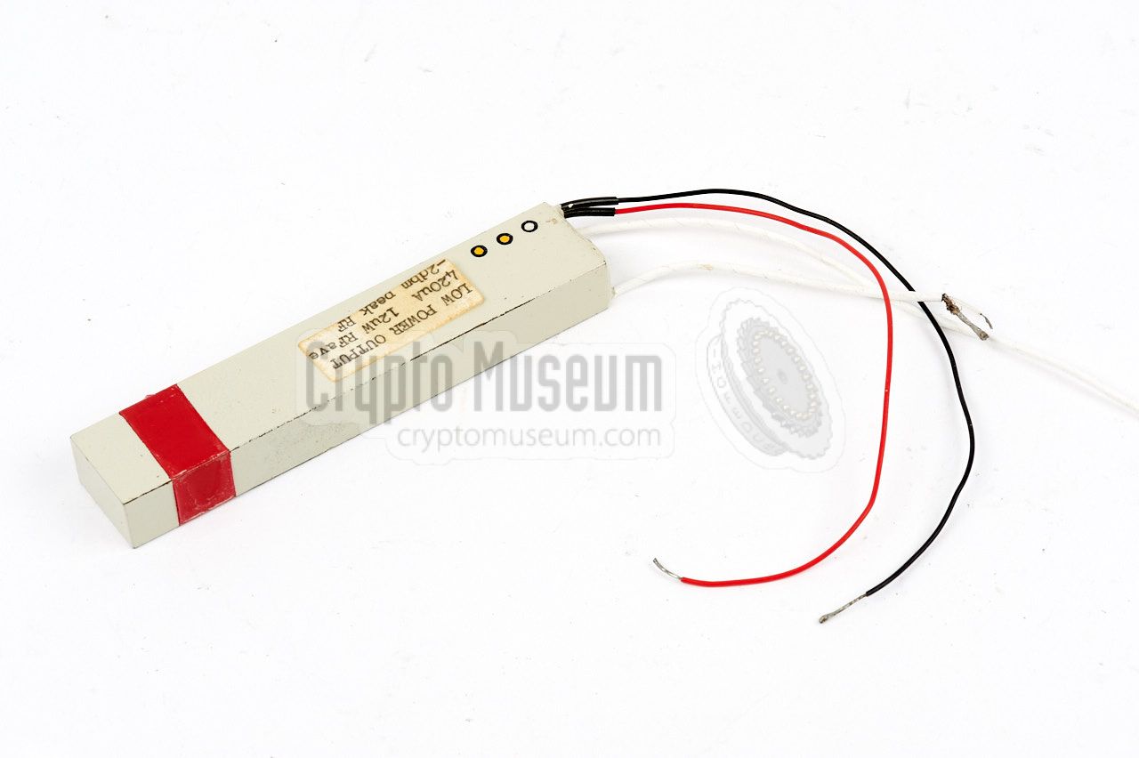
The transmitter is the core part of each bugging system. The SRT-91
measures 110 x 22.5 x 13.5 mm and houses the RF unit (transmitter) as
well as the video encoder (the audio masking unit) in a single enclosure.
As a result, wiring the unit for operation use has become extremely simple.
The red and black wires are used to provide a DC power source between 2.25 and
3.25V, whilst the two white coaxial cables are used for the connection of an
antenna
and a microphone.
|
|
|
Although the SRT-91 can be used with virtually any type of
sensitive dynamic microphone, it was commonly used in combination
with a Knowles BA-1501
or BA-1502 element.
Measuring just 10 x 10 x 5 mm, it was one of the smallest
dynamic microphones available. It has an excellent
dynamic behaviour and a good frequency response
curve, and was commonly used in military equipment for many years.
➤ More information
|
|
|
The SRT-91 was commonly used in combination with a so-called
Sleevex antenna,
which was also developed by the NRP.
Made from a piece of rigid coax cable, Sleevex antennas
were available for a variety of frequency ranges.
Furthermore, different types of Sleevex antennas were available
for embedding in a variety of environments, such as wood and concrete.
➤ More information
|
|
|
Bugs like the SRT-91 were generally used for a limited period of time,
which makes them ideal for battery-powered operation. Due to the fact
that an SRT-91 consumes less than 800µA of current, the transmitter can
work reliably for several months on just two mucury battery cells of
1.35 V each. If a longer life was needed, several mercury cells could be
used in parallel.
If an even longer life was needed, the unit could also be operated from
a dedicated mains power converter.
|
|
|
|
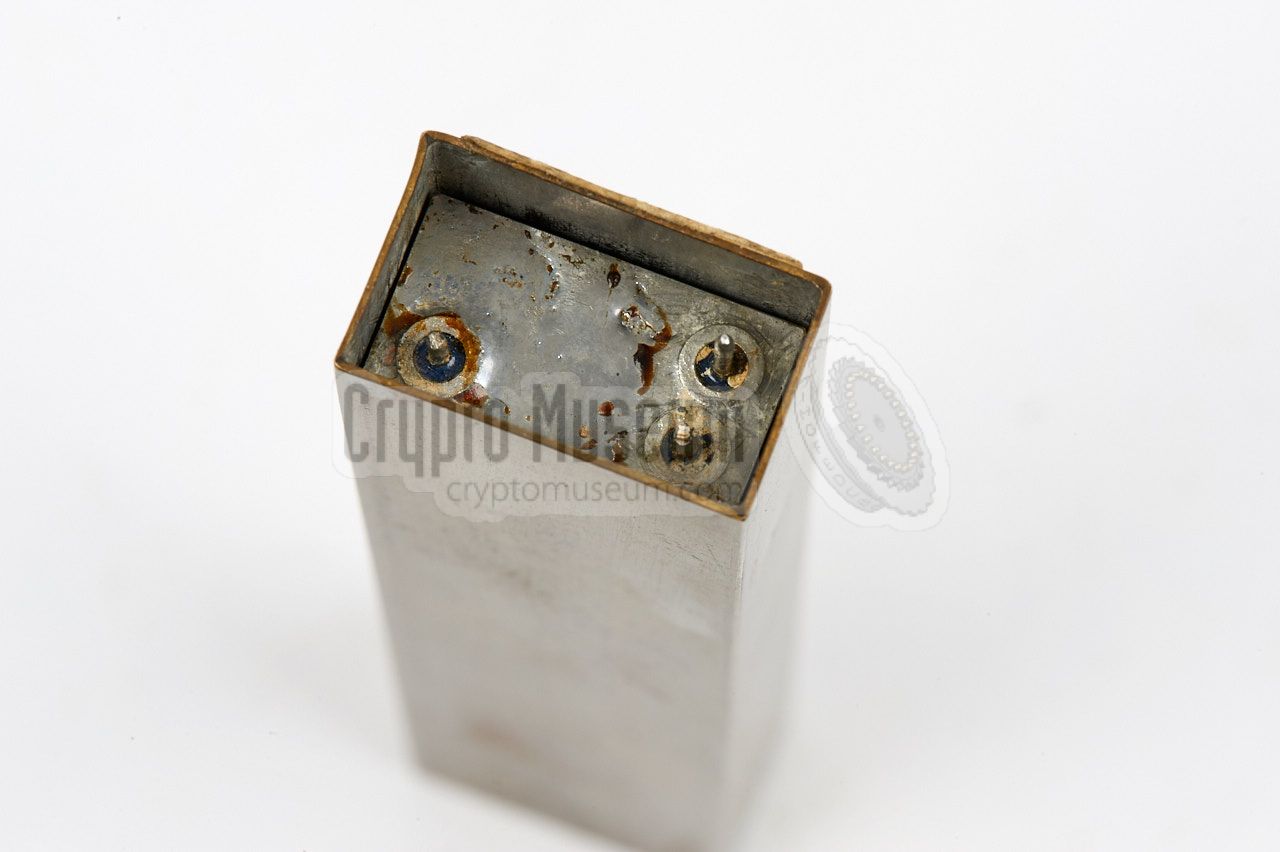
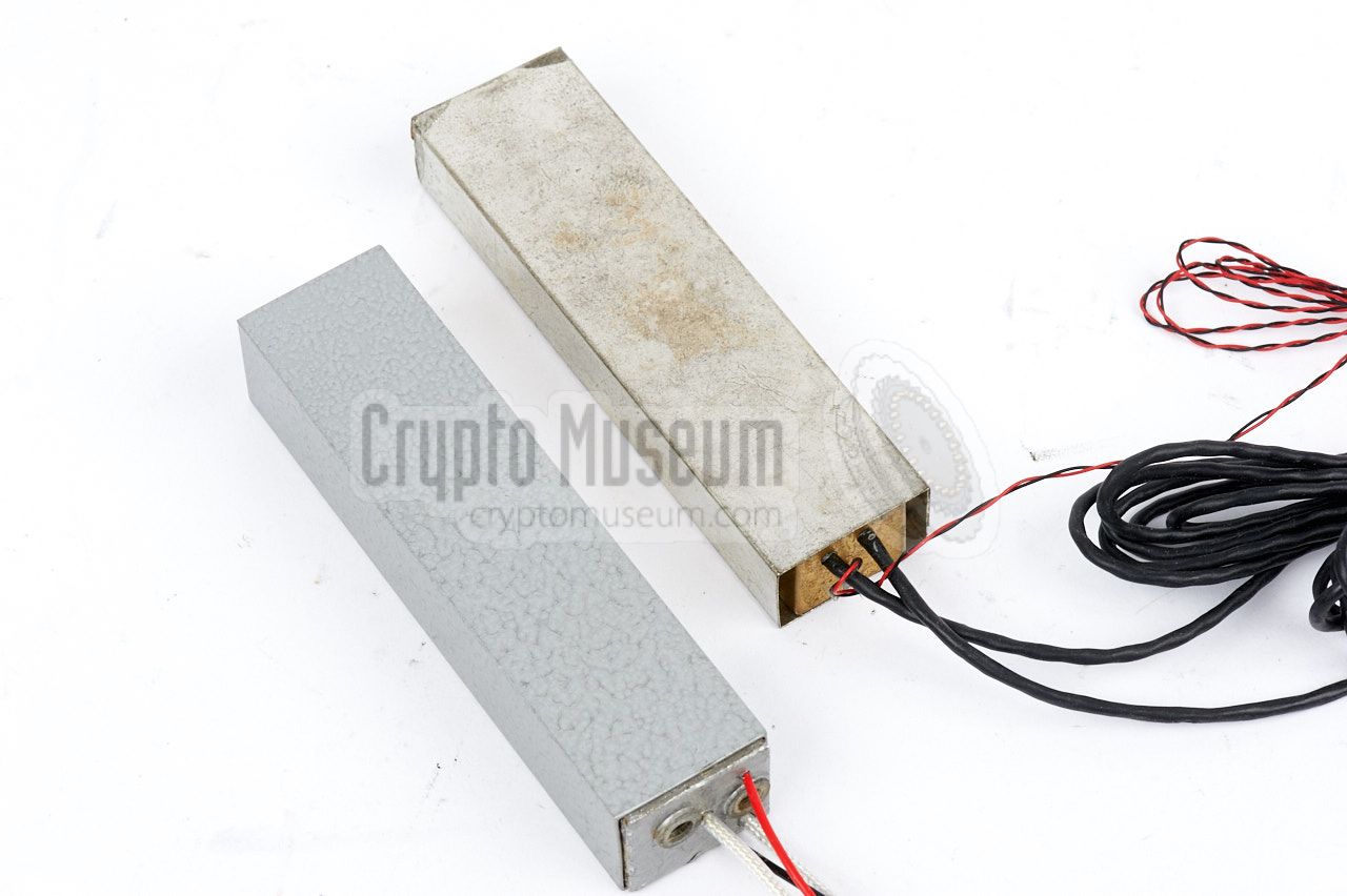
The SRT-91 is housed in a strong brass enclosure that is sealed (soldered)
hermetically. The cable end of the enclosure is then cast in a strong
two-component epoxy, after which the entire unit is sprayed in grey or
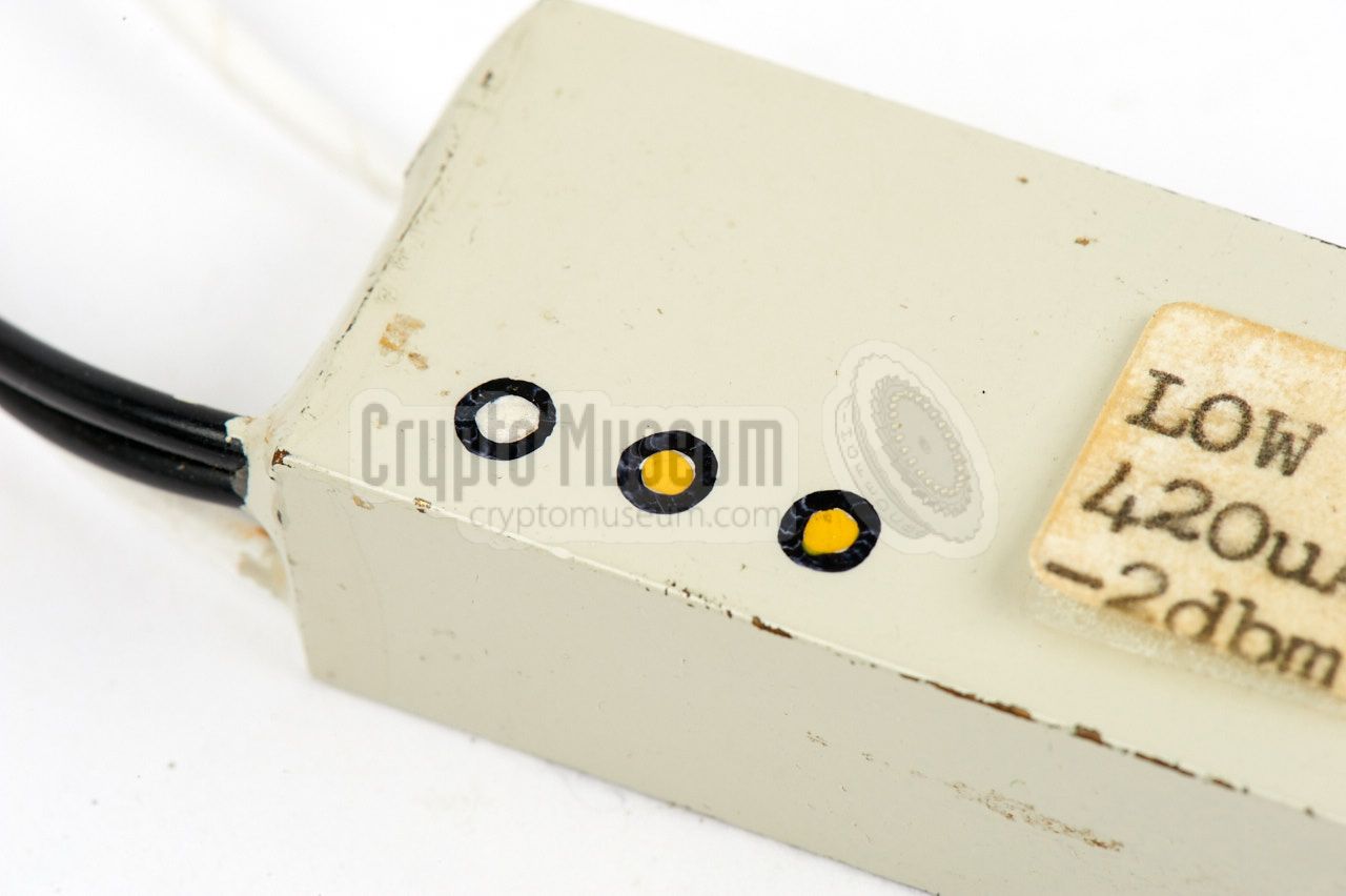
beige. The serial number is present as a series of
three coloured dots.
|
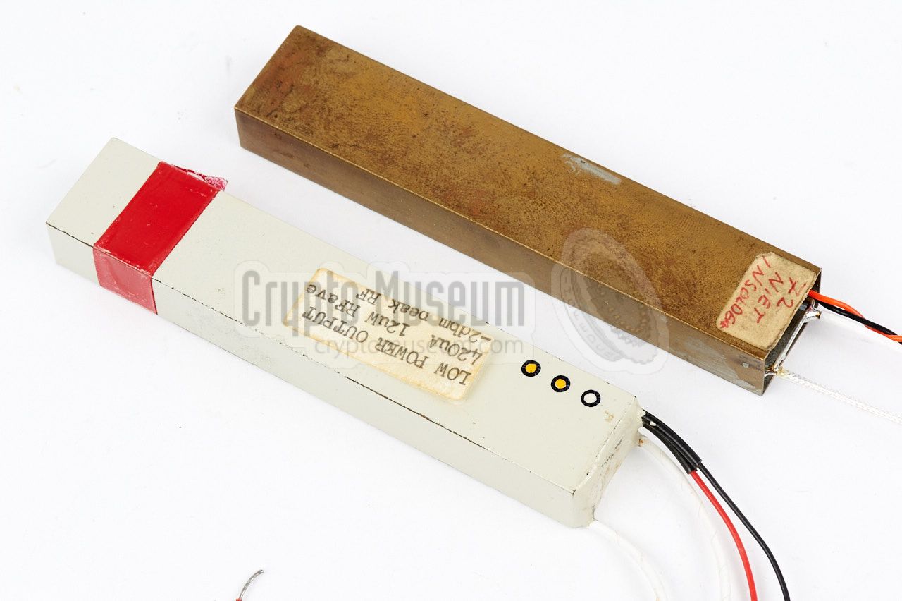
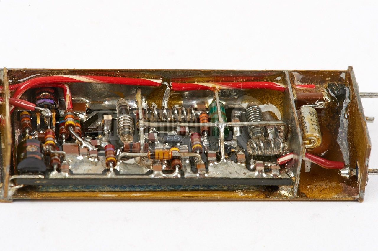
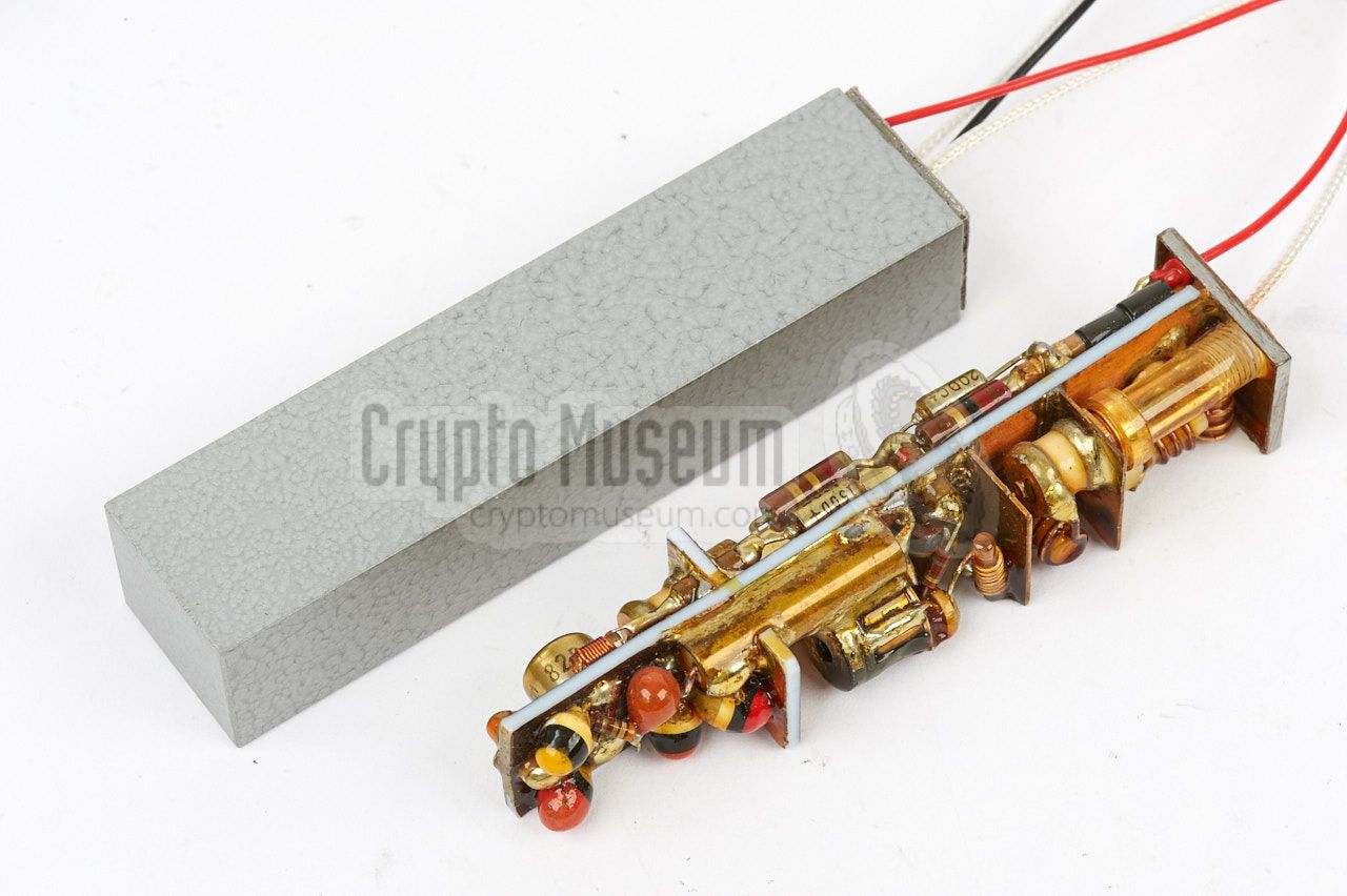
Getting access to the interior of an SRT-91 is very difficult, and is not
possible without badly damaging the unit. Luckily, we were able to obtain the
laboratory model of the transmitter, which was used as an example during
the manufacturing process in the mid-1970s.
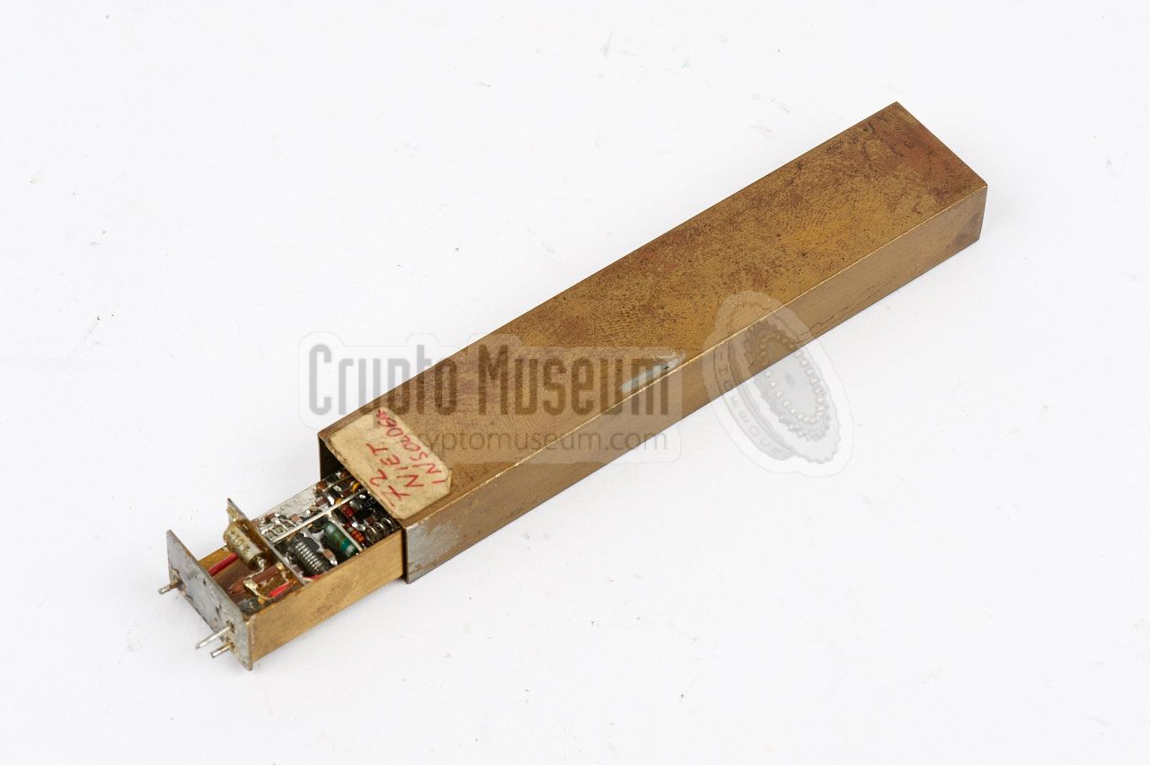
As the model is not soldered and cast in expoxy, the interior can be
extracted from the enclosure
quite easily. The first half of the unit is taken by the
pulse transmitter,
also known as the RF unit, whilst the other half houses the
video encoder.
This part is responsible for the audio masking.
|
|
|
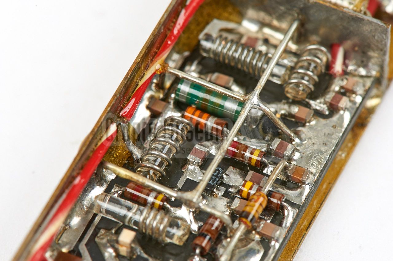
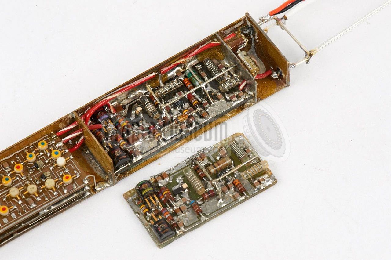
The video encoder consists of
three stacked PCBs that are populated with
the first generation of surface mount components, also known as surface
mount devices (SMDs). The stack consists of a microphone amplifier and
conditioner, a noise generator and the actual DP audio masking unit.
The latter converts the audio signal into a series of short
position-modulated pulses (PPM) that drive the RF unit, using noise
to randomly change the position of the leading edge of each pulse.
|
The block diagram below illustrates the operation of the SRT-91.
At the left are the three stacked PCBs, of which the bottom one contains
the microphone amplifier and the Automatic Gain Control (AGC).
The PCB in the middle contains the random noise generator and the power
regulator.
The upper PCB contains the actual video encoder, which is based on
a 20 kHz master oscillator and a flip-flop (FF), that is set by the
phase of the audio + noise signal, and reset by the phase of
just the audio signal. This results in a series of short pulses
with an average duration of 1µs, spaced 50 µs apart, that are used to
drive the keyer of the 340 MHz pulse transmitter at the right.
|
|
The development of the SRT-91 dates back to 1966, when the first concepts
of its audio masking scheme were tested, based on the Dirty Pulse (DP)
and Super Pulse (SP) developments. The scheme is based on Pulse Position
Modulation (PPM) with a repetition rate of 20 kHz. Masking is obtained
by varying the pulse width randomly, based on the output of a (true)
noise generator.
|
In the earliest implementation, the noise was used to alter the position
of the trailing edge of each pulse, but this was later changed to the leading
edge, so that only the trailing edge of each pulse could be used to
recover the audio.
The first concept prototypes were delivered to the CIA in March 1970,
and consisted of two separate enclosures:
an SRK-43 RF unit,
and an SWE-91 video encoder.
At that time, the bug was still powered at 5.2V, just as previous
bugs like the SRT-56.
This was later lowered to 2.7V,
so that it could be powered by two mercury cells.
|
|
|
After several tests, improvements, new concepts, a lower DC power supply,
simplified wiring and a much smaller enclosure,
the first production units were delivered to the
CIA in June 1974, soon followed by the low-power variant
SRT-90 in 1975.
The SRT-91 was an important product for the
NRP
and the CIA,
as it marked the transition from conventional components to
SMD technology.
The use of SMD parts significantly reduced the size of the transmitter,
especially in comparison with earlier transmitters like the
SRT-56.
In order to reduce the size even further, the CIA also commissioned
other contractors to build pulse-type transmitters based on the
NRP design of the SRT-91. One example of a compatible
pulse transmitter that was made elsewhere is the
SRT-99.
|
|
|
Path loss survey system
URS-1
|
|
|
A bugging system generally consists of a small transmitter with a
low RF power ouput, in order to reduce power consumption and minimise
the change of discovery.
In order to establish the requirements,
the CIA commonly used a path loss survey system, such as the
one shown here, in an environment which resembled the
actual situation at the target area.
➤ More information
|
|
|
- Provisional Technical Manual for SRT-91A
NRP, March 1973. CM302504/A.
- Protype Evaluation of the XSRT-91A Pulse Position Modulated Transmitter
CIA, project 74-1032. Date unknown, but probably June 1973.
CM302504/B. 9 pages.
- Provisional Technical Manual for SRT-91B
NRP, September 1973. CM302504/C.
- Provisional Technical Manual for SRT-91C
NRP, October 1973. CM302504/D.
- Technical Manual for SRT-91A
NRP, July 1974. CM302504/E.
- Technical Manual for SRT-91 (concept)
NRP, June 1975. CM302504/F.
- Technical Manual for SRT-91
NRP, march 1976. CM302504/G.
|
- NRP/CIA, Collection of documents related to SRT-91
Crypto Museum Archive, CM302504 (see above).
- NRP/CIA, Collection of documents related to SRS-91
Crypto Museum Archive, CM302629.
- Study of Further SRS-91 System Developments
NRP, October 1973. CM302629/F.
|
|
|
|
Any links shown in red are currently unavailable.
If you like the information on this website, why not make a donation?
© Crypto Museum. Created: Thursday 09 March 2017. Last changed: Saturday, 26 November 2022 - 16:50 CET.
|
 |

|
|
|