|
|
|
|
|

|
|
CIA NRP EC SRT-91 →
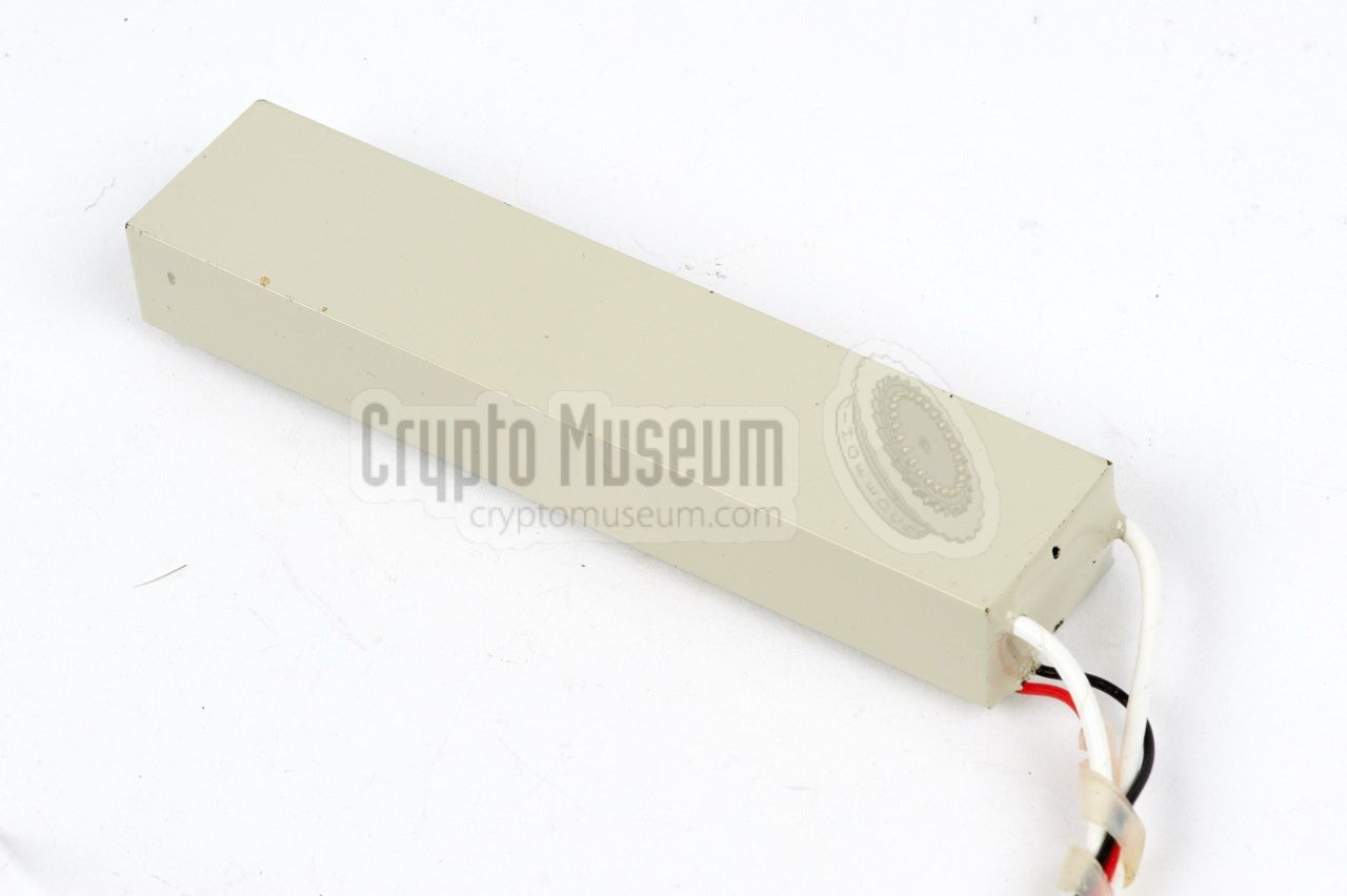
The SRT-90 is in fact a low-power variant of the
SRT-91 that was released
one year earlier. It is housed in a similar rectangular brass enclosure,
that measures 13.5 x 22.5 x 100 mm; one 1cm shorter than the SRT-91.
The reason for using a low-power version, is that it is more difficult
to detect than a medium or high power version.
The SRT-90 was intended for deployment in operations where the Listening
Post (LP) was close to the Target Area (TA). In such cases a Path Loss
Survey System, such as the URS-1, was used first to
determine the required power.
|
|
|
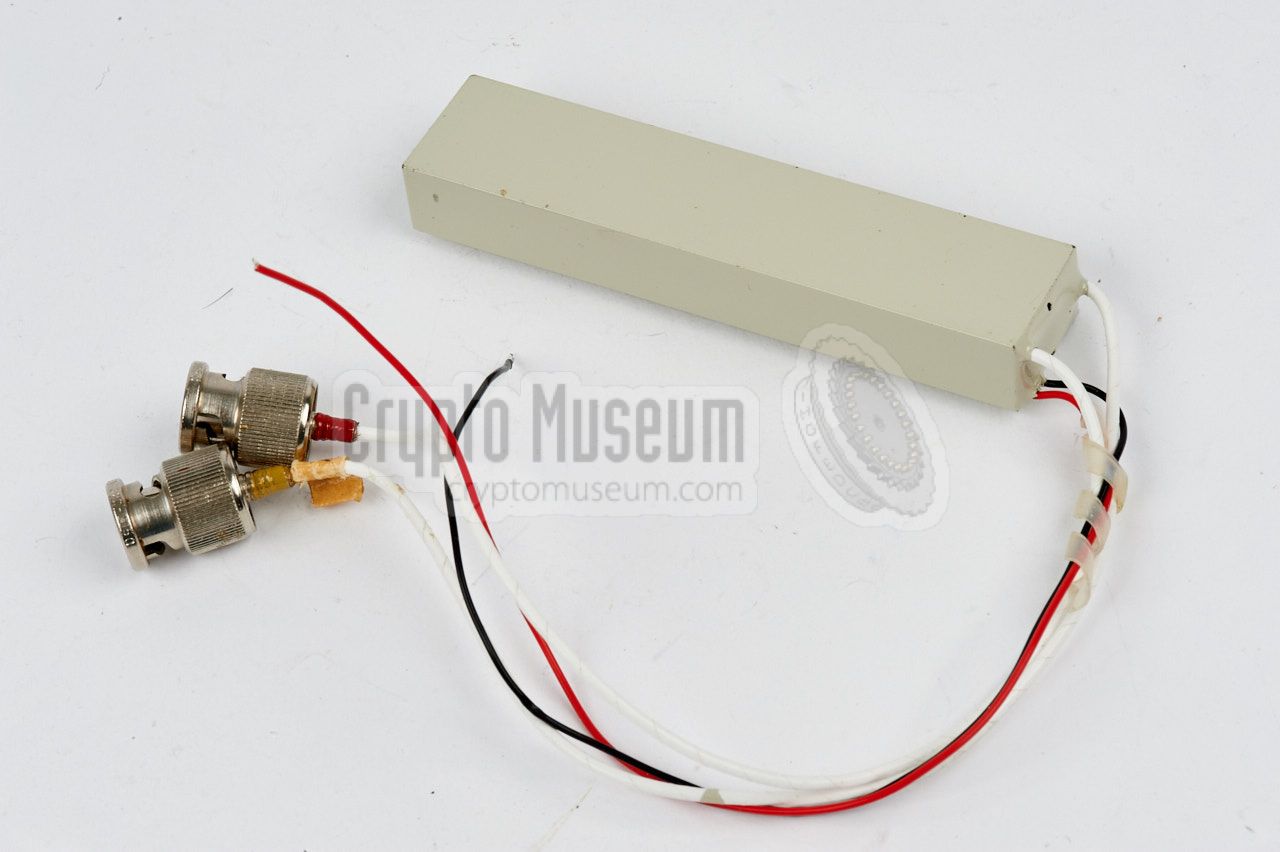
The device consists of an RF module that operates between
270 and 400 MHz, and a video coder for the Dirty Pulse (DP) 1 audio masking
scheme, housed in a single brass enclosure.
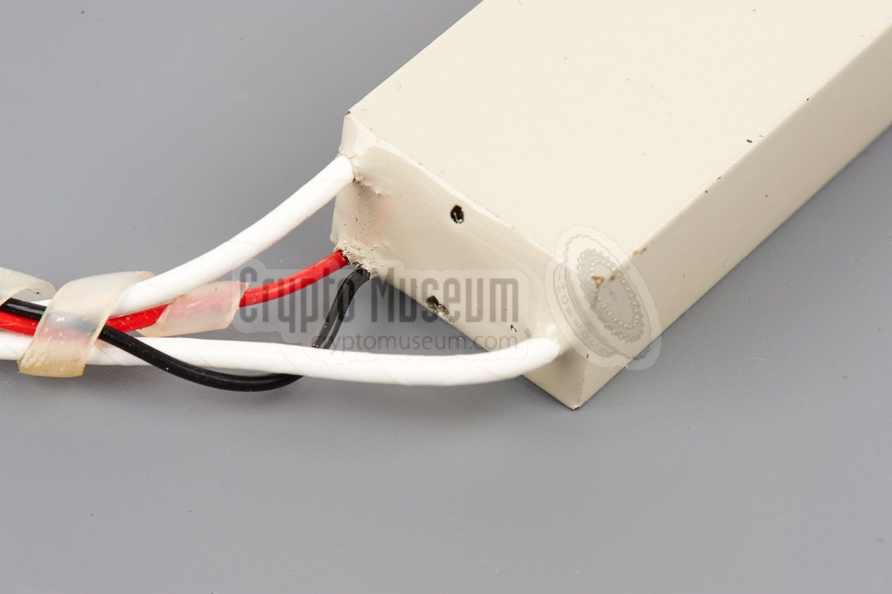
It could be powered by a DC source between +2.25V and 3.25V, generally
consisting of two military-grade mercury cells, and consumes
typically 160µA, whilst delivering a peak-output-power of 1 mW.
|
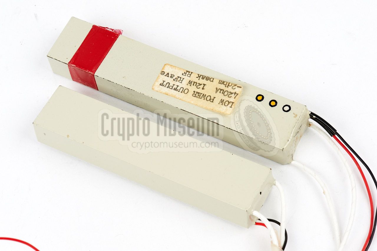
The image on the right shows the RF-unit of the SRT-90 aside the RF-unit
of the SRT-91, which delivers a peak output power of 20 mW. Because of the
lower power, the last stage of the RF-unit (i.e. the PA) has been omitted
in the SRT-90.
The rest of the circuits, which consists of a microphone amplifier, a noise
generator and a video encoder, are identical to those of the SRT-91, which
means that both transmitters can be received with the same receivers.
➤ For further details, check out the SRT-91
|
|
|
-
Dirty Pulse (DP) audio masking is also known as Type 91 modulation.
|
|
The SRT-90 operates on a pre-determined spot frequency between 270 and 400 MHz,
that is factory adjusted. The selected frequency is presented as a suffix to
the transmitter's model number (e.g.: SRT-90-A). The following frequencies
were used (± 5 MHz):
|
- 275 MHz
- 295 MHz
- 315 MHz
- 335 MHz
- 355 MHz
- 375 MHz
- 395 MHz
|
- Technical Manual for SRT-90
NRP, June 1975. CM302507/A.
- Technical Manual for SRT-90 Transmitter (concept)
NRP, September 1975. CM302507/B.
- Operation and Test Manual for SRT-90 Transmitter
NRP, December 1975. CM302507/C.
|
- NRP/CIA, Collection of documents related to SRT-90
Crypto Museum Archive, CM302507 (see above).
- Study of Further SRS-91 System Developments
NRP, October 1973. CM302629/F.
|
|
|
|
Any links shown in red are currently unavailable.
If you like the information on this website, why not make a donation?
© Crypto Museum. Created: Thursday 09 March 2017. Last changed: Monday, 21 November 2022 - 14:43 CET.
|
 |

|
|
|