|
|
|
|
|

|
|
NRP CIA EC SRS-153 QRR-153 →
The transmitter consists of three modules: a modulator, a noise generator
and an RF-unit, each of which is housed in a separate metal enclosure.
Each module is hermetically sealed and has its connections at the short sides.
The modules could be mounted separately inside a concealment, but the
complete transmitter was also available in a single pre-wired enclosure
for quick deployment. The transmitter produces a continuous wave (CW)
radio signal. Its carrier is frequency modulated (FM) with a
22 kHz subcarrier
that is frequency modulated by the audio.
|
|
|
In addition, a strong noise signal is injected into the transmitter's baseband
signal. This noise, which resembles the natural noise in an empty radio channel,
is added to hide (i.e. mask) the presence of the subcarrier which carries
the actual audio signal. The drawback of a CW system is that it consumes quite
a bit of power, as a result of which its battery life is rather limited.
Furthermore, subcarrier bugs (SC)
are easily discovered with a
professional bug tracer of the era, such as the
ScanLock Mark VB.
For these reasons, the transmitter is remote controlled by means of the
separate QRR-153 switch-receiver.
It is housed in a similar enclosure and is activated by the
QRT-153 activation-transmitter.
The SRT-153 operates on a spot frequency in the
260-320 MHz band, whilst delivering 5 mW of power.
The remote activation signal is in the 70 MHz band.
|
|
The SRT-153 was available in two case-variants:
|
- Three-piece version
The basic version of the SRT-153 came as a
three-piece solution; one for
each individual circuit.
It is a copy of an alien bug that was found
inside a wooden drawer divider in the
desk of a US Ambassador in the mid-1970s. The complete bug, including the
enclosures and the concealment, was meticulously copied by the CIA
and its subcontractor NRP.
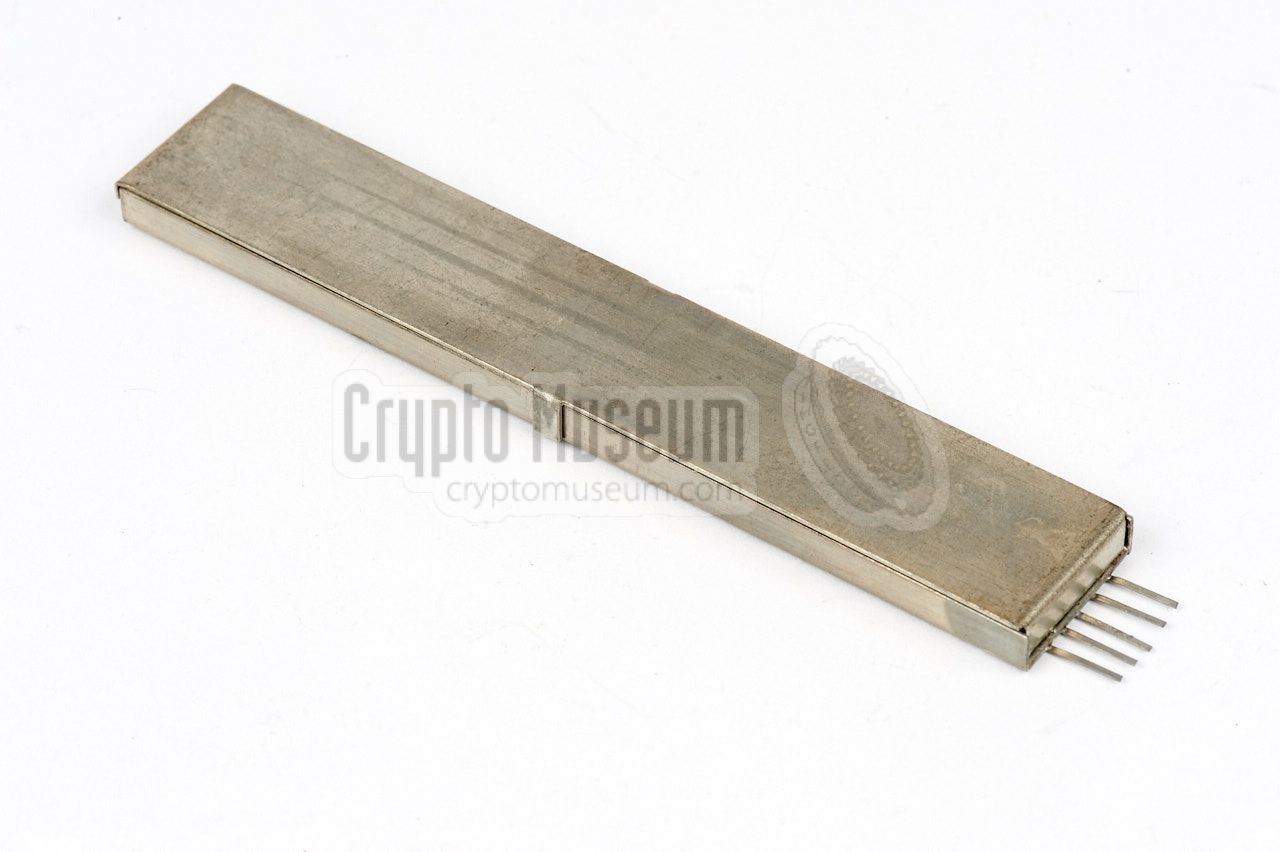
- Single-piece version
In this version, the three individual pre-fabricated modules are
mounted inside a single metal enclosure
that is filled with silicone paste.
It is based on a later version of the alien bug described above.
Power, antenna and microphone are connected to the
five contacts at one of the short sides.
The unit measures 106 x 18 x 6 mm.
|
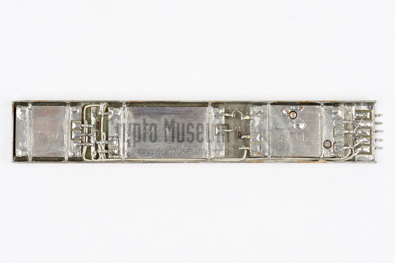
The diagram below shows the contents of the single-piece variant in which
we see the bottom side of the three individual modules, each of which is
housed in its own metal enclosure. At the left is the noise generator, which
is the smallest of the three modules. The largest one is the
subcarrier-modulator at the centre. The rightmost module is the
adjustable 290 MHz RF-unit.
At the far right are five wire terminals for connection of a microphone,
an antenna and the power supply. The latter is provided via the
QRR-153 switch-receiver. The modules are interconnected via
thin PVC wires and two factory-selected resistors to determine
the Noise/SC signal ratio.
|
The diagram below shows a complete setup of the
SRS-153 system.
The SRT-153 transmitter is installed at the target area (TA) at
the bottom right (shown in red). It is powered by two strings of
five Mallory mercury cells each, under control of the
QRR-153 switch-receiver at the top right.
At the listening post (LP), which is generally located across the
street from the target area, is the
QRT-153 activation transmitter,
which can send two carriers (one for the ON command and one for OFF)
via a frequency in the 70 MHz band. It has presets for controlling
up to four QRR/SRT-153 sets simultaneously. Once activated, the
signal from the SRT-153 transmitter can be picked up by the
SRR-153 surveillance receiver
at the bottom left. The latter can also be replaced by an
SRR-90 receiver which has been modified for
the reception of subcarrier-modulated transmitters.
|
The SRT-153 transmitter consists of three separate circuits, each
of which is built as a separate module, as shown in the diagram below.
At the left is the microphone. It is connected to the subcarrier
modulator (SC), which consists of a pre-amplifier with AGC and
a subcarrier oscillator.
It produces a frequency modulated subcarrier (FM/SC), which
is fed to the RF-unit at the right.
At the bottom is a random noise
generator, of which the output is also fed to the RF-unit. Both signals
are frequency modulated onto the RF carrier.
The noise is injected into the signal's baseband, first of all to mask
its presence, but also to hide the presence of the modulated subcarrier.
|
The SRT-153 is actually an accurate copy of an alien bug that was discovered
by the CIA in the mid 1970s in the desk of one of its Ambassadors.
It was hidden inside a wooden divider of one of the drawers of his
desk. The image below shows the layout of the divider, with the three
modules of the transmitter highlighted in red. In this case, the three
separate modules are used, but later variants have been found in which
the transmitter was housed in a single metal enclosure.
It is currently unknown why the CIA copied the design of an adversary,
while they had access to far better technology from a variety of sources.
A possible explanation is that they wanted to put the blame on the
adversary if the bug was discovered, or that it was used
as a bait to satisfy an alien sweep team,
and that other bugs, of a different nature, were also present
at the target area.
➤ Read the full story
|
To hide the RF carrier and its modulation from regular
surveillance receivers,
professional bugs often use a special technique
that is known as
audio masking.
The SRT-153 uses a sophisticated masking scheme, in which
a 22 kHz frequency modulated subcarrier, is frequency modulated
onto the 290 MHz RF carrier, whilst at the same time
injecting noise in the channel's baseband.
This technique is known as
subcarrier audio masking
and defeats any non-compatible receiver.
It is safe enough to hide the signal from an unexperienced eavesdropper
and to prevent accidental demodulation in a standard receiver.
A similar technique is used in the CIA's
SRT-105
and in the OPEC bug,
although the latter injects a strong 50 Hz hum into the baseband
rather than noise.
➤ More about subcarrier audio masking
|
|
In order to obtain a clear reproduction of the original audio,
the signal from the SRT-153 should be demodulated with a compatible
professional receiver that can handle subcarrier-modulated
and noise masked signals, such as the SRR-153
that was designed especially for this purpose.
|
The image on the right shows a typical SRR-153. It was developed
in 1981 and released in 1982. The SRR-153 was commonly used at the heart of
a Listening Post in combination with an
SRN-9 antenna. It can also
demodulate other types of subarrier bugs that work in the
same frequency range, such as the SRT-93
and the SRT-105.
Before the SRR-153 became available in 1982,
existing SRR-90 receivers
were upgraded for the reception of subcarrier bugs, by replacing three
of its plug-in modules. This introduced a 10.7 MHz IF-stage and a 22 kHz
SC demodulator.
|
|
|
The first generation of the SRR-153 receiver was only suitable for the
reception of the SRT-153 transmitter.
A later version was also able to demodulate the 40 kHz
subcarrier signal from the SRT-93
and SRT-105 bugs,
but for this the position of a jumper on the audio board had to be changed.
For the older SRR-90 receiver, a separate 40 kHz demodulator plug-in was
produced.
➤ More about the SRR-153
|
-
Only when the appropriate subcarrier-compatible plug-in modules are installed.
|
|
As the SRT-153 produces a continuous wave signal, it is easier
to find than pulse-based bugs like the SRT-56.
Furthermore, it consumes more energy as a result of which it has
a reduced battery life. For these reasons it was commonly used
in combination with the QRR-153 switch-receiver.
|
The switch-receiver controls the power supply to the transmitter,
and is powered itself by a single mercury battery cell.
In order to save power, it is only switched on for
23 ms every 1.5 seconds.
In the short time that it is active, it responds to two command
signals: one to turn the SRT-153 ON, and one to turn it OFF again.
It is estimated that the QRR-153 can run this way for one full year
on a single mercury cell. The image on the right shows the QRR-153
receiver aside the somewhat longer encapsulated SRT-153 transmitter.
It is also available in a 2-piece variant.
|
|
|
|
The SRT-153 transmitter is powered by two parallel strings of five cells each.
By switching it off between sessions, e.g. during the night, precious battery
power is saved. It is estimated that the transmitter can also run for one full
year, when it is used for an average of eight hours each day.
|
Having the ability to control the bug remotely, is also very useful
if the surveillance team at the listening post (LP) notices the arrival
of a sweep team at the target area.
In such situations, the transmitter can be switched
off to reduce the chance of detection.
As soon as the sweep team has left, the transmitter can be activated again.
The QRR-153 switch-receiver was controlled via a signal in the 70 MHz band,
sent by the QRT-153 activation transmitter shown in the image on the right.
It has a built-in telescopic antenna and has the ability control up to
four targets.
|
|
|
|
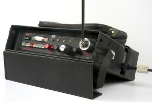
Despite the fact that the SRT-153 features a professional-grade
audio masking technique, bugs of this type can be discovered relatively
easy with a bug detector, such as the
Audiotel Delta V,
or with a professional bug tracer, like the
Audiotel Scanlock Mark VB
shown in the image below.
|
When trying the Scanlock in the vicinity of an active SRT-153,
it was able to lock onto its RF carrier, demodulate the subcarrier,
and produce a clear audio signal, in less than a second.
Likewise, the
Audiotel Delta V bug detector
was able to detect the SRT-153 at a distance of 10+ metres. By using its tone indicator with
signal-strength dependent pitch, we were able to find the bug in less
than one minute.
Nevertheless, it provides reasonable security against an
average interceptor, especially because it can be turned
OFF remotely whenever a sweep team is spotted.
|
|
|
But despite the fact that the bug can be switched OFF remotely, it is no
match for a so-called non-linear junction detector (NLJD), which is able
to find nearly any piece of electronic circuitry, even if it is switched
off. As the two-stage RF-unit is coupled directly to the antenna,
it is vulnerable to the NLJD. Other CIA bugs, like the
SRT-107
had special anti-NLJD provisions.
➤ More about the Scanlock bug tracer
➤ Example of an NLJD
|
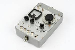
Because of the wide variety of subcarrier-modulated bugs used by the CIA,
produced by different contractors, there were sometimes difficulties when
trying to receive their signals on an SRR-153
or the earlier SRR-90
receivers. In many cases it was unclear whether this was caused by the bug
or by the receiver.
For this reason, the NRP developed the UVK-153 transmitter tester,
which is able to check every aspect of a bug unambiguously.
➤ More information
|
|
|
|
The SRT-153 transmitter consists of three different circuits,
each of which is built on a separate printed circuit board (PCB)
and housed in a separate enclosure. The three modules hold the
RF-unit,
the subcarrier modulator
and the noise source,
and are interconnected by thin white wires.
|
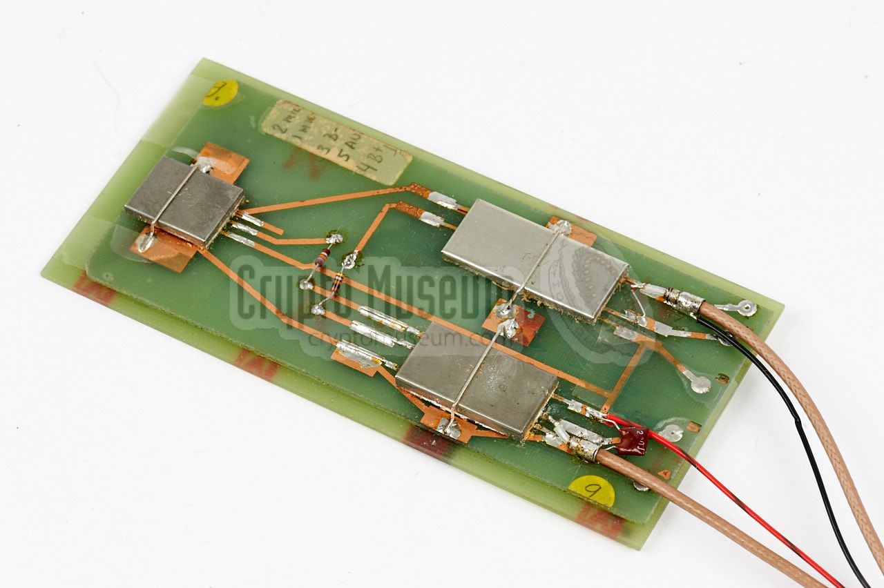
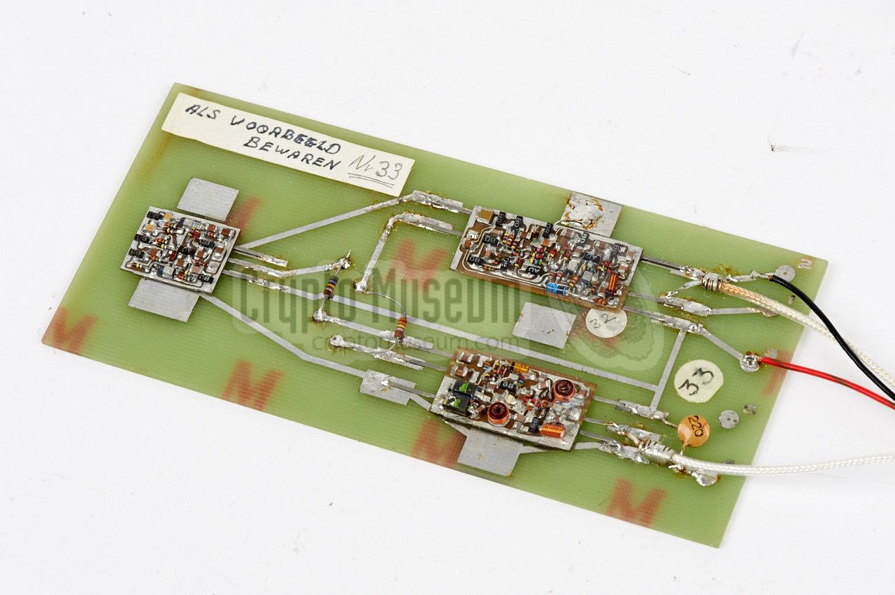
The image on the right shows the individual circuit boards mounted
on a test panel. It was used at the laboratory as
a reference model.
The PCBs are a close copy of the alien original, both in the choice of
the components and in choice of production methods.
Even the engraving of the serial
numbers, the numbering scheme and the markings of the terminals, was
nearly identical.
All three PCBs are single-sided.
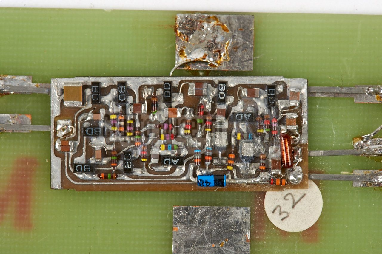
As can be seen in the close-ups below, chip capacitors are used, as well as
SMD transistors, but the resistors are conventional subminiature
types with wires.
|
|
|
Again, this was done to copy every aspect of the discovered alien bug.
Although some circuits were improved by the NRP, such
as the operational temperature range, this was
done in a nearly invisible manner, so that even the originating agency
would not be able to identify it as a copy.
|
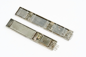
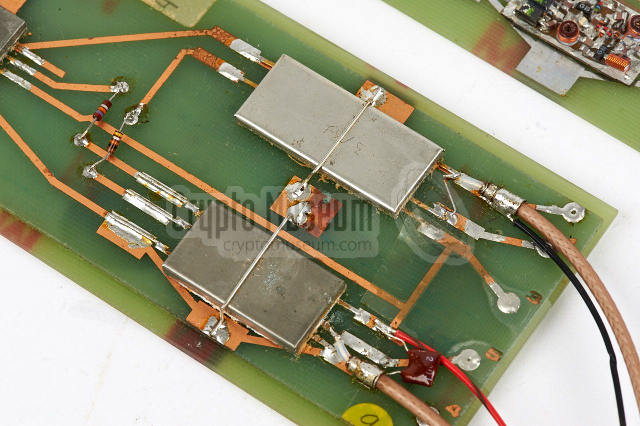
In the actual production version, each of the three units
is housed in a separate metal case
that is filled with KF-400 silicone paste [2]. When the units
were finished and adjusted, they were soldered onto a temporary PCB,
with wires for power, microphone and antenna.
This was done to allow the CIA to do an acceptance test,
and to soak test the units prior to deployment.
The image on the right shows a production board aside the laboratory model.
Each of the modules has a number of long connection wires, that will later
be shortened to the desired length.
|
|
|
When built inside a wooden desk drawer divider, as in the original example,
the three individual modules were glued to the bottom of the concealment by
means of thin pieces of double-sided adhesive phenolic. The modules were then
interconnected by means of thin white PVC wiring.
|
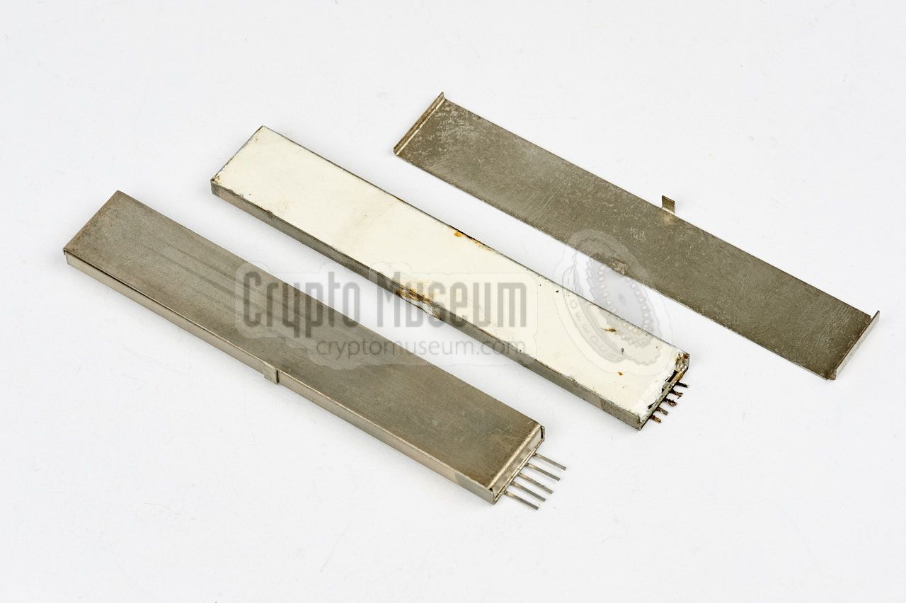
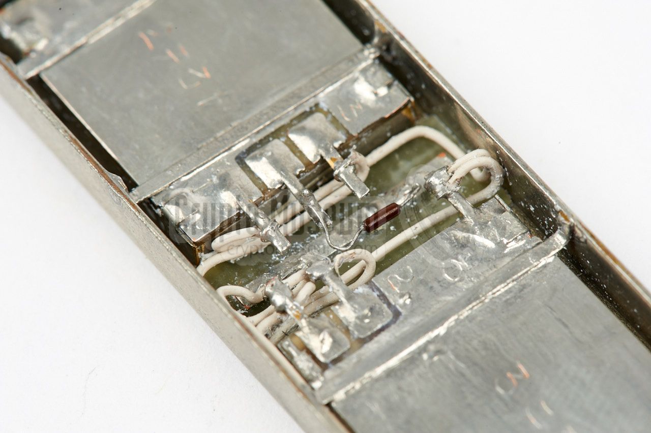
With later versions of the original desk drawer divider bug, the three
modules were housed inside a single long metal enclosure, with five wire
terminals at one of the short sides. In that case, the
modules were fitted to the bottom of the enclosure,
which was then filled with
a thick white silicone paste, and soldered hermetically.
The image on the right shows the single-piece version of the SRT-153,
both open (rear) and closed. Removing the paste is extremely difficult
and is likely to damage the components, as the CIA found out
when analysing the original bug.
|
|
|
Like the 3-piece variant, the single-piece encapsulated version was
mounted onto a temporary PCB
prior to delivery to the CIA, to allow
acceptance and burn-in testing. Mounting the devices inside a concealment
was not the NRP's responsibility, but was done elsewhere, probably by
the CIA or by another contractor. Is is currently unknown how and
where the bugs were deployed.
|
|
The diagram below specifies the wiring of the five contact terminals of
the SRT-153 transmitter. Note that pins 2 and 4 are internally connected to
ground and that the device is powered by a negative voltage (i.e. plus
connected to ground), whilst the QRR-153 receiver
is powered by a positive voltage and has the negative connected to ground.
Power is between 2.7V and 8.1V.
|
- Microphone (signal)
- Microphone (ground)
- Power supply (-V)
- Ground (+V)
- Antenna
|
|
The diagram below shows how the SRT-153 is wired to the
QRR-153 switch-receiver. The negative terminal of the battery
array is directly connected to pin 3 of the transmitter, whilst the positive
terminal is switched by the receiver. The receiver itself is powered by
a separate 1.35V mercury battery. It has a built-in energy saver that switches
it on for just 23 ms every 1.5 sec.
Note that transmitter and receiver each have their own antenna, which
more or less resembles a dipole. One half of the dipole is formed by the
antenna wires, whilst the ground wiring acts as the other half. In the
orignal desk drawer divider
(in which the bug was first found),
the ground wires are clearly visible just above the battery array.
Antennas of this kind are by no means ideal.
|
Device Continous wave subcarrier modulated covert listening device Manufacturer NRP Customer CIA Frequency 260 - 320 MHz (with a channel spacing of 10 MHz) Subcarrier 22 kHz ± 1.5 kHz (-10°C and +50°C) Power 2.2 - 4.5V (typically: 2.7V), max. 6V Current 10 mA at 2.7V Output 5 mW at 2.7V, 2.5 mW at 2.2V Link budget > 104 dB (when using SRR-90 receiver) Temperature 3 MHz drift between -10°C and +50°C Storage -20°C and +70°C
|
- XSRT/XQRR-53 Operating Notes
NRP, October 1977. CM302627/A.
- Proposal for Prototype SRS/QRS-53
NRP, November 1977. CM302627/B.
- Environmental Test Report on XSRT-53 Transmitter
NRP, August 1979. CM302627/F.
- Environmental Test Report on XQRR-53 Receiver
NRP, August 1979. CM302627/G.
- Operation and Test Manual for SRT-153 & QRR-153
NRP, April 1980. CM302627/H.
- Operation and Test Manual for SRT-153 & QRR-153
NRP, May 1980. CM302627/I.
- Operation and Test Manual for SRT-153 & QRR-153 (draft)
NRP, September 1980. CM302627/J.
- Operation and Test Manual for SRT-153 & QRR-153
NRP, September 1981. CM302627/N.
|
- NRP/CIA, Collection of documents related to SRS-153
Crypto Museum Archive, CM302627 (see above).
|
|
|
|
Any links shown in red are currently unavailable.
If you like the information on this website, why not make a donation?
© Crypto Museum. Created: Thursday 18 May 2017. Last changed: Friday, 25 November 2022 - 17:14 CET.
|
 |

|
|
|