|
|
|
|
|

|
|
NRP CIA EC SRS-153 SRR-153 → ← SRT-153
The QRR-153 is part of the SRS-153 surveillance system and
reponds to ON/OFF command tones between 14 and 24 kHz, sent
by a QRT-153 activation transmitter
that operates on a factory-set spot frequency in the 68 - 78 MHz
frequency band. The frequencies of the command tones are also factory-set
and are accurately determined by
two externally fitted miniature capacitors.
The receiver is operated from a single 1.35V mercury cell.
To save power, it is only switched on for 23 ms every 1.5 seconds.
It is estimated that it can operate this way for one full year.
|
|
|
An electronic switch, that is part of the QRR-153, controls the power
supply to the SRT-153 transmitter,
so that it can be turned off when it is not needed, e.g. during the night.
This way valuable battery power can be
saved, whilst it also allows the surveillance team at the listening post
to turn the transmitter off if the risk is too high, e.g. when a sweep
team has been spotted.
The switch-receiver consists of three modules: a small superregenerative
receiver and a two-tone decoder, each mounted in a separate metal case,
plus an electronic switch that controls the power supply to the SRT-153
transmitter (i.e. the bug).
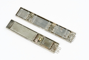
The modules could be used separately,
but were generally mounted together in a
single metal case,
with the switching unit mounted between
the receiver and the decoder, as shown in the image above.
The remaining space was then filled with a thick white silicone paste, after
which the unit was hermetically soldered.
|
|
The QRR-153 was available in two case-variants:
|
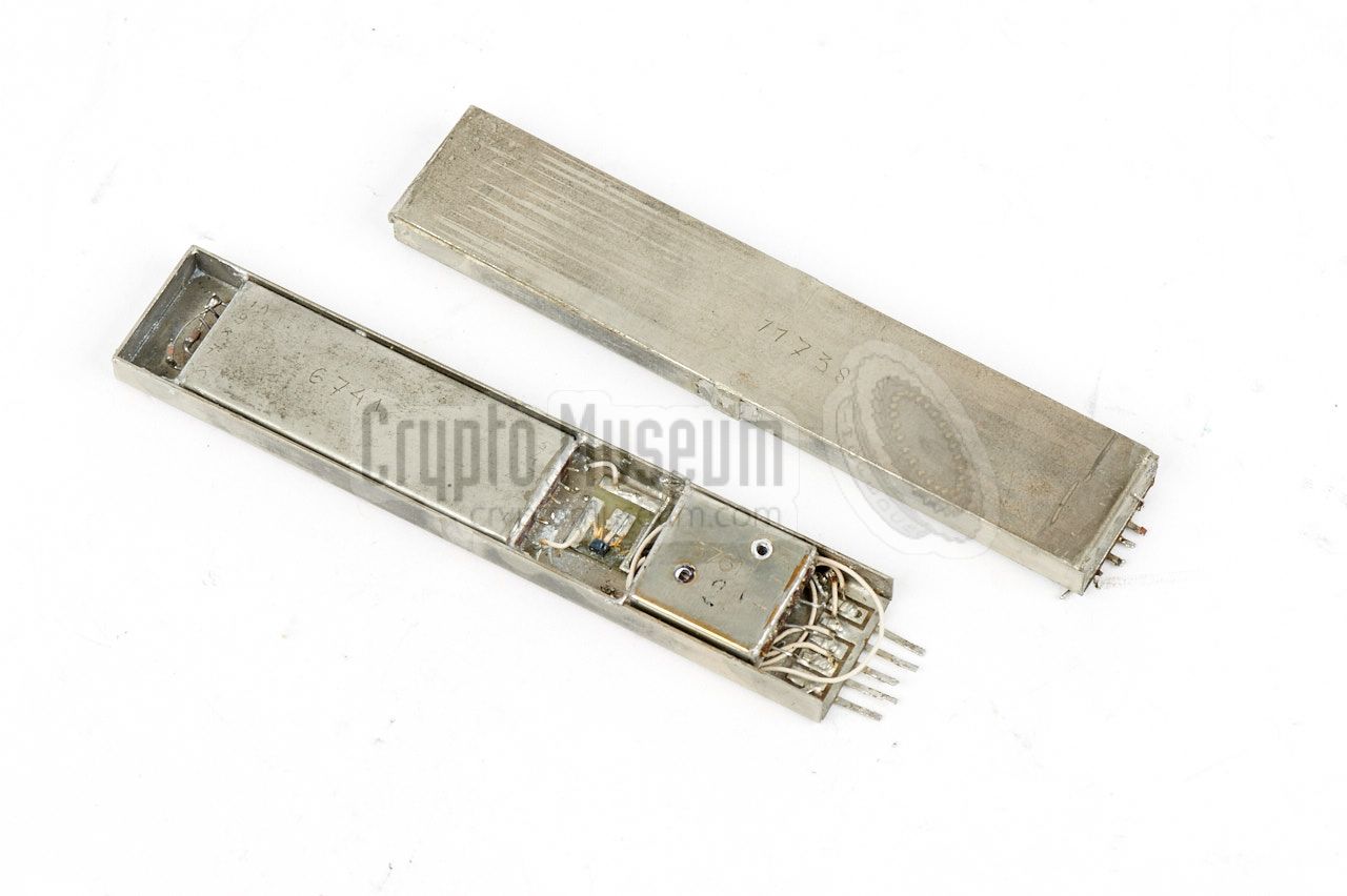
The image below shows the interior of the QRR-153, after the top cover
has been taken off, and the protective white silicone paste has been
removed. The actual receiver is housed in the small square metal enclosure
at the right. The bigger metal enclosure contains the tone decoder, which
is 'programmed' by means of two external capacitors that are soldered to
the wire terminals.
A single Siemens BC123 NPN transistor is mounted on a small PCB that is fitted
in between the receiver and the decoder modules. It acts as the electronic
switch that controls the power supply to the SRT-153 transmitter.
At the far right are the terminals for microphone, antenna and power.
|
The diagram below shows a complete setup of the
SRS-153 system.
The QRR-153 switch-receiver is installed at the target area (TA) at
the top right (shown in red). It is powered by a single
Mallory mercury battery cell, and controls the power supply of the
SRT-153 transmitter.
At the listening post (LP), which is generally located across the
street from the target area, is the
QRT-153 activation transmitter,
which can send two carriers (one for the ON command and one for OFF)
via a frequency in the 70 MHz band. It has presets for the control
up to four QRR/SRT-153 sets simultaneously. Once activated, the
signal from the SRT-153 transmitter can be picked up by the
SRR-153 surveillance receiver
at the bottom left, or by a modified
SRR-90 receiver.
|
Below is the block diagram of the QRR-153 receiver. At the left is the
superregenerative receiver which is pulse-operated by a battery saver that
is part of the decoder module. The IF output of the receiver (video) is fed
to two different tone filters inside the decoder module. They control
the on/off state of a latch circuit, that in turn controls the external
electronic transmitter switch.
The decoder is powered by a single 1.35V mercury battery, that indirectly
powers the receiver. The power for the transmitter
is provided by a string
of 5 mercury cells that are connected in series, entering the external
switch at the top right, and controlled by the state of the latch.
|
The QRR-153 is actually an accurate copy of the switch-receiver of
an alien bug that was found by the CIA in the mid 1970s in the
desk of one of its ambassadors.
It was hidden inside a wooden divider of one of the drawers of his
desk. The image below shows the layout of the divider, with the
receiver highlighted in red. It consists of three parts:
a receiver, a decoder and a switch.
It is currently unknown why the CIA copied an adversary's design,
whilst they had access far better technology from a variety of sources.
A possible explanation is that they wanted to put the blame on the
adversary if the bug was discovered, or that it was used
as a bait to satisfy an alien sweep team,
and that other bugs, of a different nature, were also present
at the target area.
➤ Read the full story
|
Although in principle, the QRR-153 switch-receiver can be used for remote
controlling virtually any kind of bug, it was developed especially for use
alongside the SRT-153.
The SRT-153 is housed in a similar metal enclosure, but is somewhat longer
than the QRR-153. Furthermore it should be powered by a negative voltage,
which explains the need for the extra switching transistor in the QRR-153.
➤ More information
|
|
|
In order to save power, the QRR-153 receiver is only switched on for
23 ms every 1.5 seconds. During the short time that it is active, it
accepts ON and OFF commands sent by a transmitter in the 70 MHz band,
in the form of a subcarrier.
The image on the right shows the QRT-153 activation transmitter, or actuator,
that was developed especially for this purpose. It has provisions for
controlling up to four QRR/SRT-153 sets simultaneously.
➤ More information
|
|
|
|
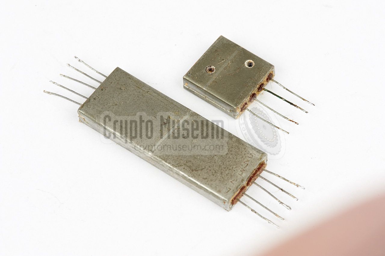
The QRR-153 consists of three modules, two of which (the receiver and the
decoder) are housed in an individual metal enclosure. The third module is
no more than a single transistor, mounted on a small PCB. It acts as the
electronic switch that controls the power supply to the SRT-153.
|
When encapsulated in a single enclosure, the electronic switch is mounted
in the small space between the receiver and the decoder. The two other modules
are solder-mounted to the sides of the enclosure.
Like with the SRT-153 bug,
the modules of the QRR-153 are filled with a sticky white silicone paste, which
makes it very difficult to examine the interior.
We are currently unable to show the interior of the receiver module.
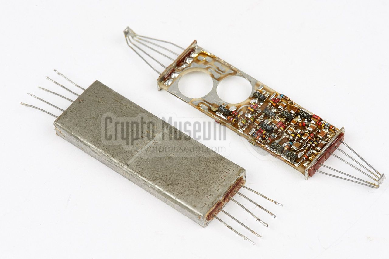
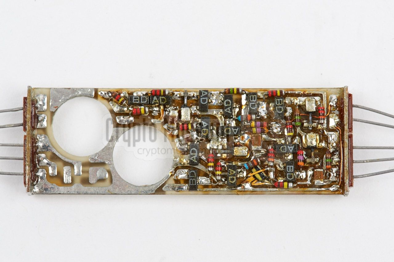
Although the same is true for the tone decoder module, we have found the partly
assembled bare one that is shown in the image on the right.
|
|
|
It is shown here aside a completely assembled encapsulated one. The tone decoder
is built on a double sided PCB with components at both sides. The two large
holes are for the Siemens ferrite inductors that are missing here. The inductors are used for the precision circuits that recognise the ON and OFF
tones, sent by the QRT-153 activation transmitter
at the listening post (LP}.
|
In order to provide some level of customisation,
The exact frequencies of the command tones are determined in combination
with two externally fitted capacitors.
These capacitors are soldered directly to the wire terminals of the
decoder module at the far end of the outer enclosure.
Once the individual modules were completely assembled, they were
fitted onto a temporary test board, as shown in the image on the right.
This allowed full testing and adjustment of the modules. In case of the
three-piece variant, the QRR-153 was delivered to the CIA this way.
|
|
|
In case of the single-piece variant, the individual modules were mounted
inside a long metal enclosure and filled with white silicone paste. The
case was then hermetically soldered and the complete unit was mounted on a
slightly different test board. The single unit
measures 93 x 18 x 6 mm.
After acceptance and soak testing by CIA technicians,
the modules were removed from the temporary boards and built inside the
chosen concealment for actual target area deployment.
Although the construction of the QRR-153 is similar to that
of the SRT-153 transmitter, there are significant differences in
manufacturing and construction techniques, indicating that the
original devices (from which these were copied) may have been manufactured by
different suppliers.
|
|
The diagram below specifies the wiring of the five contact terminals of
the QRR-153 receiver. Note that pins 1 and 4 are internally connected to
ground and that the device is powered by a positive voltage (i.e. minus
connected to ground), whilst the SRT-153 transmitter
is powered by a negative voltage and has the plus connected to ground.
The receiver is powered by just 1.35V.
|
- Ground (-V)
- Power supply (+V)
- Switched output
- Ground (-V)
- Antenna
|
|
The diagram below shows how the QRT-153 is wired to the
SRT-153 transmitter. The negative terminal of the battery
array is directly connected to pin 3 of the transmitter, whilst the positive
terminal is switched by the receiver. The receiver itself is powered by
a separate 1.35V mercury battery. It has a built-in battery saver that switches
it on for just 23 ms every 1.5 seconds.
Note that transmitter and receiver each have their own antenna, which
more or less resembles a dipole. One half of the dipole is formed by the
antenna wires, whilst the ground wiring acts as the other half. In the
orignal desk drawer divider
(in which the bug was first found),
the ground wires are clearly visible just above the battery array.
Antennas of this kind are by no means ideal.
|
- XSRT/XQRR-53 Operating Notes
NRP, October 1977. CM302627/A.
- Proposal for Prototype SRS/QRS-53
NRP, November 1977. CM302627/B.
- Environmental Test Report on XQRR-53 Receiver
NRP, August 1979. CM302627/G.
- Operation and Test Manual for SRT-153 & QRR-153
NRP, April 1980. CM302627/H.
- Operation and Test Manual for SRT-153 & QRR-153
NRP, May 1980. CM302627/I.
- Operation and Test Manual for SRT-153 & QRR-153 (draft)
NRP, September 1980. CM302627/J.
- Operation and Test Manual for SRT-153 & QRR-153
NRP, September 1981. CM302627/N.
|
- NRP/CIA, Collection of documents related to SRS-153
Crypto Museum Archive, CM302627 (see above).
|
|
|
|
Any links shown in red are currently unavailable.
If you like the information on this website, why not make a donation?
© Crypto Museum. Created: Thursday 18 May 2017. Last changed: Monday, 21 November 2022 - 13:29 CET.
|
 |

|
|
|