|
|
|
|
|

|
|
CIA NRP EC SRS-91 ← SRR-91
In its basic configuration, the SRR-90 is suitable for the reception
of pulse-modulated (PPM) bugs that feature the
Rejected Pulse (RP)
or Dirty Pulse (DP)
audio masking schemes, such as the
SRT-56,
SRT-107 2
and SRT-90/91 transmitters.
In addition, it can be modified
for the reception of 22 kHz or 40 kHz subcarrier (SC) modulated bugs,
by swapping three of the modules.
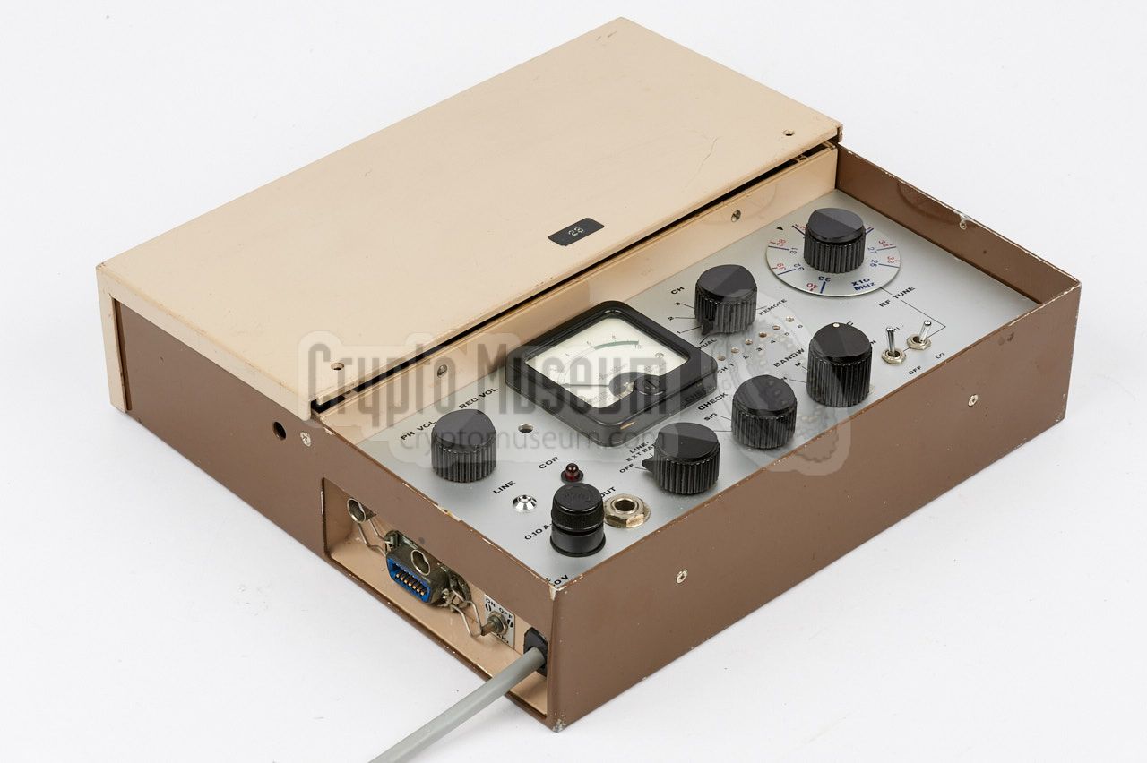
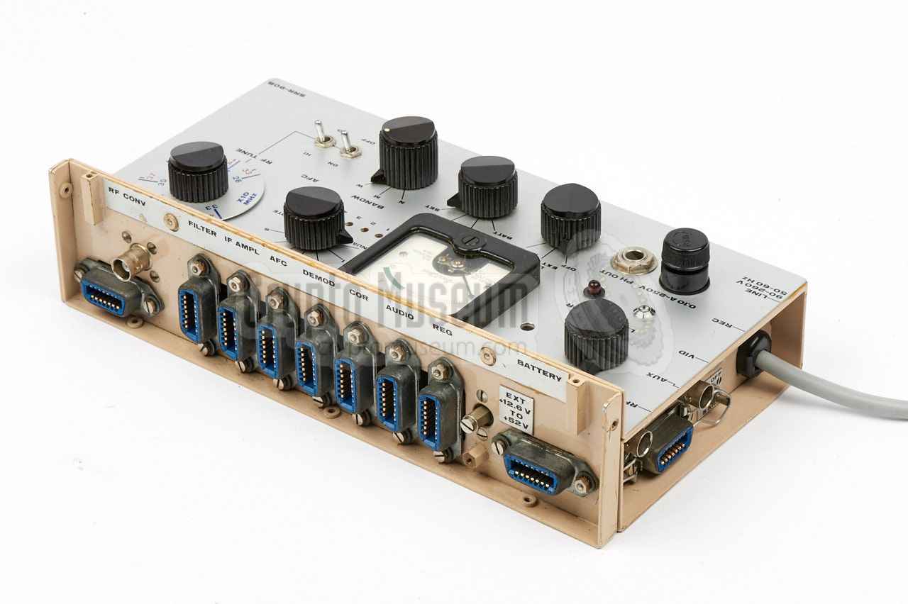
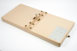
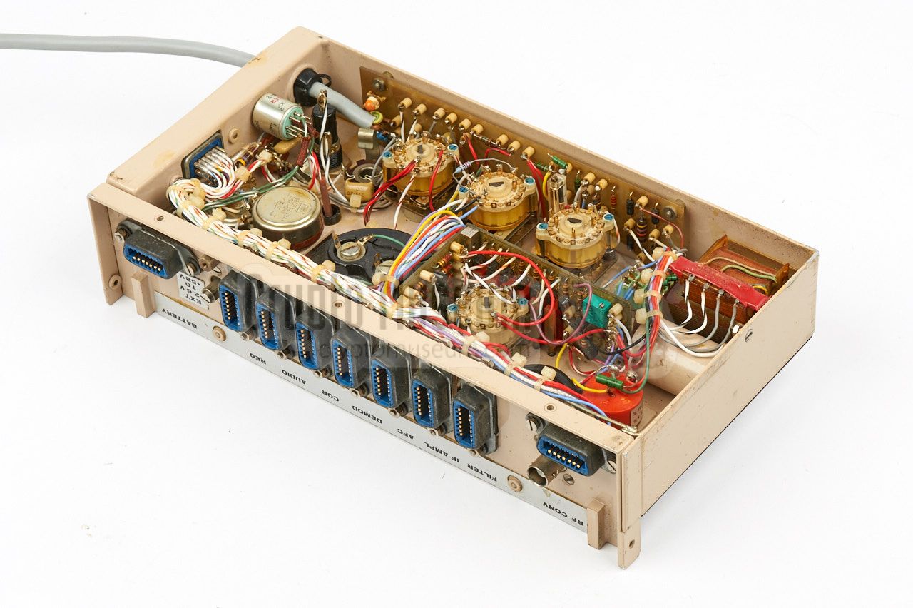
The image on the right shows the SRR-90B, which was intended
for horizontal use and was usually installed inside a regular Samsonite
briefcase. The modules are installed below the beige panel.
|
|
|
The SRR-90 was developed during the course of 1973 and 1974, following
a request of the CIA to study possible improvements of the
SRR-91,
and started life as the SRR-91 Mark II in November 1974 [3].
After further modifications and improvements,
it finally went into production during the course of 1975 as the
SRR-90. 1
During its lifetime it was upgraded and improved several times.
|
In 1978 it was discovered that the receiver was susceptible
to interference from the ignition of cars and motor cycles [J].
Motorola,
another CIA contractor, had already successfully modified
the circuits of the earlier SRR-52 receiver,
but this appeared not to be suitable for
the SRR-90, so the NRP had to devise a different solution [2].
The SRR-90 was one of the most successful and flexible products
developed by the NRP. It had an extremely long lifespan, not least because of
its expandability, and was used
by the CIA well into the 1990s, long after the demise of the NRP.
|
|
|
In 1991, a batch of SRR-90 receivers was returned to the
manufacturer (NRP)
for reburbishment and modification. The receivers were re-aligned,
repaired and optimised, as a result of which the modules were no longer
interchangable with those of another SRR-90. At the same time,
the pulse demodulator module (SLR-5)
was modified for the reception of
the SRT-99 transmitter.
As part of the refurbishment, the updated
receivers were given a new serial number (1001 onwards).
In April 1993, shortly before the NRP closed its doors, a special
Test Generator for the SRR-90 receiver was developed and supplied
to the CIA [Y]. It simulated the signals from pulse-based transmitters
such as the SRT-91,
but also from transmitters built by other CIA contractors.
|
 |
-
Although its model number suggests otherwise,
the SRR-90 was developed and produced about one year
later than the SRR-91.
The reason for this is the fact the SRR-91 was initially known as
the SRR-91 Mk I, whilst the enhanced version — to be produced
later — would be the SRR-91 Mk II. However, when the SRR-91 Mk II was
ready for release, the CIA decided to rename it SRR-90.
-
For the reception of the SRT-107,
the SRR-145 down-converter is
required as well. This is also the case for the high-band version
of the SRT-56.
|
|
The SRR-90 was available in the following models, making it suitable
for a wide variety of bugging operations. Each model is described in more
detail below.
|
- SRR-90 A
Upright version with all controls at the front. Connections at
the left and right bottom. Intended for desktop use. Modular
construction, not easily accessible.
- SRR-90 B
Flat version with all controls at the top. All connections at
the left side. Total height 60 mm.
Suitable for operation inside a standard briefcase. Modular
construction, easily accessible by lifting the flap that covers
the rear half.
- SRR-145
With the addition of the SRR-145 down-converter,
both models can be adapted for the reception of transmitters in the
1300-1600 MHz frequency range,
such as the SRT-107 and the high-band version
of the SRT-56.
|
|
The SRR-90 has all characteristics and features of the
earlier SRR-91, plus the following:
|
- Two case variants: upright (A) and flat (B)
- Automatic frequency correction (AFC)
- 6 preset channels
- Automatic selection between RP (56) and DP (91) masked signals
- Relay output, activated when locked onto a proper signal (COR)
- Headphones socket at control panel (rather than at the side)
- Remote control of the preset channels (via AUX socket)
|
|
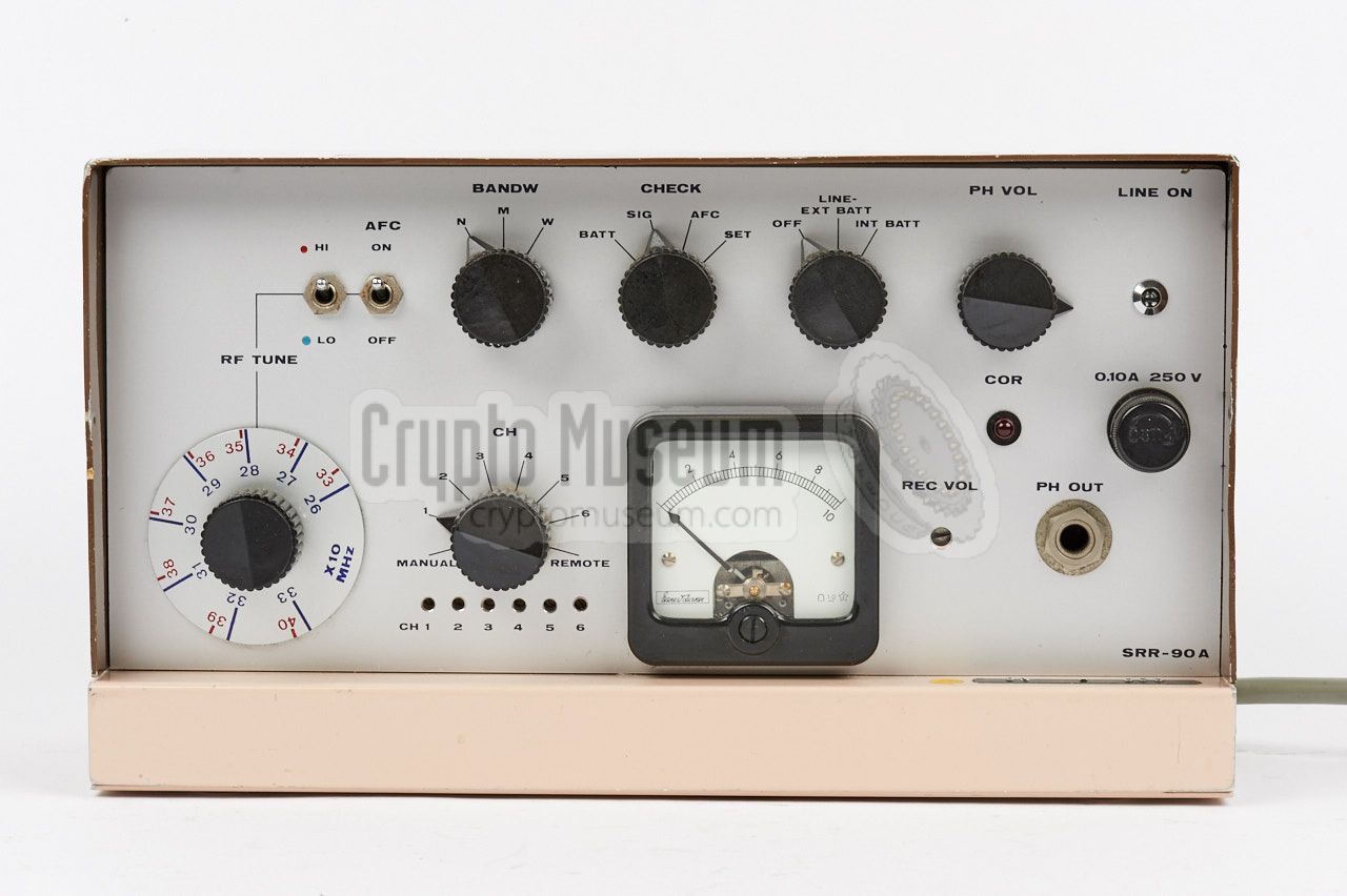
The basic SRR-90A model is intended for desktop use. The unit measures
just 26 x 15 x 11 cm, and has all controls at the front panel. The
connections are at the bottom of the left and right sides, with the exception
of the headphones bus, which is at the bottom right of the front panel.
|
This model is intended for use in narrow spaces, such as on a shelf or in
a mobile installation.
The unit is powered from the 90-240V AC mains, or from internal
standard 9V block batteries.
The radio consists of a so-called
main frame into which a series of
plug-in modules are installed.
The receiver covers a frequency range of 260 to 400 MHz, divided over 2
bands, selectable with a toggle switch and marked LO and HI.
The image on the right shows a typical SRR-90A. At the left is the
tuning knob with its two scales in 10 MHz units: 260-330 MHz (LO) and 330-400 MHz (HI).
|
|
|
Getting access to the interior of the SRR-90A is rather cumbersome, and
involves the removal of six screws from the dark brown cover. This means
that replacing the internal batteries is not very convenient. In practice,
this model was usually powered directly from the 90 - 240 V AC mains.
|
|
|
SRR-90 B
horizontal model
|
|
|
|
The SRR-90B is functionally identical to the SRR-90A, but is constructed
differently so that its hight never exceeds 6 cm, allowing it to be
installed in a regular Samsonite briefcase of the era.
It has a rectangular shape that measures 26 x 24 cm, making it
slightly wider than the SRR-91.
|
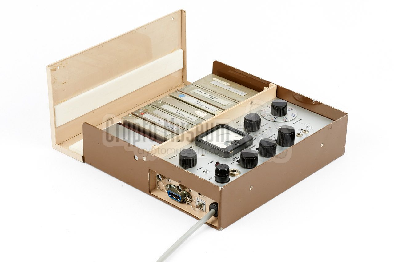
The image on the right shows a typical SRR-90B as seen from the front right.
The case consists of two halfs, of which the front one is occuplied by
the mainframe
and the rear half holds the plug-in modules.
The mainframe holds the recessed control panel,
which is nearly identical to that of the SRR-90A,
but has a different arrangment.
The rear half is covered by a beige hinged lid that is held in place by two
screws. This provides easy access
to the battery and the modules, making this model more suitable for
portable use in areas where mains power is not available.
|
|
|
In practice the two screws were often omitted, so that the rear compartment
could be accessed more easily. This was particularly useful if the receiver
was also used for the reception of
subcarrier (SC) modulated bugs like
the SRT-153,
in which case some modules had to be swapped.
|
A complete listening post (LP) always has an SRR-90 receiver at its heart.
Depending on the circumstances and the available space at the LP, either the
SRR-90A or the SRR-90B is selected, whichever is more suitable for the
current job.
The SRR-90A fits in a narrow space and is easily connected and operated,
but its interior is more difficult to access.
The SRR-90B offers the same features but can be concealed and transported
in a common executive style Samonite briefcase.
|
|
|
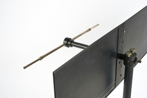
A suitable directional antenna for the SRR-90 listening post (LP)
is the SRN-9-L, or the later SRN-9. It offers a gain of 7 dB and is
in fact an adjustable dipole on a horizontal boom (which acts as a
balun), mounted in front of a reflector.
The antenna can be disassembled completely, and the reflector plane
can be folded at the centre, so that the entire unit can be stored inside
a regular briefcase, along with the SRR-90 receiver and its accessories.
➤ More information
|
|
|
The SRR-90 has two audio outputs: a fixed one for connection of a recording
device, and an adjustable one for connection of a pair of headphones.
Virtually any type of headphones with an impedance of 600Ω can be
used.
It was typically used with American military headphones of the era, such as
the one shown in the image on the right.
|
|
|
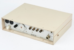
The frequency range of the SRR-90 (260 - 400 MHz) 1 could optionally be
enhanced with the 1300 - 1600 MHz band, simply by inserting the SRR-145
down-converter shown on the right,
between the antenna and the receiver's input.
This was necessary for receiving
SRT-56 units that were
equipped with a high-band SRK-145 RF module. It was also needed for the
reception of the SRT-107 transmitter.
➤ More information
|
|
|
When using the SRR-145 down-coverter shown above,
the existing SRN-9 listening post antenna has to be replaced by
one that is suitable for the 1300 to 1600 MHz frequency
range.
The SRN-55 is a flat stacked-dipole antenna that covers the entire
range and offers a gain of approx. 17.5 dB.
➤ More information
|
|
|
|
A complete SRR-90 consists of a mainframe with 9 modules, each of which has a
label with the model and serial number. For optimum performance, the
serial numbers should match. 1 For additional functionality, alternatives
for some of the modules were made available.
|
SLR-1 RF converter 260-400 MHz (low: 260-330 MHz, high: 330-400 MHz) SLR-2 IF Filter SLR-3 IF Amplifier 60 MHz SLR-4 AFC-60 MHz SLR-5 Pulse Demodulator SLR-6 COR SLR-7 Audio Amplifier SLR-8 Regulator SLR-9 Battery Pack
|
-
This is only the case for SRR-90 receivers that were refurbished in 1991,
and that have a serial number of 1001 or higher. In the original series (serial
number below 1000) the modules were interchangable.
|
|
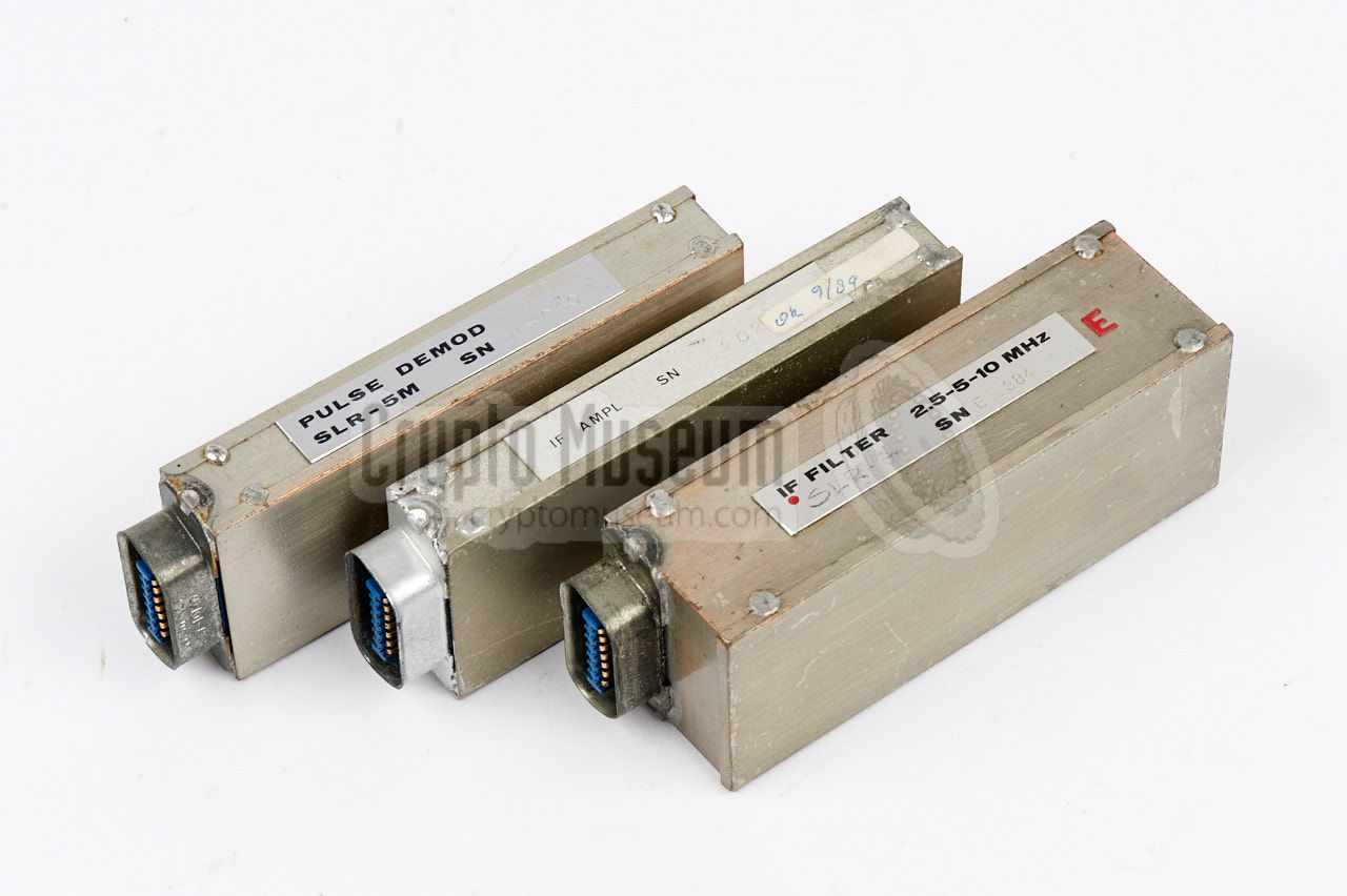
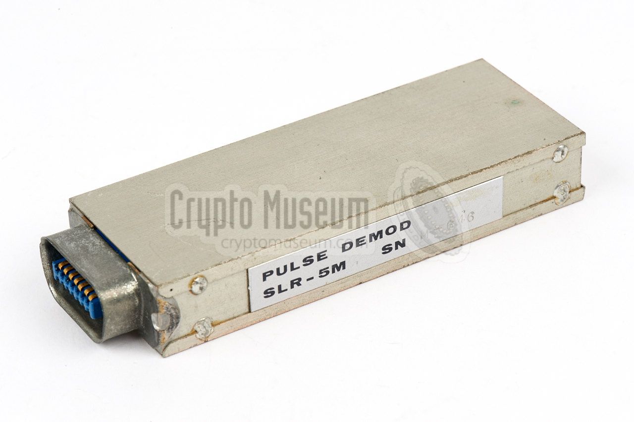
Around 1978, the following modules were modified for immunity against pulse-type
radio interference, such as the suprious signals caused by the ignition of
cars and motor cycles. The modified modules were given the suffix 'M'.
|
SLR-3M IF Amplifier 60 MHz SLR-5M Pulse Demodulator
|
|
|
Alternative frequency range
|
|
|
|
The frequency range of the SRR-90 can be changed by swapping the SLR-1
for one of the following modules:
|
SLR-15 RF converter 390-520 MHz SLR-16 RF converter 235-360 MHz (low: 235-290 MHz, high: 290-360 MHz) SLR-16* RF converter 235-360 MHz (low: 235-300 MHz, high: 300-360 MHz)
|
|
|
Alternative audio masking
|
|
|
|
In its basic configuration, the SRR-90 was only suitable for the reception
of pulse-type signals. By swapping the
following modules, it could be
modified for the reception of bugs with
subcarrier audio masking (SC).
As SC-masked bugs use much less bandwidth than pulse-based systems,
the entire IF section had to be replaced.
The following modules were available as an
upgrade kit:
|
SLR-2
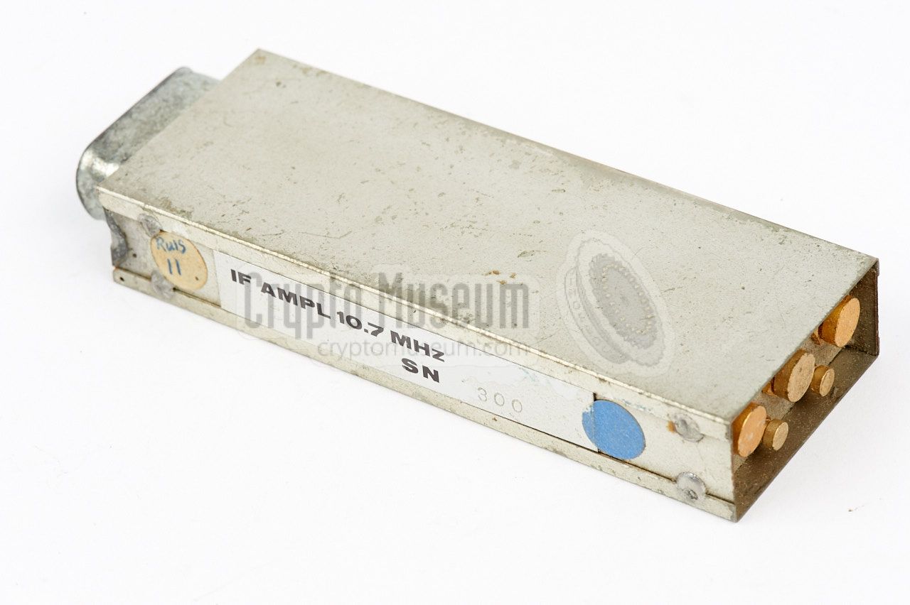
SLR-10 IF Converter 60 →10.7 MHz SLR-3
SLR-11 10.7 MHz Amplifier SLR-5
SLR-12 40 kHz Demodulator SLR-17 22 kHz Demodulator (alternative for SLR-12)
SLR-13 IF PSK Demodulator SLR-14 Digital Decoder
|
The block diagram below shows the SRR-90 in its basic configuration
in which it is suitable for the reception of pulse-based transmitters.
At the bottom is the mainframe that acts as a carrier for the
controls, the connections, the mains PSU and the
plug-in modules
SLR-1 thru SLR-9.
|
| |
Wideband configuration for reception of Pulse Position Modulation
|
The antenna is connected to the mainframe, but is directly passed to the
RF converter (SLR-1) via a modified BNC socket. The SLR-1 is tuned to the
desired frequency and converts it to a 60 MHz wideband signal, which is
filtered in SLR-2 and then amplified in SLR-3. The actual demodulation of
the pulse-based signals is done by the SLR-5, which automatically selects
between RP and DP audio masking. After that, the signal is amplified to
headphones level in SLR-7. The COR unit (SLR-6) produces a delayed
confidence signal that can be used to control an external recorder.
|
| |
Narrowband configuration for reception of subcarrier masked signals
|
The block diagram above shows the same receiver, but modified for the
reception of transmitters with
subcarrier audio-masking (SC).
This is done by swapping modules SLR-2, SLR-3 and SLR-5 for
SLR-10, SLR-11 and SLR-12 respectively.
Subcarrier bugs produce a continuous wave signal (CW),
with a much narrower bandwidth than a pulse-transmitter.
The SLR-10 module converts the 60 MHz signal from the tuner to the more
common 10.7 MHz, which is then amplified in SLR-11.
The SLR-12 module contains a double FM demodulator. It first demodulates
the carrier signal, and then demodulates the resulting 40 kHz subcarrier,
resulting in a clear reproduction of the original audio.
As in practice different
frequencies were used for the subcarrier, alternatives for the SLR-12
may have to be used in order to obtain proper locking.
One example is the SLR-17.
|
|
Like its predecessor – the SRR-91
– the SRR-90 consists of a
mainframe
and a set of plug-ins,
or modules, that are housed together in an
aluminium enclosure with a removable cover.
The mainframe occupies about half the available space, whilst
the other half is taken by the modules.
|
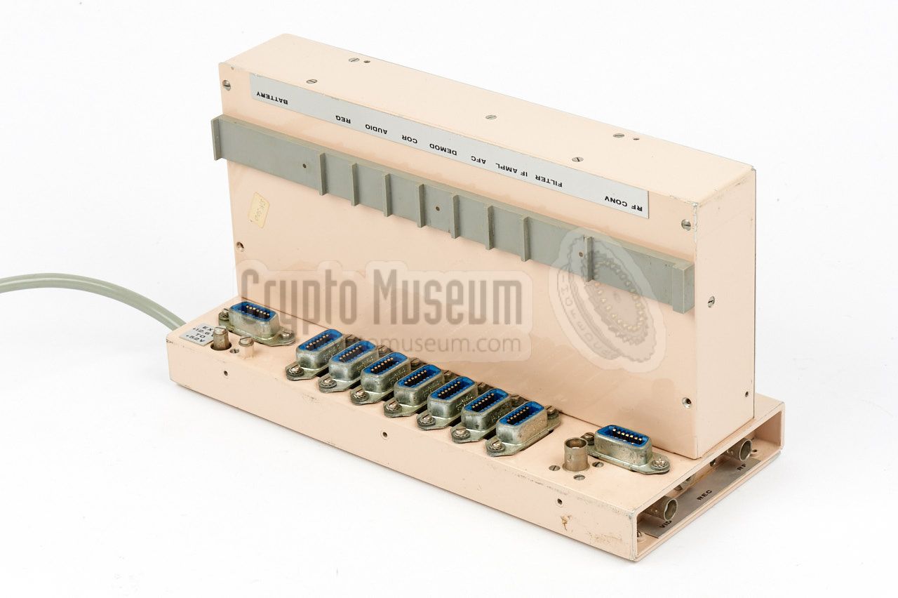
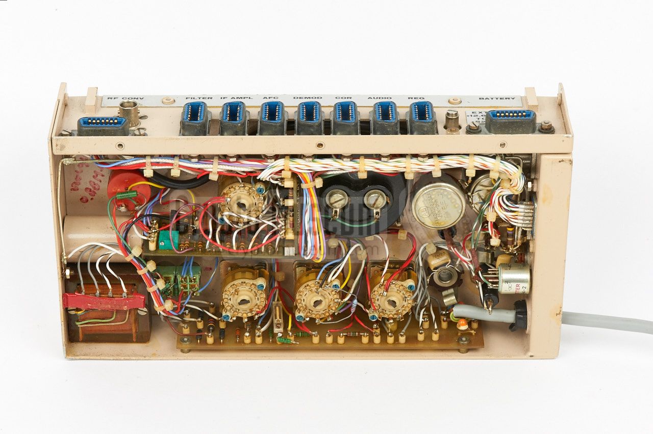
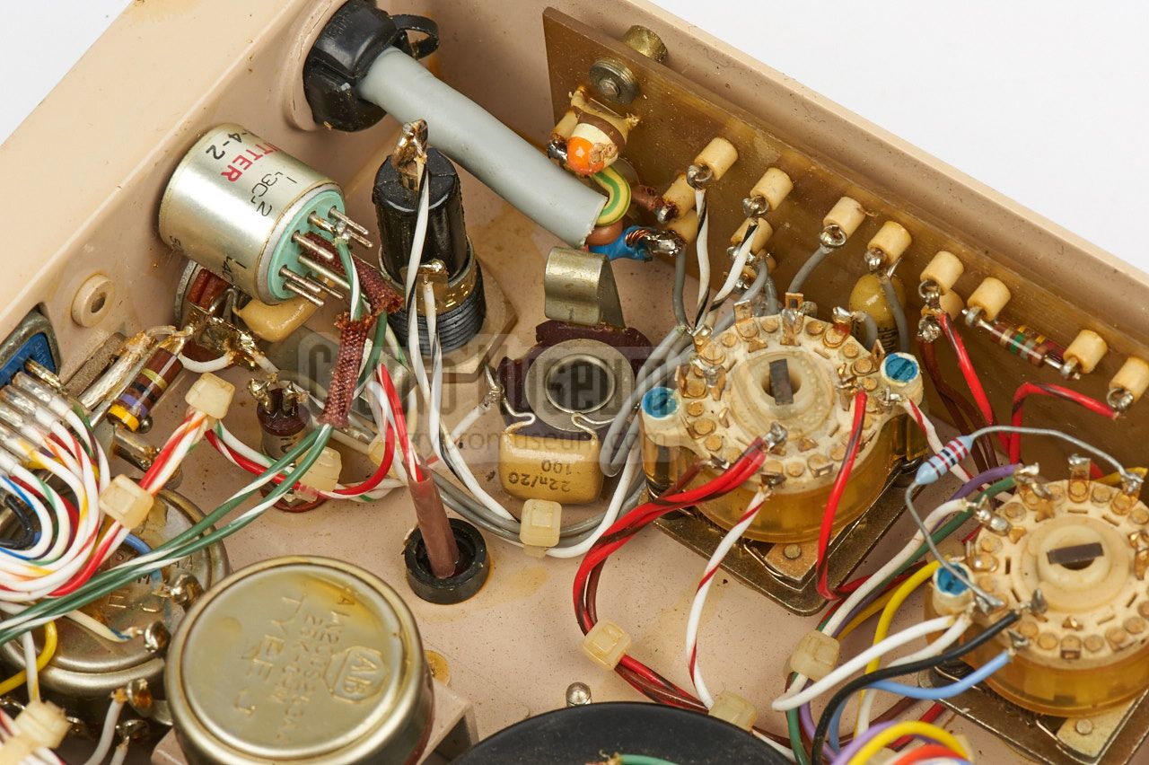
The image on the right shows a bottom view of the interior of the mainframe
of the SRR-90B, as seen from the rear left. It shows the internal wiring and
the sockets, or slots, for the plug-in modules. Apart from the
mains PSU,
the mainframe does not contain any active components.
At the top is the mains power lead
that is guided to the transformer in the
opposite corner. To the left of the mains cable, the wiring of the AUX bus
is clearly visible. It allows remote control of the preset channels.
The mainframe of the SRR-90A has a different layout but is otherwise
identical.
|
|
|
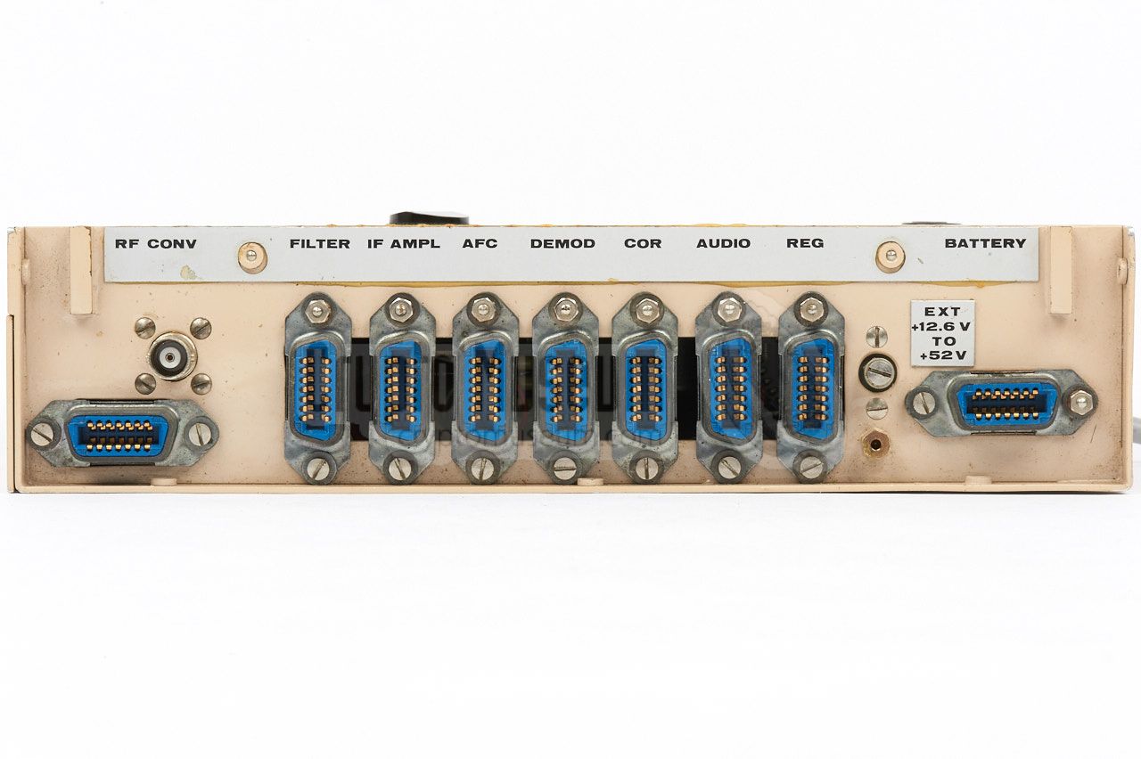
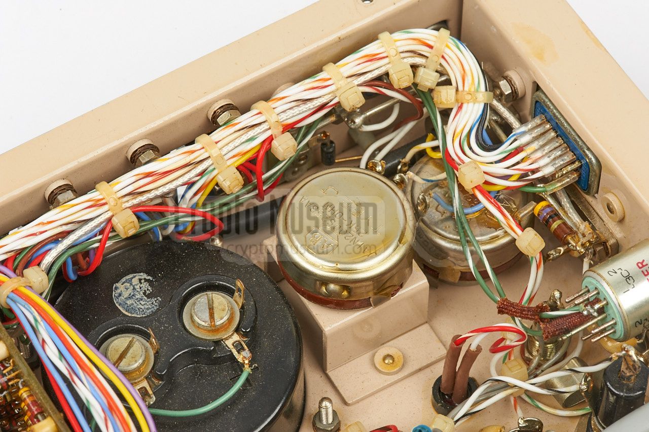
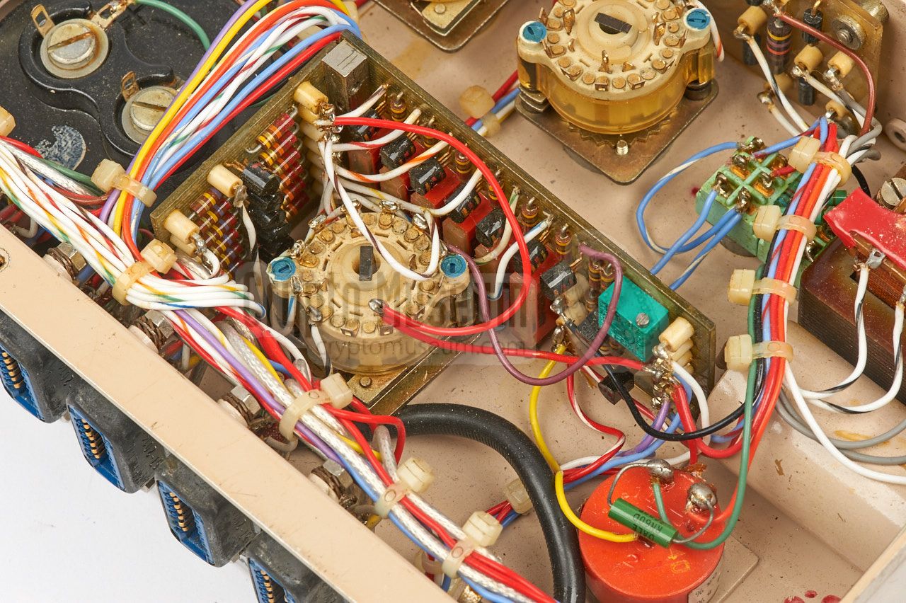
Each module is assigned a dedicated slot with a 14-pin socket.
Although all sockets are identical, a module should only be installed
in the slot that carries its name. The two horizontally placed sockets
are for the RF converter and the battery. Note that the RF unit is also
connected to a BNC socket that carries the antenna signal. The use of
plug-in modules, made the SRR-90 extremely service friendly and allowed
quick and easy adaption to alternative
audio-masking schemes.
|
|
When the SRR-90A and SRR-90B receivers featured on this page were rediscovered
in 2016, they were fully disassembled, With them, a collection of
unidentified plug-in modules was found. With help from the accompanying
documentation, Crypto Museum has meanwhile been able to bring them both to
life again. The SRR-90A, of which the interior is more difficult to access,
has been configured for the reception of RP and DP masked bugs and can be
demonstrated in combination with the RP-masked SRT-56
and the DP-masked SRT-91 bugs.
|
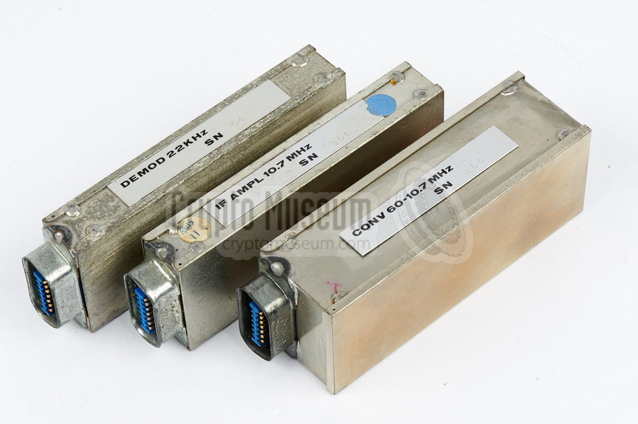
The SRR-90B is fitted with modules that provide the same basic functionality
as the SRR-90A, but has an alternative set of modules on the side, allowing
it to be converted for the reception of subcarrier (SC) bugs within a
few seconds. The image on the right shows the
three alternative modules
that have to be fitted inside the unit, to make it suitable for the
reception of SC bugs.
The receiver can now be demonstrated with
the RP-masked SRT-56,
the DP-masked SRT-91
and the SC-masked SRT-153.
|
|
|
- Provisional data on SRR-91-MK II Receiver
NRP, November 1974. CM302495/A
- Electrical Design Verification of the SRR-91 Mark II 1
CIA, date unknown, but probably March 1975. CM302495/B.
- Receiver alignment sequence
NRP, personal notes (Dutch). 8 October 1975. CM302495/C.
- Manual for SRR-90 A and B Receiver
NRP, December 1975. CM302495/D.
- SRR-90 Manual Amendment (ignition protection)
NRP, date unknown, but probably 1975. CM302495/E.
- Subcarrier Demodulation System (prototype)
Manual Amendment for SRR-90 Receiver.
NRP, January 1976. CM302495/F. Superseded by [H].
- Manual for SRR-90 A and B Receiver
NRP, March 1976. CM302495/G.
- Subcarrier Demodulation System
Manual Amendment for SRR-90 Receiver.
NRP, March 1977. CM302495/H.
- Manual for Spare Plug-in Modules for use with SRR-90A/B Receivers
NRP, March 1977. CM302495/I.
- Report on Investigation of Ignition Interference Susceptibility
In SRR-90 Receiver Systems.
NRP, February 1978. CM302495/J.
- SRR-90 Manual Amendment for use with 390-510 MHz RF Module
NRP, July 1978. CM302495/K. Superseded by [N].
- Manual for ARR-90 A and B Receiver
NRP, March 1980. CM302495/L.
- Subcarrier Demodulation System
Manual Amendment for SRR-90 Receiver.
NRP, March 1980. CM302495/M.
- SRR-90 Manual Amendment for use with RF-converter Module SLR-15
NRP, September 1980. CM302495/N.
- SRR-90 Manual Amendment for use with RF-converter Module SLR-16
NRP, September 1980. CM302495/O.
- Environmental Test Report on SLR-17 22 kHz Demodulator
NRP, July 1981. CM302495/P.
- Manual for ARR-90 A and B Receiver
NRP, March 1982. CM302495/Q.
- Subcarrier Demodulation System
Manual Amendment for SRR-90 Receiver.
NRP, March 1982. CM302495/R.
- Environmental Test Report on SRR-90 subcarrier demodulation devices
NRP, April 1982. CM302495/S.
- Manual for SRR-90 A and B Receiver - subcarrier mode (draft)
NRP, June 1983. CM302495/T.
- Manual for SRR-90 A and B Receiver - subcarrier mode
NRP, July 1983. CM302495/U.
- Environmental Test Report on SRR-90 Receiver
Receiver Modules SLR-10, SLR-11 and SLR-12.
NRP, December 1983. CM302495/V.
- Technical Manual for the SRR-90 receiver
NRP, July 1991. CM302495/W. 2
- Collection of test and acceptance sheets for SRR-90
NRP/CIA, October 1991 - January 1992. CM302495/X. 2
- Technical Manual for the SRR-90 Test Generator
NRP, April 1993. CM302495/Y.
|
|
-
During the development phase, the SRR-90 was known as the SRR-91 Mark II.
-
Issued with refurbished SRR-90 receivers that were
given serial numbers from 1001 onwards.
|
- NRP/CIA, Collection of documents related to SRS-90
Crypto Museum Archive, CM302495 (see above).
- NRP/CIA, Collection of documents related to AGC ignition interference
Crypto Museum Archive, CM302626.
- NRP, Study of Further SRS-91 System Developments
October 1973. Crypto Museum Archive CM302629/F.
|
|
|
|
Any links shown in red are currently unavailable.
If you like the information on this website, why not make a donation?
© Crypto Museum. Created: Saturday 06 May 2017. Last changed: Friday, 30 May 2025 - 09:39 CET.
|
|

|
|
|