|
|
|
|
|

|
|
Antennas CIA NRP EC
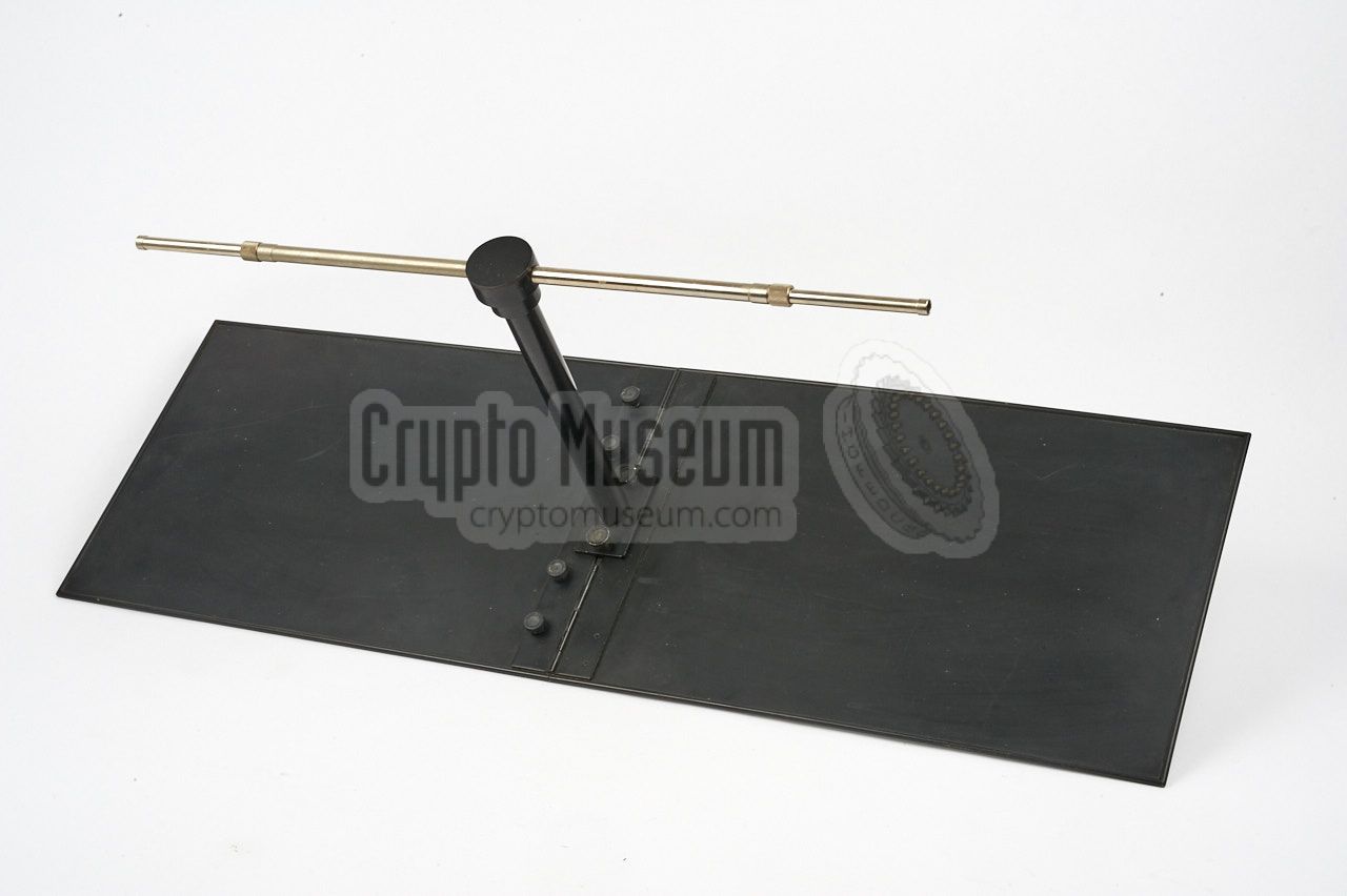
The antenna is basically an
open dipole
of which the length of the elements
can be adjusted freely (within a certain range) to match the desired
frequency. The dipole elements are mounted on a
horizontal aluminium boom
in front of a
non-resonant reflective plane
that gives the antenna its
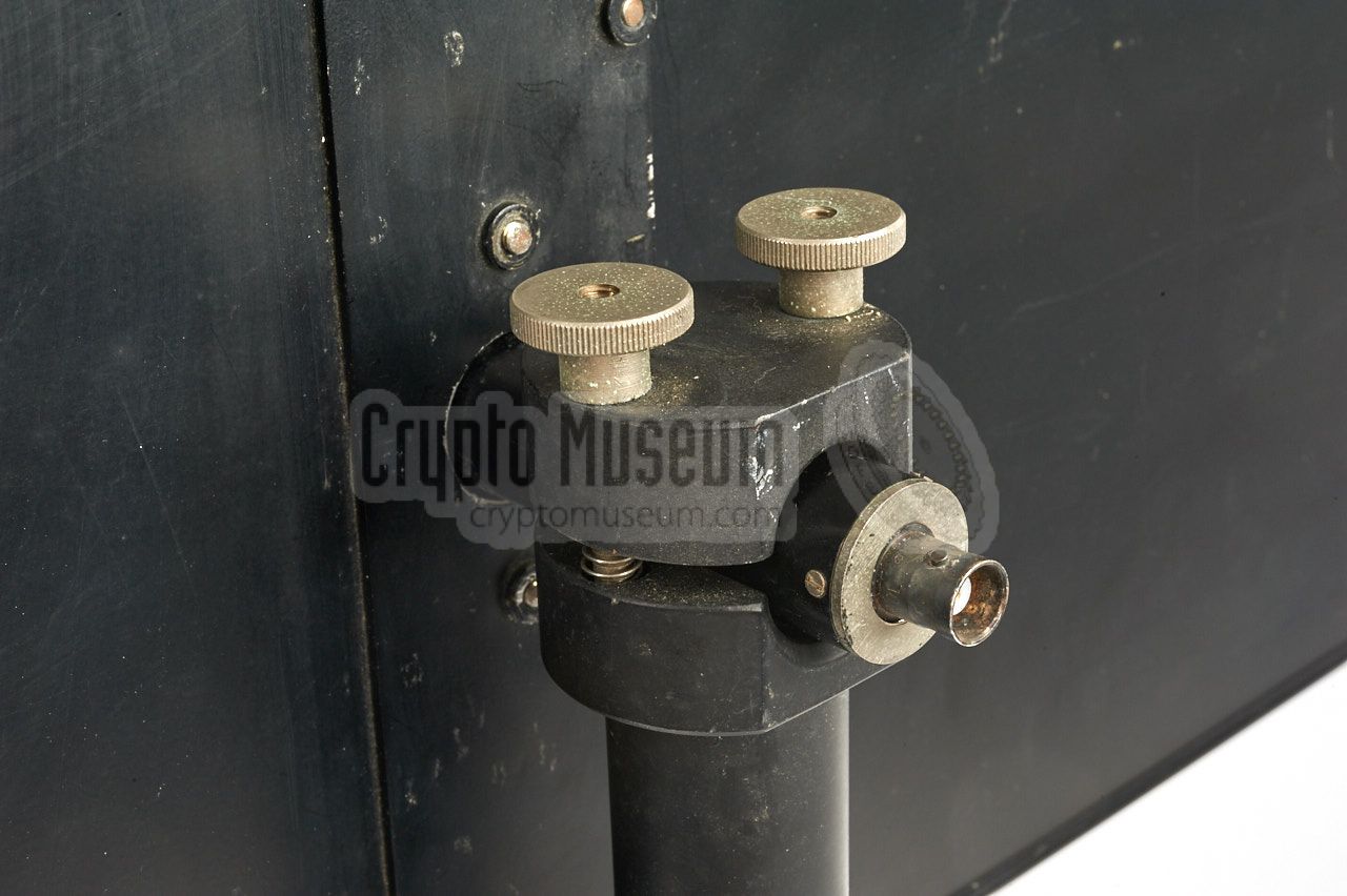
directivity and its gain. The boom also acts as a ¼λ BALUN,
and has a BNC socket at the end.
All parts of the antenna can be dismounted. The reflective plane is hinged
at the centre, allowing it to be folded and transported
in an unobtrusive standard Samsonite exectutive style briefcase.
|
|
|
Initially, there were two versions of the antenna, both of which were in
production from 1968 to 1970. The SRN-9L (low) was intended for the 240
to 330 MHz frequency range, whilst the SRN-9H (high) was suitable for
300 - 470 MHz. In 1972, both models were succeeded by the SRN-9, which
was suitable for the SRR-52
and SRR-56 and supported the
entire 240 - 470 MHz range.
|
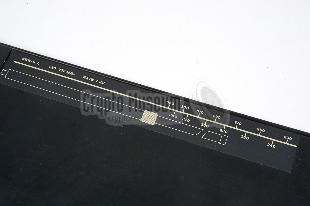
- SRN-9-L
Directive LP antenna covering 240 - 330 MHz, with 6 - 7 dB gain.
Originally supplied in 1968 with the
SRR-52 surveillance receiver
for the reception of
SRT-52 bugs.
- SRN-9-M
Non-adjustable directive antenna covering 314 - 316 MHz, with 7 dB gain.
Originally supplied in 1971 with the
URS-1 path loss survey system.
- SRN-9-H
Directive LP antenna covering 300 - 470 MHz, with 6 - 7 dB gain.
Originally supplied in 1968 with the
SRR-56 surveillance receiver
for the reception of
SRT-56 bugs.
- SRN-9
Improved design that replaced all of the above antennas.
It is an adjustable directive antenna that covers 240 - 470 MHz,
and has a gain of 6 - 7 dB. Released in 1972.
|
|
In most cases, the antenna was stored in the same briefcase as the matching
SRR-52 or
SRR-56 surveillance receiver.
Depending on the orientation of the target antenna (i.e. the antenna of
the actual bug), the SRN-9 was placed horizontally or vertically, in order
to match the polarization.
|
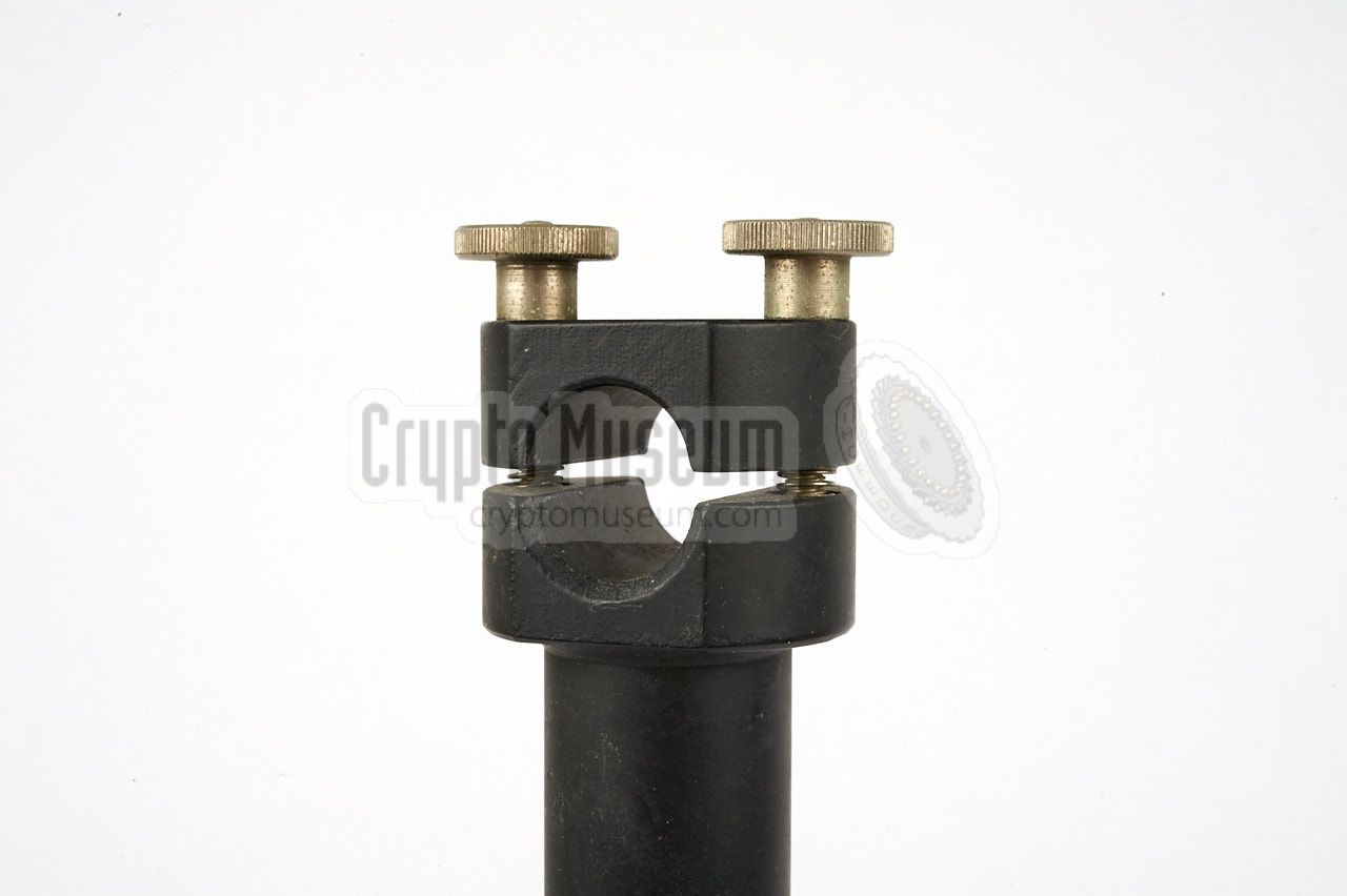
In the images above it is shown in the horizontal position, but this could
easily be changed to the vertical position by loosening the mounting head
of the short mast and rotating the boom.
The short aluminium mast was intended for fitting the antenna
onto a regular photographic tripod.
Before the antenna can be used, it should be adjusted to the frequency of
the transmitter, in order to obtain an appropriate gain. This is done by
removing the adjustable antenna elements and placing them on the frequency
table that is printed in white at the rear side of the reflector.
|
|
|
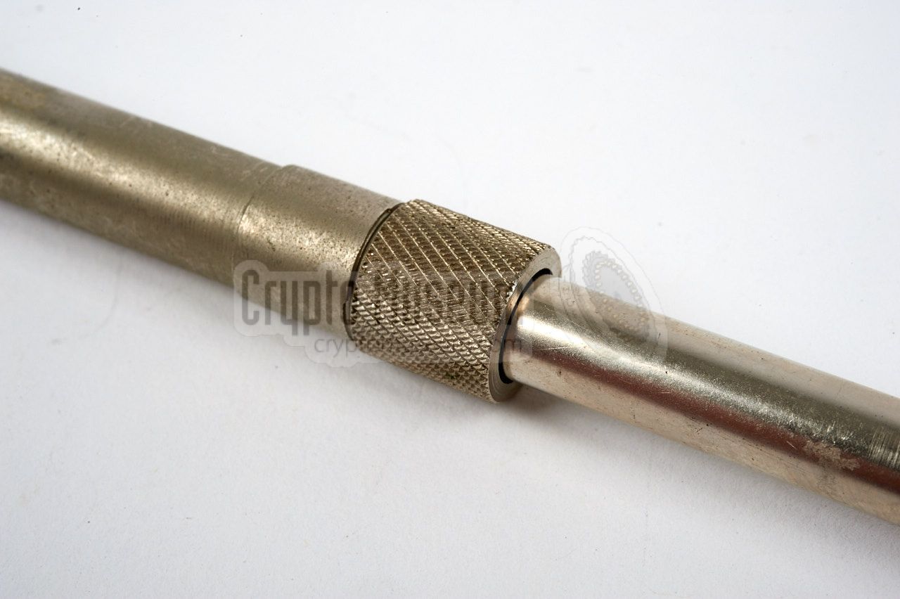
Both antenna elements are telescopic
and consist of two parts with a compression coupling at the centre.
After loosening the coupling, the inner part can be
shifted in or out, thereby changing the total length of the element. Once
the correct length is found, the coupling is tightened again.
|
Different length
telescopic antenna elements were available, both
longer and shorter, to allow the frequency range to be extended somewhat.
This effectively converts the SRN-9L featured on this page,
into the more universal SRN-9.
Installing an antenna in a concealed listening post (LP), always requires
some improvisation. For situations were a photographic tripod could not be
used, a modified vise was supplied, as shown in the image on the right.
It has a fitting for the antenna boom and can be attached to an arbitrary
object, such as a table or window pane.
|
|
|
Once the installation was completed, the SRN-9 was connected to the
surveillance receiver, which was usually an
SRR-52,
SRR-56,
SRR-90
or SRR-91.
It could also be used, of course, with any other
surveillance receiver
that operates in the supported 240 - 470 MHz frequency range.
|
|
The SRN-9 was recommended for use with the following receivers:
|
|
|
|
Any links shown in red are currently unavailable.
If you like the information on this website, why not make a donation?
© Crypto Museum. Created: Sunday 09 April 2017. Last changed: Tuesday, 20 February 2024 - 08:32 CET.
|
 |

|
|
|