|
|
|
|
|

|
|
CIA NRP EC SRN-58 →
Initially, the NRP would only develop the Sleevex antennas,
and pass the baseline
documentation of the design on to the CIA, so that it could be produced by an
alternative contractor in the US.
After several failed attempts however, the CIA returned to the NRP with an
order for many hundreds of them. They were used with covert transmitters
(bugs) operating in the 315 MHz band, such as the NRP-supplied
SRT-52 and
SRT-56,
but also with transmitters from other manufacturers.
Sleevex antennas for 316 MHz were also
used with the URS-1 survey system.
|
|
|
|
In most bugging operations, the Sleevex antenna had to be hidden inside
a building or inside a piece of furniture. This was commonly done in a
pre-drilled 3/8" hole that had been made by an external party. As the time
to place the bug and the antenna was limited, they had to ensure that each
Sleevex antenna fitted the a 3/8" hole. For this reason, all Sleevex
antennas that were made at the NRP, were first tested in a
reference hole of the prescribed diameter at the NRP site [3].
|
The diagram below shows a cross section of the antenna in horizontal position.
The antenna is basically a ½λ vertical dipole, of which the length of
both elements has been modified in order to compensate for the diëlectric
effects (εr) of the
medium in which the antenna is placed
(free air, concrete or wood), the frequency, the impedance, the velocity factor
of the coax, the diameter, etc. The basic principles of this antenna are
similar to that of the SRN-58 plexiglass antenna.
Sleevex antennas are constructed from a rigid piece of thick coax, of which
the central conductor has been replaced by a thin coax, as shown in the
diagram above.
At the feedpoint, the braided conductor (shield) is cut. Furthermore,
a hole is made through which the shield of the thin coax can be
reached. It is connected to the braided shield that forms the lower
element of the dipole.
The diagram above shows an enlarged cross section of the feedpoint
of the antenna. After removing the core conductor of the original (thick) coax,
the hole was enlarged with a very long drill, to make room for the new coaxial
feed line. The braiding of the feed line ends at the feedpoint, where it is
connected to the braiding of the lower element in the cut-away area.
|
|
|
Off-center-fed dipole
OCFD
|
|
|
Note that the feedpoint of the antenna is not precisely at the centre of
the dipole. The reason for this is that the arm through with the coax line
is fed, acts as a choke or balun for the asymmetric feed line.
The length of the balun is affected by the dielectric constant
(εr) of the material inside,
as a result of which it must be shorted by a factor of ~ 1.5 (i.e. × 0.66).
This is compensated by making the other arm of the dipole longer,
so that the total length of the dipole remains equal.
|
|
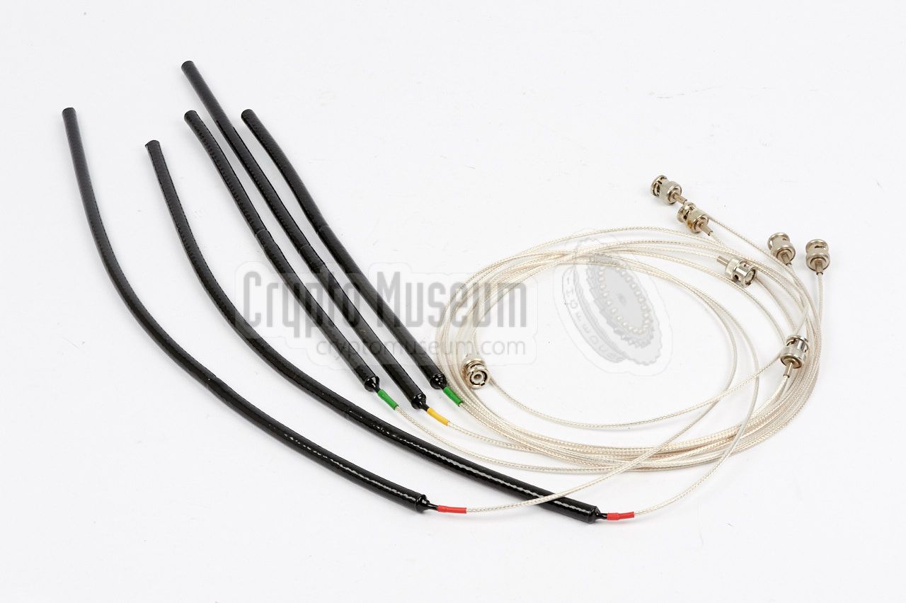
Sleevex antennas were available in the following band variants:
|
| Band | Frequency | Colour | Remark |
|
|
| 0 | 230 - 260 MHz | ? | e.g. SRT-57 |
| 1 (L) | 260 - 288 MHz | Blue | e.g. SRT-52 |
| 1 (H) | 288 - 320 MHz | Red | e.g. URS-1 |
| 2 (L) | 320 - 350 MHz | Green | e.g. SRT-56 |
| 2 (H) | 350 - 390 MHz | Yellow | e.g. SRT-56-F |
| 3 (L) | 380 - 425 MHz | Grey | |
| 3 (H) | 425 - 470 MHz | Black | |
| X | 1100 MHz | ? | |
|
|
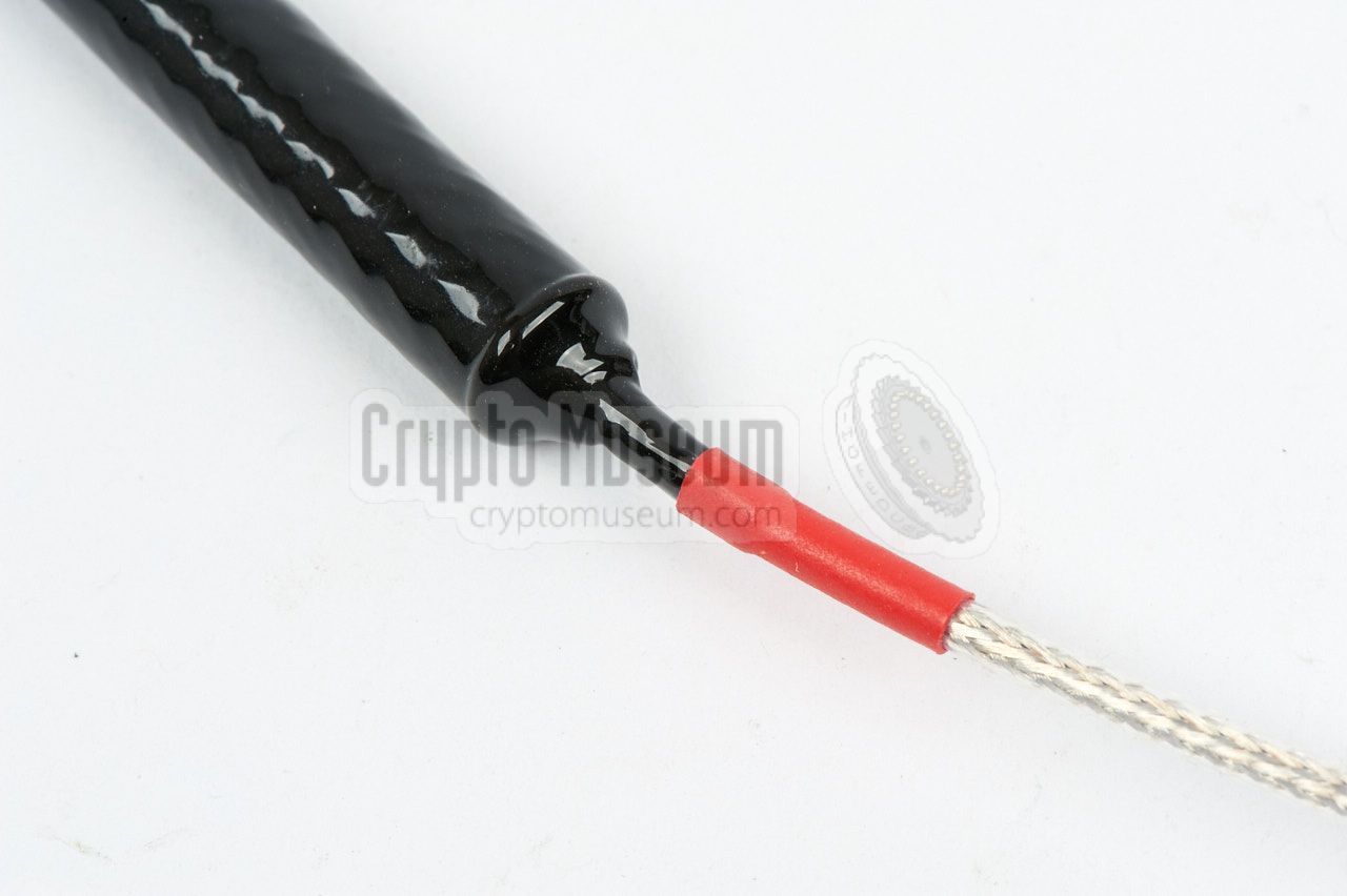
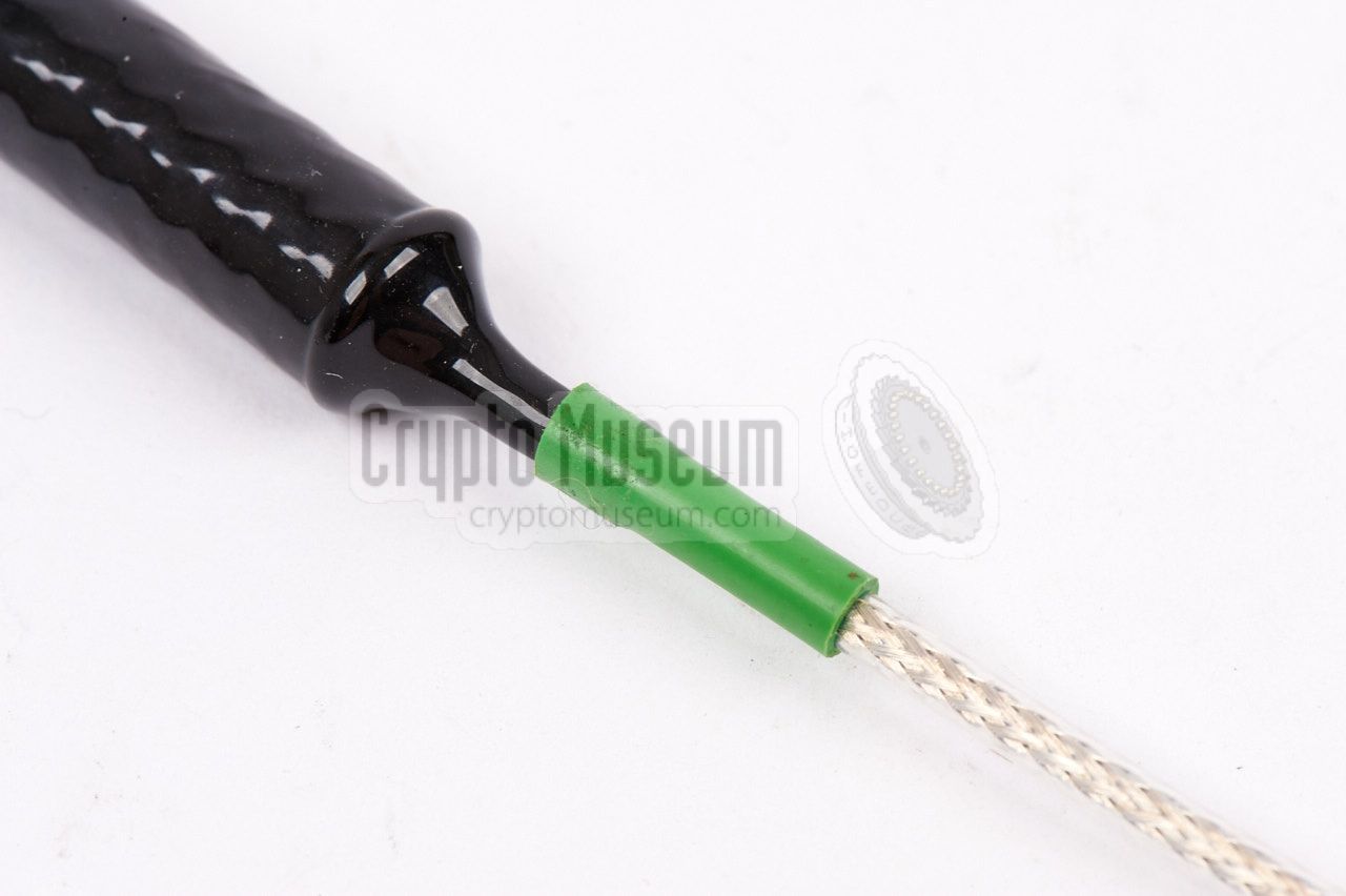
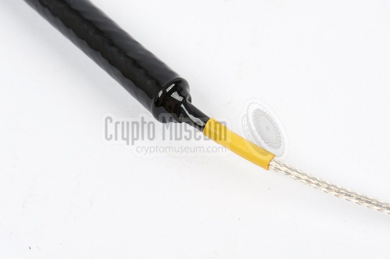
The coloured ring at the antenna base specifies the medium for which
the antenna is designed:
|
| Colour | εr | Material |
|
|
| Red | 1 | Free air |
| Yellow | 2 | Most woods, light building material |
| Green | 4 | Concrete, heavy building materials |
|
Generally speaking, the denser the material, the higher the diëlectric
constant (εr) and the shorter the antenna. The longest
of the three antennas (red) is for use in free air
(εr = 1).
➤ Dielectric constants of various materials
|
Sleevex antennas were made from a piece of thick rigid coaxial cable of which
the outer shield was cut roughly in the middle. The inner conductor was removed
at the centre hole was drilled out until the middle, in order to fit the thin
teflon coax feed cable. After mounting the cable, as indicated in the diagram
above, both ends were potted in a two-component epoxy.
After that, a shrink sleeve was fitted around the antenna. The heating device
shown on the right was used to shrink the sleeve.
|
|
|
In order to determine the link budget 1 of a given transmission system,
the NRP developed the special URS-1 survey system,
that was used by the CIA
to test the performance of the Sleevex antennas under varying circumstances.
The Universal Radio Set URS-1 consisted of an URR-1 receiver, two URT-1
transmitters and a range of accessories, and was supplied in an executive
style Samsonite briefcase.
➤ More information
|
|
|
-
In a telecommunications system, the link budget is the sum of all gains
and losses from transmitter, through the medium to the receiver.
➤ Wikipedia
|
The principle of the coaxial antenna was used again several
years later with the plexiglass SRN-58 antenna,
that was used for 1500 MHz bugs
like the SRT-107.
The SRN-58 was housed inside a perspex stick
in order to reduce the dielectric effects of the environment.
The SRN-58 had the same diameter as the transmitter (approx. 25 mm)
so that it could be fitted in a 1 1/8" hole.
➤ More information
|
|
|
|
|
|
Any links shown in red are currently unavailable.
If you like the information on this website, why not make a donation?
© Crypto Museum. Created: Thursday 05 January 2017. Last changed: Tuesday, 22 November 2022 - 11:03 CET.
|
 |

|
|
|
| |