|
|
|
|
|

|
|
Bugs Stasi Bodil B1 →
Passive carrier bug receiver
BODIL (Bulgarian: Бодил) 1 was a
Cold War
covert listening system (bug)
for room surveillance, developed around 1978 in Bulgaria, at a time when the
country was part of the Warsaw Pact. 2
The system consists of a BODIL-B1 transmitter and a matching
BODIL-B2 receiver, and uses an existing line for the transport of its
intelligence, using a 60 kHz carrier frequency.
In addition, the B1 transmitter is powered remotely 3 by the receiver.
In Stasi
terminology, the device is known as a TF-B Sender,
in which TF
means Träger Frequenz
(carrier frequency) and B refers
to B-Technik
(B technology): acoustic room monitoring (bugging).
The BODIL-B2 receiver is described below.
|
Although the device is suitable for virtually any kind of line, its
preferred use was over telephone lines inside hotels, strategic companies
and 'special objects'. In those situations, Bodil-B2 was simply connected in
parallel with the line.
At the target area (i.e. the object) the Bodil-B1 transmitter was connected
in parallel with the telephone set, in such a way that it could pickup any
sound in the room. Unlike most other wired bugs, the B1 transmitter was
not powered by the voltage on the line, but rather by a 30 kHz signal
that was injected into the line by the B2 receiver.
|
|
|
As the system uses phase modulation (PM) for the transport of its intelligence,
it is insensitive to line damping. Furthermore, it is remotely powered,
which reduces the chance of detection.
The image above shows the Bodil-B2 receiver. It measures 29 x 24 x 7.5 cm
and weighs 3000 grams. The intercepted sound can be monitored directly
from the receiver by means of a pair of headphones, or recorded on a
(tape) recorder. In most cases through, the output from the receiver was
forwarded to a Stasi monitoring station, via a leased telephone line
(German: PO-Leitung).
The receiver can be powered in various ways: either from the local mains, a
local set of 12V DC batteries, or from the leased line. In addition, it could
be controlled remotely – via the telephone line – using an external remote
control unit. Bodil was developed in Bulgaria around 1978 and was in
production for approx. 10 years.
Judging from the date codes on the components inside the device
featured here, it was made around 1985.
Bodil-B2 was also used by the
state security service
– Stasi
or MfS –
of the former DDR (East-Germany),
where it was designated 33343-2.
|
 |
-
Бодил (Bodil) is the Bulgarian word for Thorn.
-
In its capacity as a highly-developed technological country,
Bulgaria was often referred to as the Silicon Valley of the
Eastern Bloc at the time [3].
-
This means that the transmitter can be categorised
as a Passive Element, meaning that it does not have a direct local
energy souce. Instead, it is powered by energy provided by a signal
from the listening post.
|
The diagram below shows the front panel of the Bodil-B2 receiver.
All connections to the lines and any recording or monitoring
equipment are at the front panel. The only connections that are at the rear
are for the mains (suitable for the 220V AC mains only) and for
an external 12V DC battery. For testing, each B2 receiver was supplied with a
B1 transmitter
on a short piece of wire, that could be connected straight to the
input socket marked ЛИНИЯ (line) at the B2's front panel.
Installing and operating the B1 transmitter and the B2 receiver is
straightforward and requires only limited knowledge of bugging devices.
The full instructions are avaialable for download in Bulgarian [A]
and German [D]. From left to right, the following controls and sockets
are available:
|
- Power indicator (LED)
- 3-position power switch: off, remote power, local power
- Remote control (via second tone transmitter) when depressed
- Subscriber line
- PSTN (not used in most situations)
- Leased line to central monitoring station
- 30 kHz power level (adjust for minimum audio distortion)
- Headphones audio level
- Line output for recorder
- Headphones socket
|
- Modulation not dependent on distance (damping)
- No local power needed for transmitter
- Low compromising risk
|
- Hotels, with and without remote control of the bug
- Companies and institutions with a local PABX (German: GWN-Alage)
- Building with a central antenna system
- ...
|
Depending on the circumstances, the BODIL system could be used in two ways.
The preferred use was inside hotels and 'special objects' which in most
cases had a local house exchange (PABX) or a special monitoring room.
In such situations, the subscriber line was alread isolated
from the public switched telephone network (PSTN) and Bodil-B2 could be connected
in parallel to the line:
In this situation, the subscriber line is used as normal and Bodil-B2
provides power to the Bodil-B1 transmitter via a strong 30 kHz signal
that it superimposes onto the line. The B1 doubles this frequency and
returns a 60 kHz phase-modulated (PM) signal,
that is then filtered and decoded in the B2.
The decoded audio can be monitored or recorded locally, but it could also
be relayed to a central monitoring station via a so-called leased line,
in German known as a PO-Leitung. The maximum distance between the transmitter (B1)
and the receiver (B2) is approx. 800 metres.
In situations were no local PABX is available and the subscriber line is
connected directly to the Public Switched Telephone Network (PSTN), the
subscriber line has to be cut and the receiver is inserted between the telephone
set and the exchange. In this case, the ATC (АТЦ) socket at the front
panel is used for connection to the exchange. This method was not frequently
used though.
The security service of the former DDR (East Germany)
– the Stasi – also used the
central antenna installation (CAI) of an appartment building as the
transport medium for BODIL. Especially for this application, a
transformer-based modification
was suggested, that allowed the B1 bug
and the B2 receiver to be connected directly to the coaxial cable of the
central antenna system [C]. In such cases
the bug was usually placed inside or near the antenna wall socket
of the TV/radio set.
|
The receiver - BODIL B2 or 33343-2, is the core device of the installation.
It provides power to the B1 bug and remotely activates it. It also contains
a PM demodulator that converts the phase-modulated signal from the bug into
an audible signal again. It is described above.
The receiver can not be used with other types of wires carrier bugs.
It is the only receiver that is suitable for the reception of the B1 bug.
|
|
|
To check the functionality of the receiver, a complete and functional B1
transmitter – wired to a suitable 7-pin plug – is supplied with each B2
receiver. This test bug should be connected to the leftmost line socket
(marked ЛИНИЯ).
After connecting the bug, the 30 kHz level (G) must be adjusted for
minimum audio distortion. Once satisfied, the test bug is removed and the
subscriber line is connected to the socket. The level (G) then has to be
adjusted again.
|
|
|
The receiver has three 7-pin USSR-style sockets at its front panel,
for connection of the lines. The line socket (ЛИНИЯ)
is always used, as it must be connected to the subscriber (i.e. the line
under surveillance). The other sockets are optional.
All three sockets have the same pinout.
the image on the right shows a suitable line cable with banana plugs and
crocodile clips.
|
|
|
- Power switch in the upper position (local power)
- Remote control button (ДК) not depressed
- Connect subscriber line (with Bodil-B1) to socket (1)
- Adjust 'Level' for undistorted audio signal
|
- Local AC mains network (220V AC)
- Local 12V DC battery (connected at the rear)
- From exchange (local power)
- From leased line (remote power) (25 mA)
|
- Remote control button (ДК) depressed
- Inject 4-10 mA into the line
|
- Power switch in the middle position (remote power)
- Inject 25 mA via the leased line (PO-Leitung)
|
The receiver is connected directly to the subscriber line,
as shown at the bottom of the block diagram below.
At the left is the 30 kHz generator that
delivers the activation signal for the bug. The returned modulated 60 kHz signal
is filtered, demodulated, amplified, filtered again and compressed,
and is then fed to the headphones and/or a recorder.
Alternatively, the signal can also be delivered directly to an external
state security listening post via a leased line. The receiver can be
powered from the mains, by internal batteries, or from the (optional) leased
line.
The block diagram below shows how the transmitter works. At the far right is
the telephone line from which the 30 kHz activation signal is received
(sent by the receiver). This signal is filtered and then rectified,
creating just enough DC voltage to power the circuit and the microphone.
The 30 kHz is also doubled to 60 kHz and fed to the modulator, where
the amplified sound from the microphone is added, resulting in a
phase-modulated 60 kHz carrier signal that is injected into the
telephone line. The 30 kHz and the 60 kHz signals are way above the
audible range, so that they can pass the cable unnoticed. Yet they are
sufficiently low to pass the existing cables and junction boxes,
especially if the distance between transmitter and receiver is not too large.
➤ More about the Bodil-B1 transmitter
|
|
The receiver is housed in an universal aluminium enclosure 1
consisting of a strong
frame with two (blue coated) aluminium case shells, each of which is held
in place by two recessed screws. After removing the recessed screws, the
case shells can be taken off and the interior is exposed.
|
Inside the device are four printed circuit boards (PCBs), mounted to
the frame roughly in the middle, with the components visible from the
top of the device.
At the bottom, the solder side of the PCBs is
visible, along with the 220V mains transformer
and an additional line filter,
which was known as ТОПОЛА (TOPOLA = magnolia).
At the front left is the power supply unit (PSU) with provides three
internal voltages, two of which are stabilized. It gets its power from
the mains transformer at the bottom, an external 12V battery,
or via the leased line (when used).
|
|
|
|
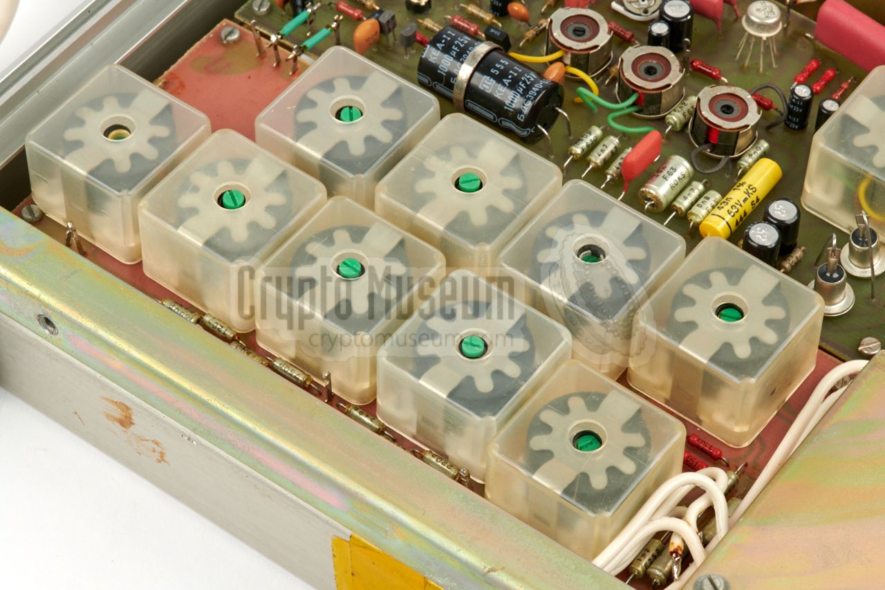
At the rear left is the
30 kHz sine-wave generator that delivers the
power for the BODIL-B1 bug which is connected in parallel to the
subscriber line. The 30 kHz generator board is shown in the image above.
This PCB is normally shielded to avoid
interference with the PSU and other circuits.
|
At the rear right is a large circuit board that holds a
high-quality 60 kHz band-pass filter and transformers for
connecting the subscriber line (in parallel to the 30 kHz generator).
The output of the filter board is passed to the demodulator / audio
board, which is located at the front right.
The demodulator board has the same size as the filter board, but is
the most densely populated of the four boards. It holds a three-stage
amplifier-limiter, followed by an FM/PM demodulator, built around
an RCA
CD4046 phase-locked loop (PLL) integrated circuit (IC) — here
visible at the top.
|
|
|
|
The output from the CD4046 is passed through a 5 kHz low-pass filter –
so that only the speech spectrum remains – and then
amplified and compressed in a small hybrid circuit, which is cast
in a red compound. The compressor output is amplified for the
headphones and for the leased line, using UA741 ICs.
The large coil at the right in the above picture, is the leased
line transformer.
|
-
The enclosure is very similar to the one used with the
Chech intercept receiver Přístroj,
and was apparently a universal product in the former Eastern Block
countries.
|
|
When we acquired our BODIL B2 receiver, not much was needed in terms of
restoration. It had pencil-written translations in German on its front
panel, which were likely not put there by the original owner: the Stasi.
We have carefully removed the text from the front panel with a solvent.
|
The only problem – if you can call it that – was that the device did not
always power up when the three-position power switch (A) was placed in the
upper position. The reason for this was that the front panel was mounted
to the frame a few millimetres too low, and was therefore partly blocking
the power switch. This was solved by removing the cover and refitting
the front panel.
Apart from this, the receiver worked straight away without any glitches,
which is mainly due to the high manufacturing standards and the fact that
only first-class components were used.
|
|
|
Connecting a BODIL-B1 transmitter to the
line socket (ЛИНИЯ) required only the 30 kHz level (G) to be adjusted in order
to obtain a noise-free distortion-free signal through the headphones.
We assembled several line cables
for testing the device on a local analogue POTS telephone line.
|
The receiver is extremely well designed and built, with well-selected
components and a good sense of high-quality filtering. Below is the circuit
diagram of the device, which has been split into a number of sub-circuits,
in line with the block diagram
and the original circuit diagrams [A].
The first sub-circuit is the line filter PCB.
It contains the line transformer which is connected directly to the
subscriber line (a/b) and a multi-section 60 kHz
bandpass filter for extracting the signal from the bug.
An additional filter (shown in yellow in the diagram below) is mounted at
the bottom of the unit.
It is only used when connecting the receiver to an
external exchange (a'/b').
The next circuit is the 30 kHz generator,
which provides the activiation signal and the power for the actual bug
(i.e. the Bodil-B1 transmitter).
The circuit is housed in a shielded enclosure
in the corner of the unit,
and is built around six BC107 transistors. At the left is the
crystal-controlled
sine-wave oscillator from which an adjustable level is
supplied to an amplifier, or booster. The output from the booster is then
injected into the subscriber line via the
transformer at the right.
The output of the filter board
(at the top of this section) provides the
input for the demodulator board,
which is located immediately behind the front panel of the unit.
The signal is first passed through a 3-stage
amplifier/limiter – built around BC107 transistors – and then fed to a
CD4046 phased-locked loop
(PLL) circuit, made by the western manfuacturer
RCA
[E]. It
demodulates the phase-modulated signal and recovers the original
audio, which is available at the bottom right.
The buffered signal from the demodulator is now passed through a 5 kHz
low-pass filter and is then applied to the input of an amplifier/compressor,
which in this case is a small hybrid circuit. The output from the audio
compressor is available as a fixed-level recording output on the
front of the device.
It is also passed to the headphones amplifier (at the bottom left) and to a
separate amplifier that provides the coupling to the (optional) leased line
(visible at the bottom right).
Both the headphones amplifier and the leased line amplifier, are built
around the well-known UA741 operational amplifier (op-amp).
The headphones level can
be adjusted with the volume control at the front panel,
whilst the leased line amplifier is internally adjusted at a
fixed level. Note that the line transformer at the bottom right
has two diodes that are used when the device is remote-powered
(via the leased line). These terminals
are connected to the power supply unit.
Above is the circuit diagram of the power supply unit (PSU).
It consists of a small PCB – located at the
front left of the device – and a
small transformer
at the bottom. The PSU delivers a raw
10V DC plus two stabilized voltages. At the left are the connections
for the mains AC network, and for an external 12V DC source. At the
top right is the (optional) power supply from the leased line.
|
Carrier 60 kHz Modulation PM (phase modulation) Mains 220V AC +10%/-20% Battery 12V DC ± 1V (external) Current ≤ 40 mA when powered from the mains Current ≤ 40 mA when powered by a 12V battery Current 25 mA when powered from a leased line Impedance ЛИНИЯ (LINE) 150Ω Damping ≥ 4dB Recording 250 kΩ, 100mV ± 3dB Leased line 600 kΩ, 500mW ± 2dB Distortion 1000 Hz ≤ 6%, 5000 Hz ≤ 3% Noise ≤ 800µV (recording) Dimensions 290 x 240 x 75 mm Weight 3000 grams
|
|
GWN
|
|
Großwählnebenstelle
German expression for a local Private Automatic Branch Exchange (PABX).
|
|
PO
|
|
Postmietleitung im Ortsnetz
Local leased telephone line.
|
|
POTS
|
|
Plain Old Telephone System
Common expression for an old analogue telephone network, based on twisted pair
copper wiring and electromechanically or electronically switched subscriber
lines, with analogue signalling and pulse or tone (DTMF) dialling.
Also known as Plain Old Telephone Service.
|
|
PSTN
|
|
Public Switched Telephone Networks
Common expression for an automated switched telephone network –
which can be analogue as well as digital –
for exchanging telephone calls between subscribers.
|
|
|
Telephone line
ЛИНИЯ - АТЦ - ЦЕНТЪР
|
|
|
|
The Bodil B2 receiver has three sockets for connection of telephone lines
at its front panel: ЛИНИА for connection of the subscriber line
(with the B1 transmitter connected in parallel to the telephone set),
АТЦ for connection to the exchange 1 , and
ЦЕНТЪР (center) for the (optional) leased line to a
Stasi monitoring station (CEKO).
|
|
|
-
Not used in most situations.
|
- Line out
- GND
- Line out
- not connected
- not connected
|
|
- БОДИЛ Б (BODIL B), Technical manual and operating instructions
Bulgaria, 1979. Original manual in Bulgarian/Russian language.
BStU, 21 pages marked BStU 0178—0199. 1
- Bodil, Beschreibung
DDR, date unknown. Hand-written description (German).
BStU, 10 pages, marked BStU 0223—0232. 1
- Bodil Anpassung, Beschreibung des Vorslages
Hauptmann Bräunig, Suggested modification (German).
Date unknown. BStU, 2 pages marked BStU 0221-0222. 1
- Information Linie B, Nr. 1/86. Kennblatt 'Bodil' 33343-1, 33343-2
Bodil technical specifications (German). January 1986. 6 pages marked BStU. 1
- Texas Instruments, CD4046 Datasheet
2003. Retrieved January 2014.
|
-
Document from BStU archives [2],
kindly supplied by Detlev Vreisleben [1].
|
-
Full name: Bundesbeauftragte für die Unterlagen des Staatssicherheitsdienstes
der ehemaligen Deutschen Demokratischen Republik
(DDR) —
Federal Commissioner for the Records of the
State Security Service
of the former German Democratic Republic (GDR) —
officially abbreviated to BStU.
|
|
|
|
Any links shown in red are currently unavailable.
If you like the information on this website, why not make a donation?
© Crypto Museum. Created: Wednesday 02 May 2018. Last changed: Wednesday, 05 November 2025 - 11:38 CET.
|
|

|
|
|