|
|
|
|
|

|
Spanish valve-based radio bug · 1953
Bicho 1 is a wireless radio frequency (RF)
covert listening device (bug), build with three thermionic valves
(vacuum tubes), developed in the early 1950s in Francoist Spain, probably for industrial or
political espionage, early in the Cold War, before Spain was
a member of the United Nations (UN).
|
The device produces approx. 150 mW of RF power at a frequency on or
near 6.865 MHz in the 40 metre band, using amplitude modulation (AM).
It was commonly used in combination with an externally connected carbon
microphone.
The bare device measures 115 x 70 x 26 mm and weighs just 210 grams.
It is powered by 1.4V (LT) and 90V (HT), that were supplied by an
external LT/HT battery pack or – more likely – an external 220V
AC mains power supply unit (PSU).
With a properly installed (wire) antenna, the device has a range of
several hundred metres.
|
|
|
|
The device is built with parts from various European countries
but has a spanish signature, most notably the
wiring layout that is taped to the enclosure.
The device shown here was discovered in 1990 by construction workers in
the French customs office (douane) of Le Perthus, just south of Perpignan
(France), when the border with Spain was being converted into an EU
internal one [1].
|
It is likely that it had been planted there in the early or mid-1950s,
when the French customs office was built or refurbished.
Perpignan is the southmost major French city before the Spanish border.
In the days before the A9 autoroute, the
main road from south-east France to Barcelona
crossed the Spanish border in the small town of Le Perthus into El Pertús
on the Spanish side [5].
The device had just enough RF power to reach the Spanish customs office
about 300 metres to the south, at the other side of the border, where the
listening post (LP) was most likely located.
|
|
|
|
When it was discovered, the wires were cut-off by the construction workers,
who probably had no idea what they had found. As far as we know,
the accompanying power supply unit (PSU) and the original microphone have
not survived. Judging from the construction of the enclosure and its
interior, it was not a one-off, but was probably part of a small
– professionally produced – series.
|
-
As the actual name or designator of this device is currently unknown,
we have nicknamed it BICHO (pronounced: bi-choh), which is Spanish for
bug, software error or hidden microphone.
|
The image below shows the features of the (partly reconstructed) listening
device. The actual bug – nicknamed EL BICHO – is at the centre. At the right
is a piece of wire that acts as the antenna. It can be hidden inside a wall or
behind a ceiling.
At the bottom left are the power wires, which should be
connected to a 1.4V/90V power source, such as a battery or a mains PSU
(not shown).
At the top left is the microphone, which is connected to the device by
means of a shielded cable, in order to avoid picking up the 50 Hz hum from
the power lines in the building. Judging from the circuit diagram,
the device was used with a carbon microphone, such as the one shown here.
|
Below is the circuit diagram taken down from the actual device in
our collection. It is built around three thermionic valves (vacuum
tubes) and comprises a microphone pre-amplifier (V1), an AM
modulator (V2) and an RF oscillator (V3). The latter is driven
by a 6865 kHz quarz crystal (X1).
At the left is the audio pre-amplifier (V1). Note the 300Ω
resistor (R1) between the microphone and the LT rail (+1.4V DC). This
suggests that the device was used with a carbon microphone. The output
of the amplifier (V1) is taken from the anode and supplied via C2 to
the input of the modulator valve (V2). At the far right is a crystal
oscillator built around a 3S4 (V3). It delivers an RF output of
approx. 150 mW to the antenna, via the tuned circuits at the top right
(L1/C5/C6).
As the power to the modulator (V2) and the
oscillator (V3) is supplied via L2
– which has a large inductance of several H –
the modulator will load the HT' rail in the
rythm of the sound from the pre-amplifier, causing the voltage on
the HT' rail to vary accordingly. As a result, the power to the
oscillator valve (V3) will vary as well, resulting in Amplitude
Modulation (AM) of the RF output.
Two capacitors, C7 and C8, were missing from the device when we received
it, but had clearly been present, as part of their legs and the solder
joints were still present. It is likely that they were destroyed when
the device was discovered and pulled away from the antenna wire, as they
were both mounted close to the antenna port. C8 decouples the HT' rail
for RF signals and improves the operation of the oscillator.
C7 is part of a series-resonance filter, together with L1c. When C7
was destroyed, the top-end terminal of L1c was broken off and had to be
reconstructed.
|
|
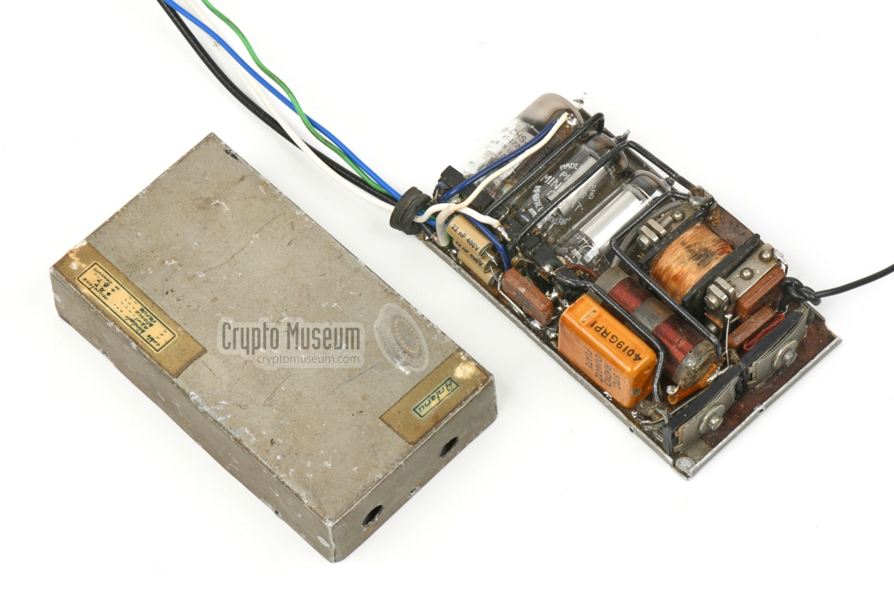
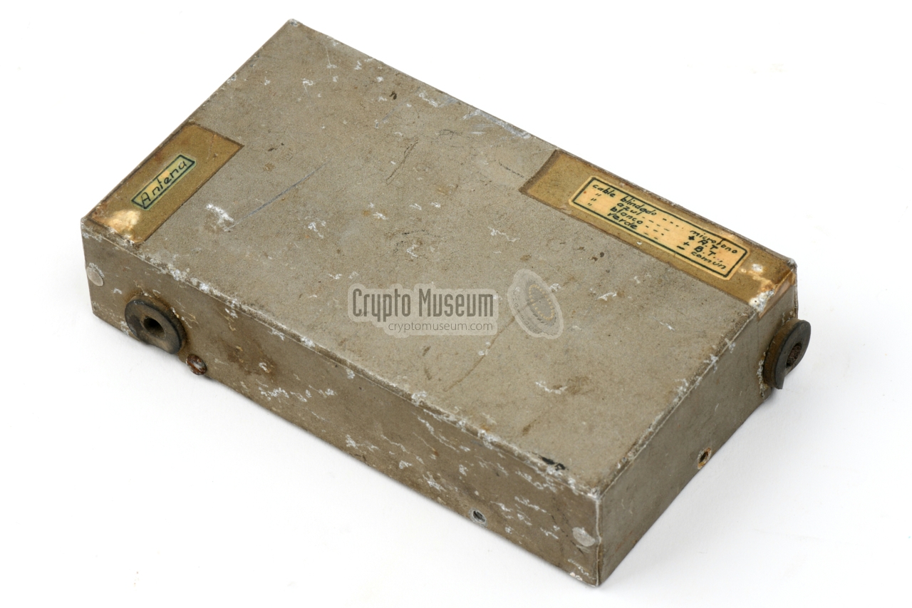
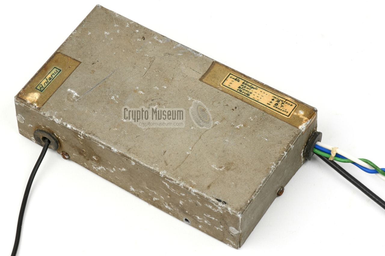
The bug is housed in a folded aluminium enclosure that consists of two
parts: a base to which all parts are mounted and a case shell at the top.
The case shell is bolted to the base by means of 6 screws divided over the four
sides. After removing these screws, the case shell can be taken off.
|
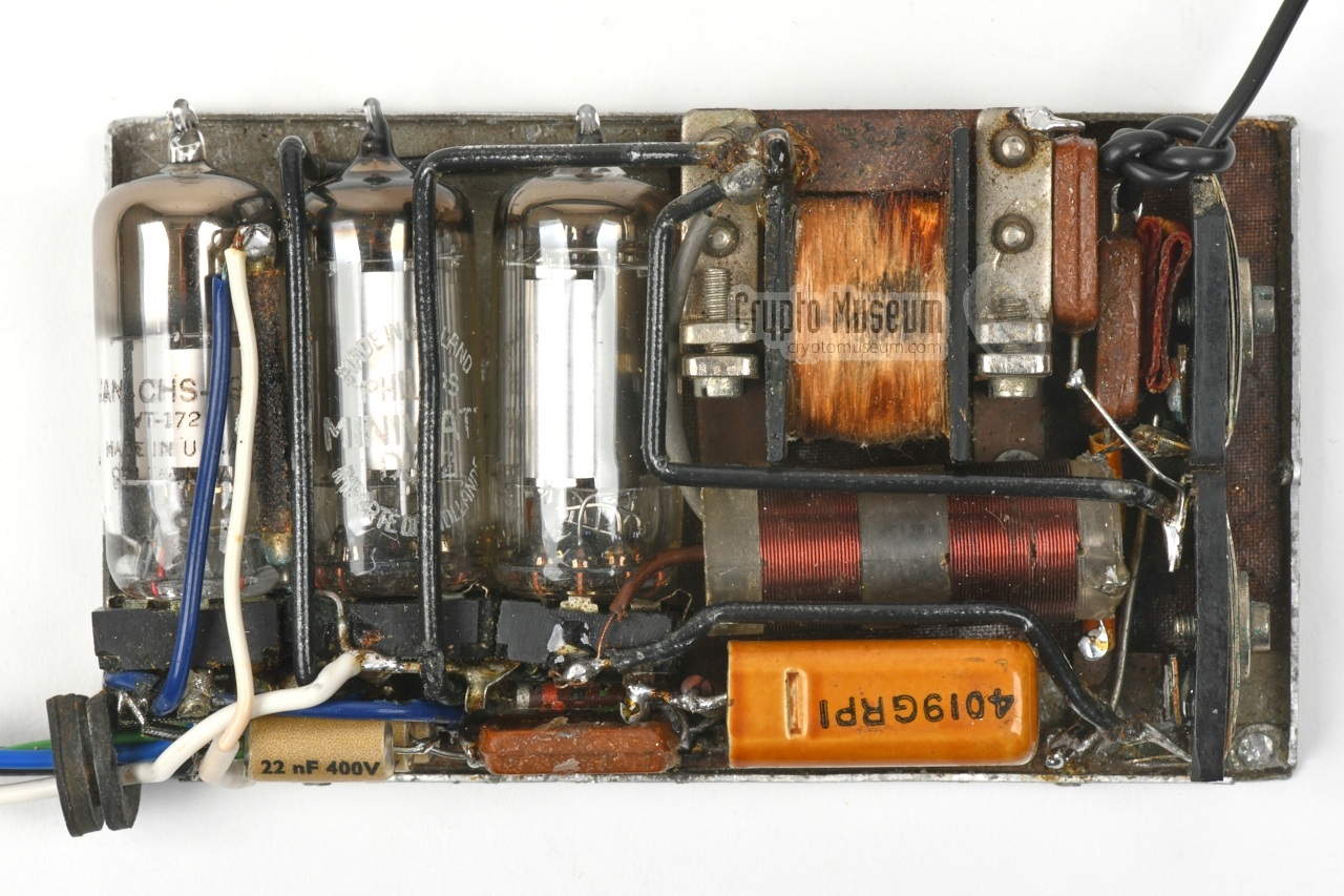
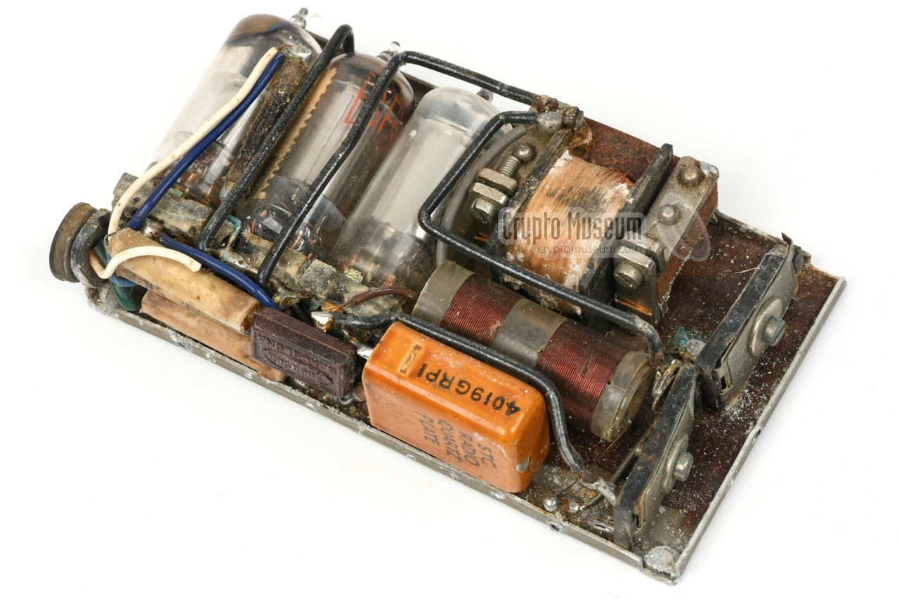
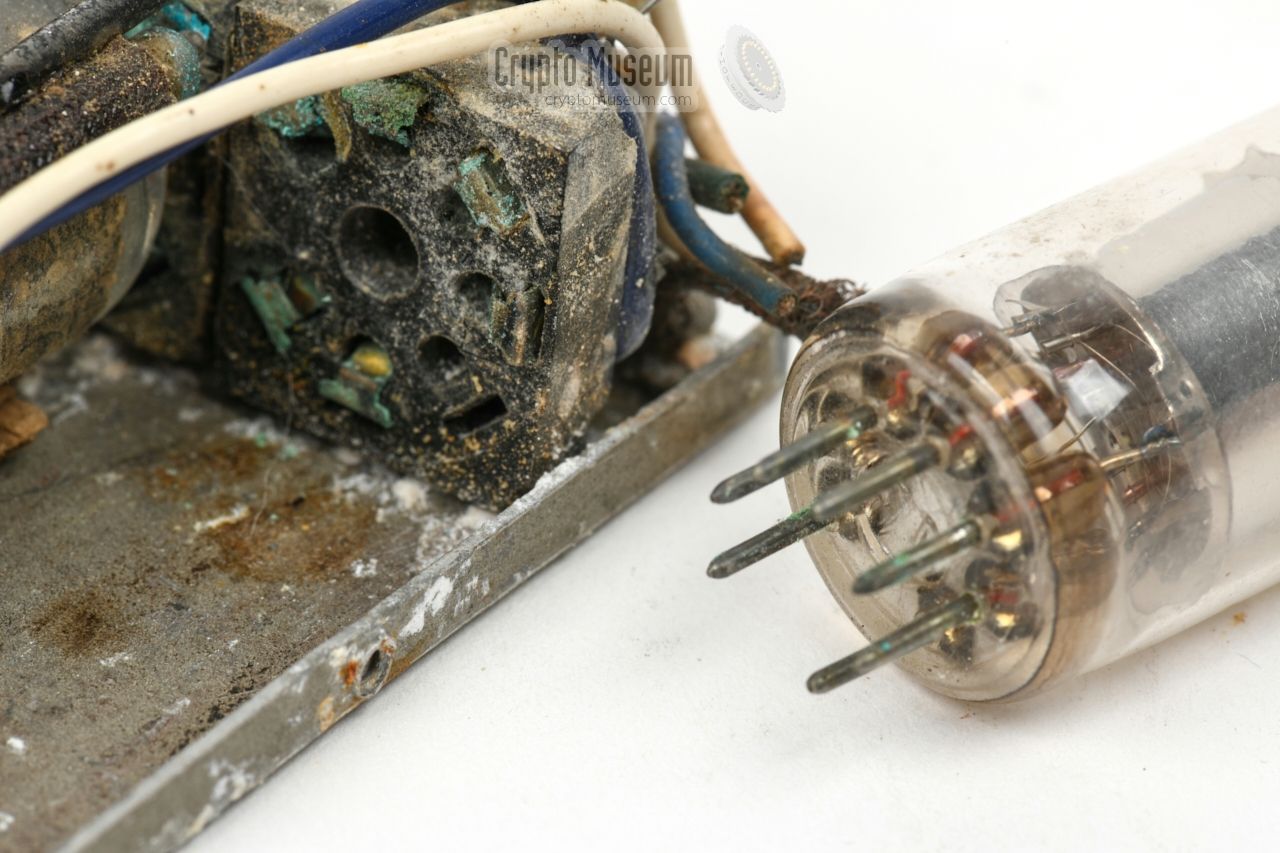
This reveals the interior of the bug, as shown in the image on the right.
The three sub-circuits are built around three thermionic valves (vacuum tubes)
that are located side-by-side in the left half of the device. They are
installed in square black sockets that we have not seen before.
The passive components (resistors, capacitors) are mounted directly to
the contacts of the valve sockets. The resistors are not directly visible,
as they are covered by the capacitors. The wiring from the outside
(LT/HT power
and microphone) enters the device in the bottom left corner.
|
|
|
|
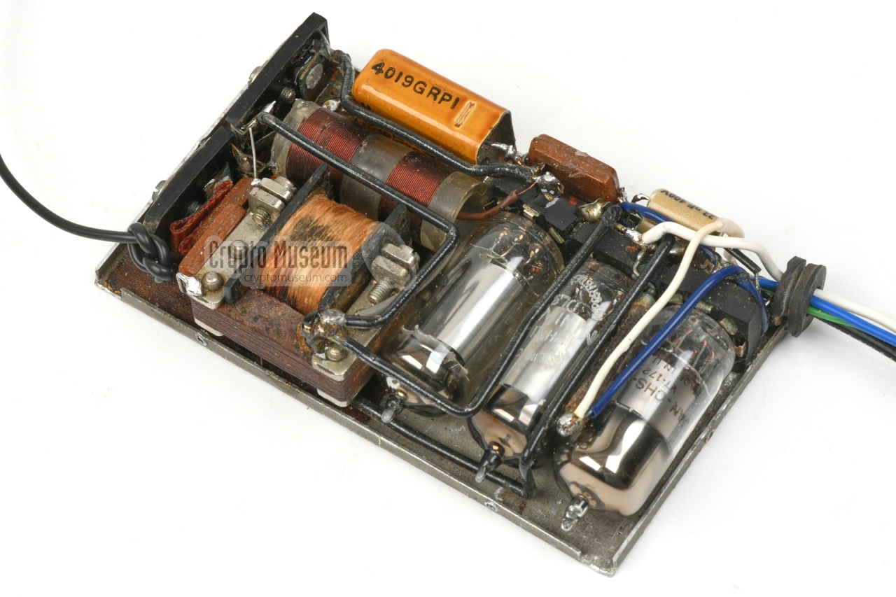
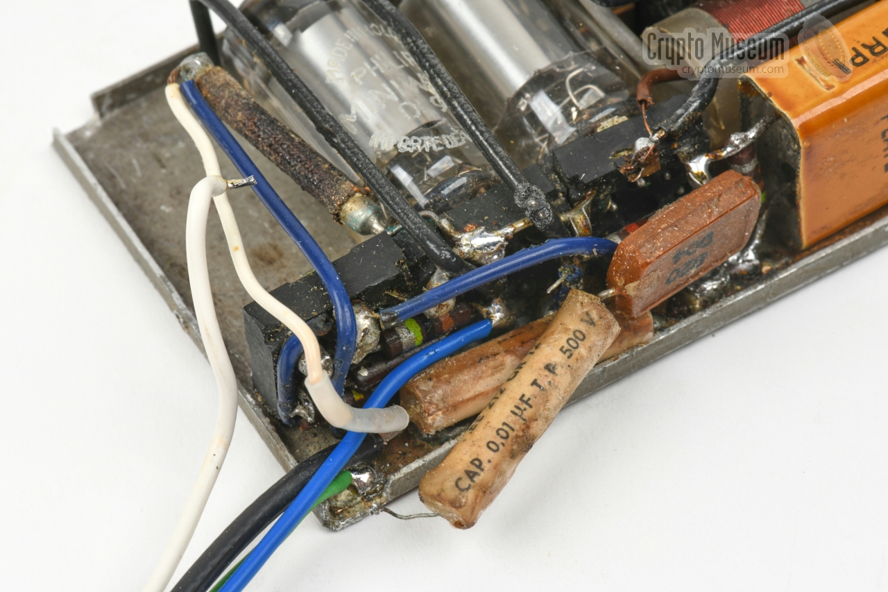
The right half of the device accomodates – from front to rear – a large
quartz crystal for the oscillator, the tuned circuit of the oscillator
combined with the antenna coil, and a relatively large choke coil. The
latter forms part of the AM modulator circuit.
At the far right are two trimmers that can be adjusted from the outside:
one for the oscillator circuit and one for the antenna. The antenna –
typically a 3 metre long piece of wire – leaves the device in the upper right
corner.
|
|
When the device featured on this page was discovered by construction
workers in 1990, it was already ~ 35 years old. It had probably been
installed covertly behind a wall or a ceiling in the mid-1950s and had
done its work for several years before it stopped producing intelligence.
|
It is unlikely that it was ever detected by French security, as in that case
the device would have been removed. The fact that it was still there in 1990,
indicates that it had probably died a few years after its installation. Either
the valves were worn out, or the power source had been cut off.
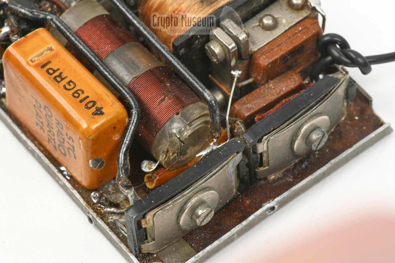
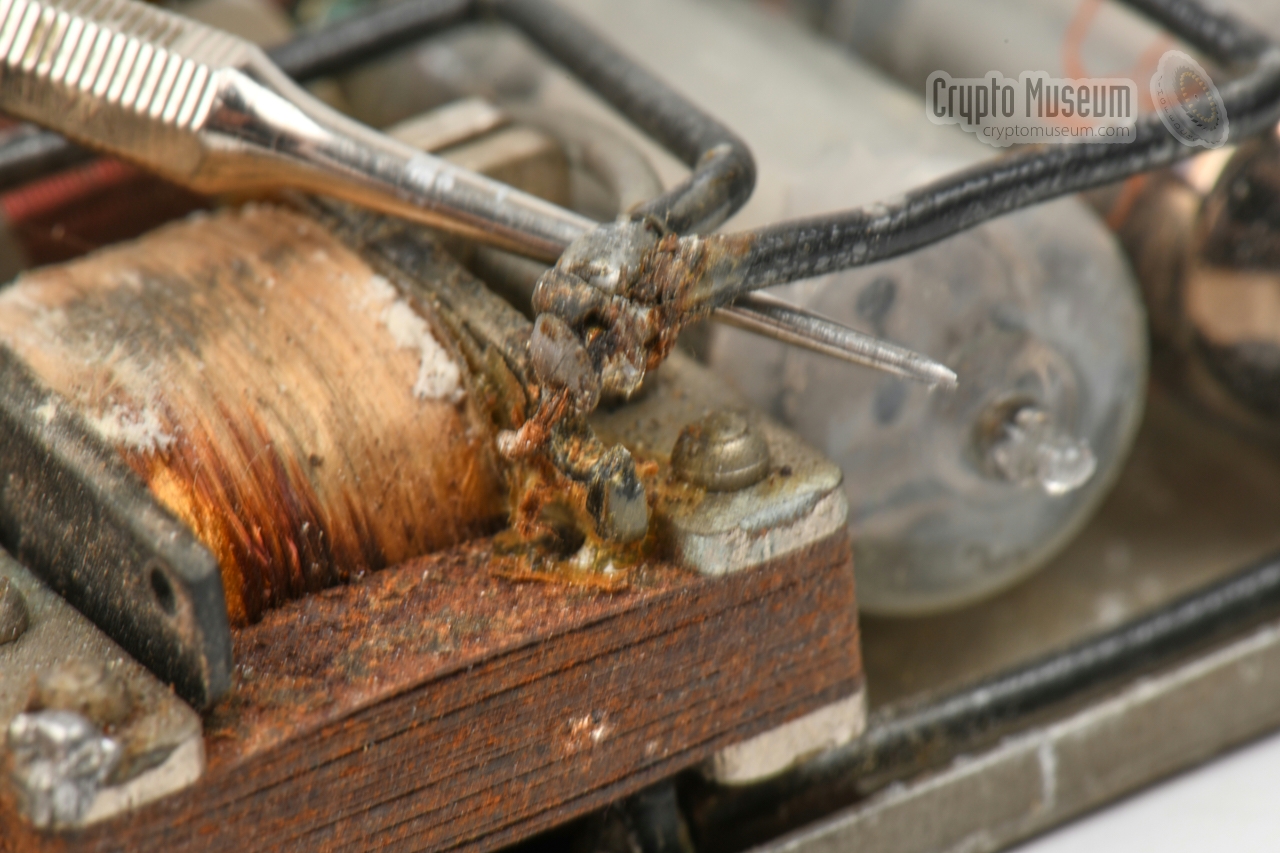
It is clear that before its discovery (and possibly also in the 30 years after
that), it was kept in a moisturous and dusty place. The enclosure and the
interior show severe signs of corrosion, and several solder joints and mounting
posts were broken, as can be seen in the image on the right.
|
|
|
|
It was therefore unlikely that, when we received the device in 2021, it
would still work. After the initial inspection, the valves were carefully
removed, so that the pins and the valve sockets could be cleaned. Next,
the broken mounting posts (C5, C6) and the broken solder joints were restored.
|
It was clear that some components were missing from the top right corner
of the device (between C6 and L2) and that the antenna-end of L2c was broken
off. This had probably happened when the device was discovered and
subsequently removed by the construction workers in 1990.
By carefully studying the remains of the lost parts, we were able to make
an educated guess of what had previously been located there. The broken (open) end
of L1c was restored and capacitors C7 and C8 were added. In the
circuit diagram
above, these parts are identified in red.
|
|
|
|
The cut-off wiring was restored and the original
valves were tested.
Although all three heated up, they drew less current than expected and none
of them showed any signs of emission. This was of course to be expected from
a device that had probably been on the air 24/7 for several years.
|
It was decided to replace the valves 1 one at a time, so that each sub-circuit
could be tested individually, starting with the oscillator (V3). As it did not
produce an RF signal, C5 and C6 were turned until it did. The oscillator
then produced a strong and stable signal at 6.865 MHz; the f1
or fundamental frequency of the quartz crystal. 2
Next, the modulator valve (V2) was inserted to see whether it could amplitude
modulate (AM) the oscillator. In doing so, it became clear that the 10 nF
coupling capacitor (C2) between V1 and V2 was broken. It has lost one of its legs.
|
|
|
The modulator (V2) worked, as a 50 Hz hum could be heared in the receiver when
the g1 of V2 was touched with a metal object.
Next, the microphone amplifier valve (V1) was replaced, but the room audio
from the microphone could not be heared through the receiver. As none of the
voltages on the pins of V1 were within
the expected range, it became clear
that the other two 10 nF capacitors also had to be replaced.
Once this was done, the wiring at the bottom of the valve sockets was
restored and the unit was tested again. This time it worked as expected.
|
|
|
|
As the amplifier circuit (V1) is dimensioned for a carbon microphone — the 300Ω
resistor (R1) provides a bias voltage — we decided to use the carbon microphone
from a telephone handset of the era, as this might indeed have been used with
the device. The choosen microphone picks up any sound in the room and produces
a crisp and clear audio signal in our
surveillance receiver.
|
-
The two 3S4 valves were replaced by the equivalent DL92. As the holes in the
valve sockets are too large, the legs of the valves were bended outwards, just
like it had been done with the original valves.
-
The f2 was down by 60dB and the f3 was down
by 40dB, so we assume that the device was used at the fundamental crystal
frequency of 6865 kHz.
-
These old composite resistors have an accuracy of 10% and are known to
degrade over time. It is therefore important to check whether they are
still within reasonable limits. This was indeed the case.
|
- Wires cut-off
- Several broken solder joints
- Broken contact terminal on RF choke
- Antenna trimmer broken
- Corrosion in various places
- Antenna tank coil broken
- Two capacitors missing
|
- Valve sockets (and valve contact pins) cleaned
- Broken contact terminal of choke coil repaired
- Broken antenna trimmer refitted
- Anode trimmer mechanically re-aligned
- External wiring restored
- Antenna tank coil repaired
- Antenna output circuit reconstructed
- Both 3S4 valves replaced by DL92 (legs bended)
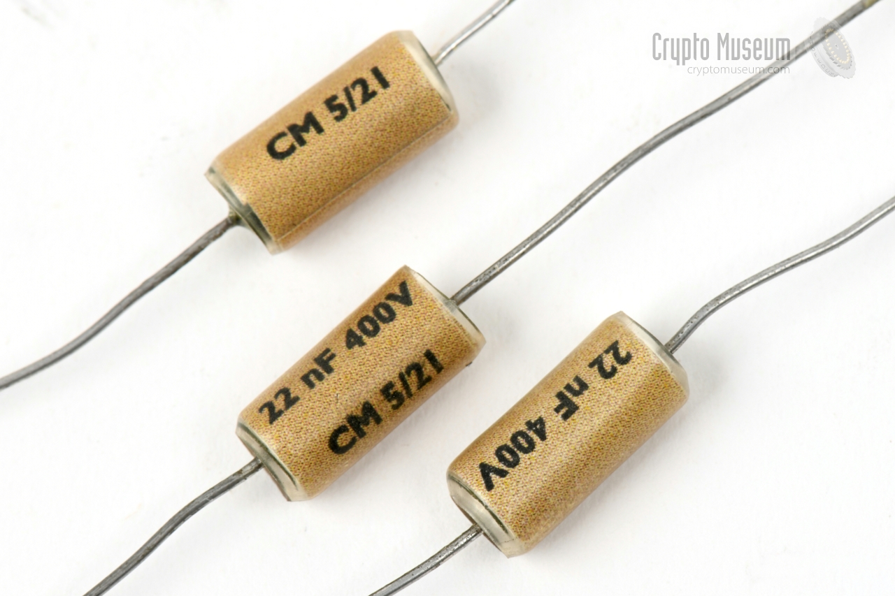
- 800 pF mica capacitor replaced
- All three 10 nF capacitors replaced
- Carbon microphone added
- 1 nF capacitor added between HT' and ground
|
Blindado Shielded Microphone (hot) Azul +AT Blue +HT voltage (75 to 90V DC) Blanco +BT White +LT voltage (1.4V DC) Verde común Green Ground (common)
|
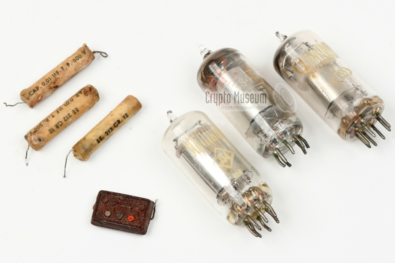
The 1S5 is a miniature tube consisting of a diode and a sharp-cutoff
pentode, developed for use as a combined detector and AF amplifier
in battery-powered portable devices. In the bug featured here,
it is used as a microphone pre-amplifier. Pinout as seen from the
bottom of the valve.
➤ 1S5 datasheet
|
The 3S4 is an audio pentode, also known as a beam tetrode, that was
developed in the late 1940s for battery-powered operation in portable radios.
It has two filaments which can be used in parallel or in series. In this
case they are connected in parallel, so that they can be driven by 1.4V DC.
The valve can be replaced by CV820 or DL92.
Pinout as seen from the bottom of the valve.
➤ 3S4 datasheet
|
Device Covert listening device Purpose Room overhearing Year 1953 (est.) Origin Spain (see below) User Spanish intelligence and/or police Discovered 1990, Le Perthus (France) Frequency 6.865 MHz Output 150 mW (est.) Antenna Wire (3 metres est.) Circuits Microphone amplifier (V1), AM modulator (V2) and Oscillator (V3) Valves 1S5 (V1), 3S4 (V2, V3) Power LT: 1.4V DC, HT: 75 to 90V DC Current LT: 230 mA, HT: 3 mA Dimensions 115 x 70 x 26 mm Weight 210 grams
|
|
Some of the components of the bug were manufactured in the UK,
such as the crystal (STC) and one of the valves (Brimar = STC).
The other valves are branded Sonitron (Spain). One of the
capacitors is branded Jeepson, Barcelona (Spain).
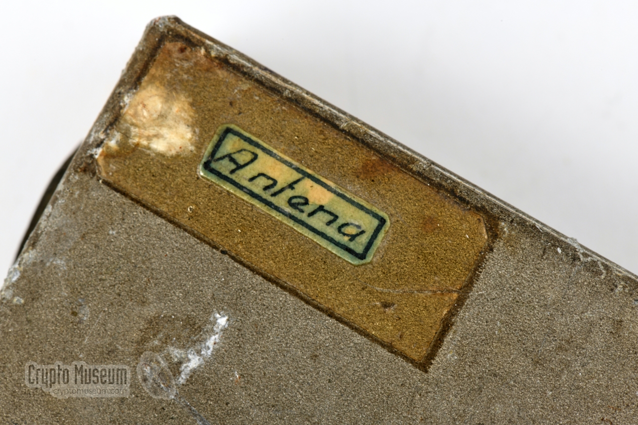
Furthermore, the text on the wiring layout label on top of the device
is in Spanish. Considering this, plus the fact that it has a limited range
and that it was found in a French customs office, it is very likely
that the bug is of Spanish origin.
|
Valve 1S5 Sonitron (Barcelona, Spain) 1 Valve 3S4 Brimar = STC (Kent, UK) Valve 3S4 Sonitron (Barcelona, Spain) 1 800 pF cap Jeepson, Barcelona (Spain) 10 nF caps Unknown brand - 2/1952 Crystal STC, Kent (UK) - 7/1952
|
|
As several of the parts have date markings of 1952, it is assumed that
the device was built not long thereafer, most likely between 1952 and
1954. This might have coincided with the building of the new customs
office at Le Perthus, which was opened in 1953.
|
-
Although this is not entirely certain, it is likely that SONITRON
was a brand name of radio and television manufacturer Radiodina in
Barcelona (Spain) at the time.
|
|
|
|
Any links shown in red are currently unavailable.
If you like the information on this website, why not make a donation?
© Crypto Museum. Created: Sunday 25 April 2021. Last changed: Wednesday, 05 November 2025 - 11:37 CET.
|
 |

|
|
|


![The French-Spanish border at Le Perthus in 1953, as seen from the French side [4]. Click to enlarge.](img/LePerthus_1953_large.jpg)


![The French customs office at Le Perthus around 1953 (the lower white building on the right) [4]](img/LePerthus_1953_thumb.jpg "image # LePerthus_1953_large.jpg")
![The French customs office at Le Perthus seen from the Spanish side [source unknown]](img/LePerthus_2_thumb.jpg "image # LePerthus_2_large.jpg")


![The French customs office at Le Perthus seen from the Spanish side [source unknown]](img/LePerthus_2_large.jpg)