|
|
|
|
|

|
|
RFT ← MSG-165
High speed morse and telex keyer
The MG-80(M) is an electronic morse keyer, also known as a
high-speed burst encoder, developed around 1982 by RFT in
Zwönitz in the former DDR (East-Germany), for use by the NVA – the
army of the DDR.
The device is suitable for the transmission of morse
and teleprinter signals.
It was part of the MGS-80 system, which consisted of an MG-80(M)
and a SV-81 power supply unit.
MGS-80 was the successor to the MGS-165, and was used until the
reunification of Germany.
|
The device is microprocessor controlled and is built to high quality standards.
The excellent keyboard supports both the Latin and the Cyrillic (Russian)
alphabet. All settings (e.g. transmission speed) are
controlled via the keyboard. The output level and tone pitch can be adjusted
with knobs on the vertical panel behind the keyboard.
The built-in memory allows 6 messages to be stored simultaneously
with a total capacity of 768 characters. 1 When sending directly from the
keyboard, a 16-character buffer prevents overruns and
allows typing at a higher speed.
|
|
|
Morse signals
can be transmitted at 30, 40, 50, 60, etc. up to 999
characters per minute, which is equivalent to 10...99 groups per minute.
Two buttons on the keyboard allow selection between Latin (LAT) and
Cyrillic/Russian (РУС) alphabets.
The morse signals are available on 4 different outputs: as an electronic
contact, a mechanical contact, as an audio tone and as a double-current signal.
A pair of headphones can be connected for monitoring the morse
in/out signals.
The MG-80 was used for transmitting messages at very high speed in order to
obtain a Low Probability of Intercept (LPI) and a Low Probability of Detection
(LPD) through Radio Direction Finding (RDF).
It can be seen as a security measure, as, unlike a manual key,
it does not reveal the characteristics of its operator.
It was also used as a training device for
future morse code
operators. When used for training purposes, the space
between characters and words could be extended.
Text can also be transmitted in ITA2 format,
at a speed of 45, 50, 100, 200 or 300 baud.
Text received in morse code is converted by the MG-80 into
ITA2 teleprinter code, which may then be printed on a connected
teleprinter. On the standard MG-80, the teleprinter signal is
available from two independent 45 mA double-current outputs.
On the MG-80M, one of the teleprinter outputs is swapped for a 20 mA
single-current teleprinter input. This allows the MG-80M to be used as a
transcoder from morse code to ITA2
(telex) and vice versa.
The MG-80W, was introduced around the time of the reunification of Germany (1990).
It is an enhanced version of the MG-80M, with improved hardware, expanded memory
and additional software features.
|
 |
-
The enhanced MG-80W version has a memory capacity of 3072 characters.
|
The image below shows a late version of the MG-80, manufactured in 1988,
with opened dust cover, seen from the front. The open dust cover holds
two metal clips that can be used as a copy holder. The horizontal part of
the front panel holds a full bi-lingual keyboard with German layout (QWERTZ).
The caps of the letter keys, each hold a Latin letter and its phonetic Cyrillic
equivalent.
Selection between Russian and Latin is done by means of the
РУС and LAT keys at either end.
The vertical part of the front panel consists of two parts: the left half
holds a series of LED indicators that show the PSU voltages,
the selected speed and the (teleprinter) functions. The right half holds
adjustments for output level, tone pitch and the volume of the headphones.
The image above shows the rear panel of the MG-80(M). At the far left
is a large 32-pin receptacle for connection of the
SV-81 power supply unit (PSU).
At the right are five 6-pin 10-series military connectors for the peripherals.
Four of these are identical female sockets, whilst the 2nd one – used
for connection of a receiver – is a male receptacle.
The pinouts are given below.
|
|
There are three basic versions of the MG-80:
|
- MG-80
The basic MG-80 is suitable for
transmission of morse code
and telegraphy signals (telex),
either in Latin or Cyrillic. It can be used for
high-speed (burst) transmissions,
but also for training purposes. Apart from morse code, messages can also
be transmitted in ITA2 teleprinter code.
Transmitted messages can be printed on a connected teleprinter.
- MG-80M
The MG-80M is an enhanced version of the MG80.
It is suitable for the reception of morse code and teleprinter messages.
One of the local teleprinter outputs is swapped
for a teleprinter input. This allows the device to be used as a transcoder
from morse code to
ITA2 teleprinter code and vice versa.
The MG-80M can be recognised by the
M-prefix on the serial number tag.
The MG-80 featured here, is of this type.
- MG-80W
The MG-80W is an enhanced version of the MG-80M. It is based on newer
hardware, with more memory and a backup battery to retain the last
selected mode of operation. It has an increased message size of 3072
characters (rather than 768), and an increased typing buffer of 64
characters (rather than 16). Furthermore, the firmware has been
enhanced with new features, some of which are for training purposes.
|
- Country
Apart from the bi-lingual version of the MG-80 featured here,
there were also versions for a single language, such as German.
- Keyboard
There were two basic keyboard layouts – a Latin one and a Russian one –
each of which had a number of variants.
➤ More
- Indicators
There are at least two different layouts of LED indicators on the
vertical part of the front panel. On some versions, the LEDs show
the number of characters per minute (ZpM), whilst on other versions
they show the number of groups per minute (GpM).
- Heater
With the first MG-80 devices, the heater was an optional feature.
It could be added later, and was fitted under the digital board,
at the bottom of the device. It allows the device to be used at sub-0°C
temperatures, and was a standard features of the later MG-80M.
- Firmware
To accomodate the different versions listed above, and the different
hardware in each of the models, it is likely that there were
quite a few (incompatible) releases of the firmware.
It is therefore unlikely that the firmware from one model/version will work
correctly in another model/version.
- Colour
The enclosure was available in (military) green or light blue.
|
|
 | Ein/Aus
On/off switch. Note that this switch is locked with a small spring-loaded lever to its right. This is done to prevent the device from being powered down accidentally. |
 | Latin
Selection of the Latin alphabet. Note that the desired alphabet must be selected before messages can be entered. |
 | Russian
Selection of the Russian (Cyrillic) alphabet. Note that the desired alphabet must be selected before messages can be entered. |
 | Figure shift
This key is only present on MG-80(M) devices with a Russian keyboard layout (SU-22). When in teleprinter mode, it generates the Figure-shift code, which may be required on certain teleprinter circuits. On these machines, the LAT-key is used as Letter-shift. |
 | Betriebsart
Mode of operation. After pressing the BA-key, one or more digits or letters must be entered to complete the command. During entry of the command, a LED at the front panel is illuminiated. Check out the manual for a full description of the various modes [C]. |
 | Gebetempo
Keyer speed (transmission speed) in ZpM or GpM. |
 | Irrung
Error. In morse code it sends a s eries of 8 dots (········), which is equivalent to the prosign 'ERROR '. Furthermore, it deletes the current letter group from memory. In telex mode it just sends a SPACE. |
 | In morse code this button sends the letter sequence 'AR' (·-·-·) without a gap between the letters. It is equivalent to the morse character '+' and the prosign 'END OF MESSAGE'. In telex mode it just sends a SPACE. This key is not present on all machines. |
 | In morse code this button sends the letter sequence 'AS' (·-···) without a gap between the letters. It is equivalent to the morse character '&' and to the prosign 'STANDBY' or 'WAIT'. In telex mode it just sends a SPACE. This key is not present on all machines. |
 | In morse code this button sends the letter sequence 'BK' (-···-·-) without a gap between the letters. It is equivalent to the prosigns 'BREAK' or 'BREAK IN'. It is used to 'hand over the key' without repeating callsigns, or to interrupt (break-in) a conversation between others. In telex mode it just sends a SPACE. This key is not present on all machines. |
 | In morse code this button sends the sequence (----), which represents the German letter combination 'CH'. It is one of the non-Latin additions to the morse code alphabet. In telex mode it sends the letter 'C', This key is not present on all machines. |
 | Release buffer memory |
 | Carriage return |
 | Line feed |
 | Enter |
|
|
The BA-key is used to select the mode of operation
(German: Betriebs-Art).
After pressing BA, the BA-LED on the indicator panel lights up.
You may now enter the desired mode (a number or a letter).
Some modes require additional parameters.
When the entry is complete, the BA-LED will go off again.
Full details can be found in the manual.
The following modes are available:
|
BA 1 Keyboard → transmit telex BA 2 Keyboard → transmit telex → memory BA 3 n Telex baud rate (1=100, 2=200, 3=300, 4=45, 5=50) BA 4 Keyboard → transmit morse BA 5 Keyboard → transmit morse and telex BA 6 Keyboard → transmit morse and telex → memory BA 7 Memory → Morse BA 8 Memory → Morse and Telex BA D Memory → Telex BA A 1 Random text → memory BA A 2 Random text → memory, transmit morse, keyboard → memory BA A 3 Random text → memory, transmit telex, keyboard → memory BA A 4 Random text → memory, transmit telex, receive morse → memory BA T Compare random text in memory BA W Select characters for random text BA M 1 Receive morse, transmit telex BA M 2 Receive and store morse, transmit telex BA F Receive and store telex, transmit morse GT n Fixed morse speed (n = 1 ... 7) GT 8 nnn Variable morse speed in ZpM (nnn) or GpM (nn)
|
The diagram below shows a typical setup with the standard MG-80. The device
is powered by an SV-80 (AC/DC) or SV-81 (AC) power supply unit
(PSU). The combination (MG-80 and SV-8x) is known as MGS-80. There are
connections for a transmitter, a pair of headphones, a morse key and one
or two ITA2 printers.
For use in cold environments, an optional heater can be installed.
Note that the printer connections are uni-directional. They can only be used
to print a message.
In 1986, the improved MG-80M was released, together with the improved SV-81
PSU. It has connections for the same peripherals as the MG-80,
but features an additional receiver circuit, which allows it to be used for
two-way communication. Furthermore, one of the printer outputs has been
given up in return for a bi-directional teleprinter connection.
This allows the device to be used as a transcoder — it can translate
morse code to ITA2 teleprinter data
and vice versa.
With the MG-80M, the heater – which was an option with the MG-80 – is built-in
as standard. It allows the device – in particular the digital circuits –
to be used at temperatures below 0°C, in which
case it takes approx. 15 minutes before it can be used reliably.
The heater is located at the bottom of the MG-80(M), directly below the
microprocessor board.
|
At the heart of the MGS-80 system, is the MG-80 morse keyer
shown in the image on the right. The device can be regarded as an
electronic terminal, similar to a teletype, on which messages can
be entered. The messages are buffered in the internal memory
and are transmitted at constant speed, either in
morse code or in the
ITA2 telegraphy alphabet (telex).
MG-80M is the enhanced version of the MG-80, which can be used as
a transcoder between morse code and teleprinter signals.
|
|
|
The MG-80 was supplied with a mains power supply unit (PSU)
that provided all necessary voltages.
The initial MG-80 (1982) came with an SV-80 PSU, but from
1986 onwards, the SV-81 shown in the image on the right was supplied.
It provides all positive and negative voltages for the microprocessor,
the audio circuits and the telex circuits, and is powered from the
110, 127 or 220V AC mains. It is connected to the MG-80(M) via a
single 32-wire cable.
|
|
|
|
At the rear is a connection for a pair of headphones,
that allows the outgoing signal to be monitored. The headset shown
in the image on the right was supplied with the kit. It was manufactured
by RFT Funktechnik Leipzig, and was modified for direct connection
to the MG-80(M).
|
|
|
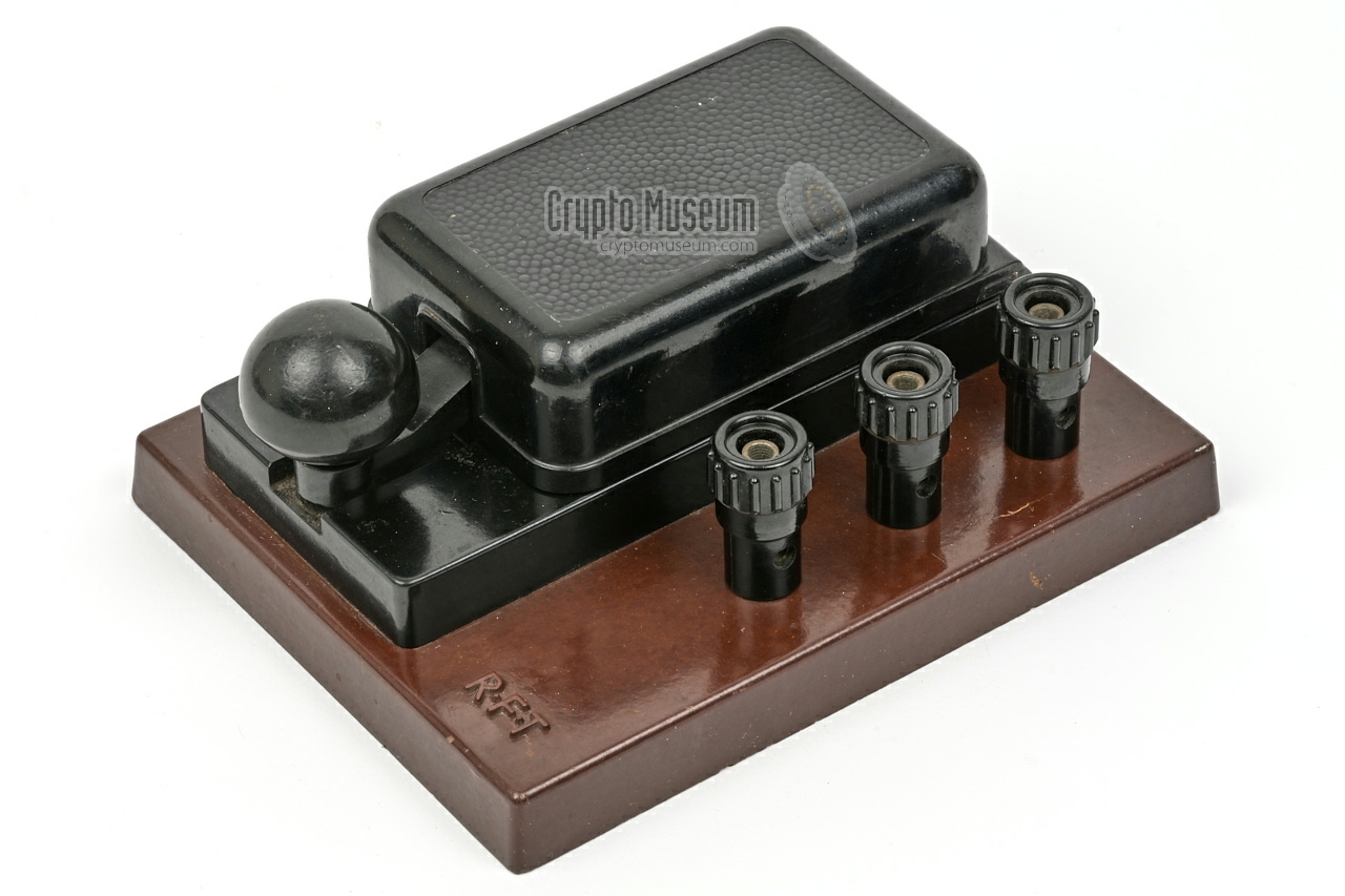
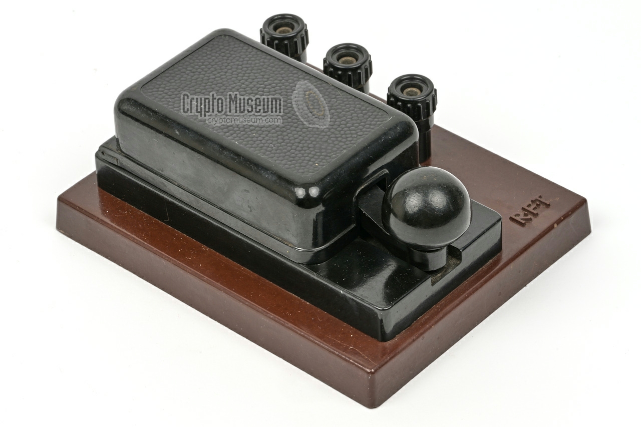
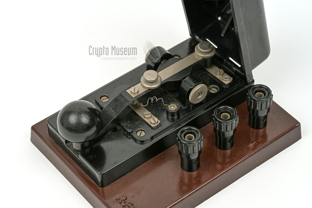
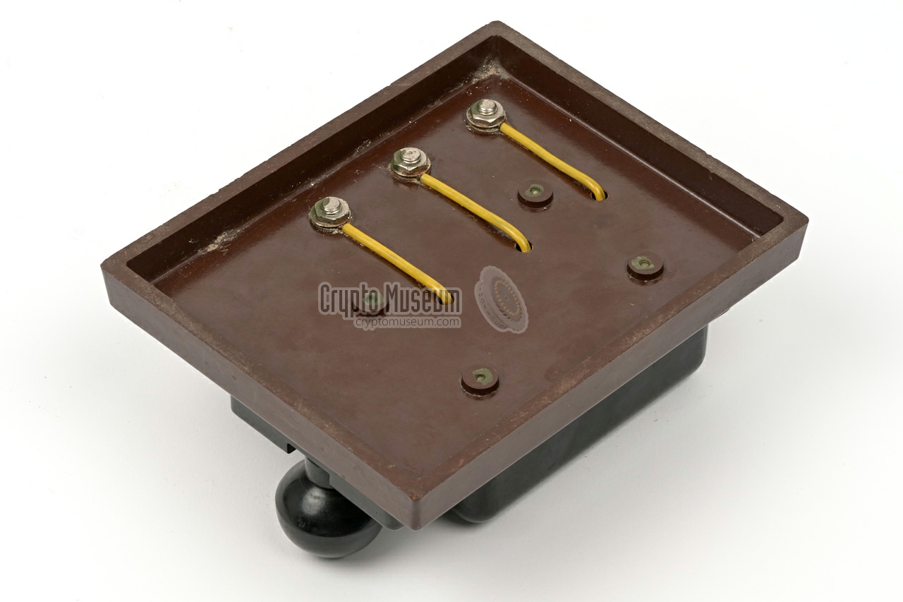
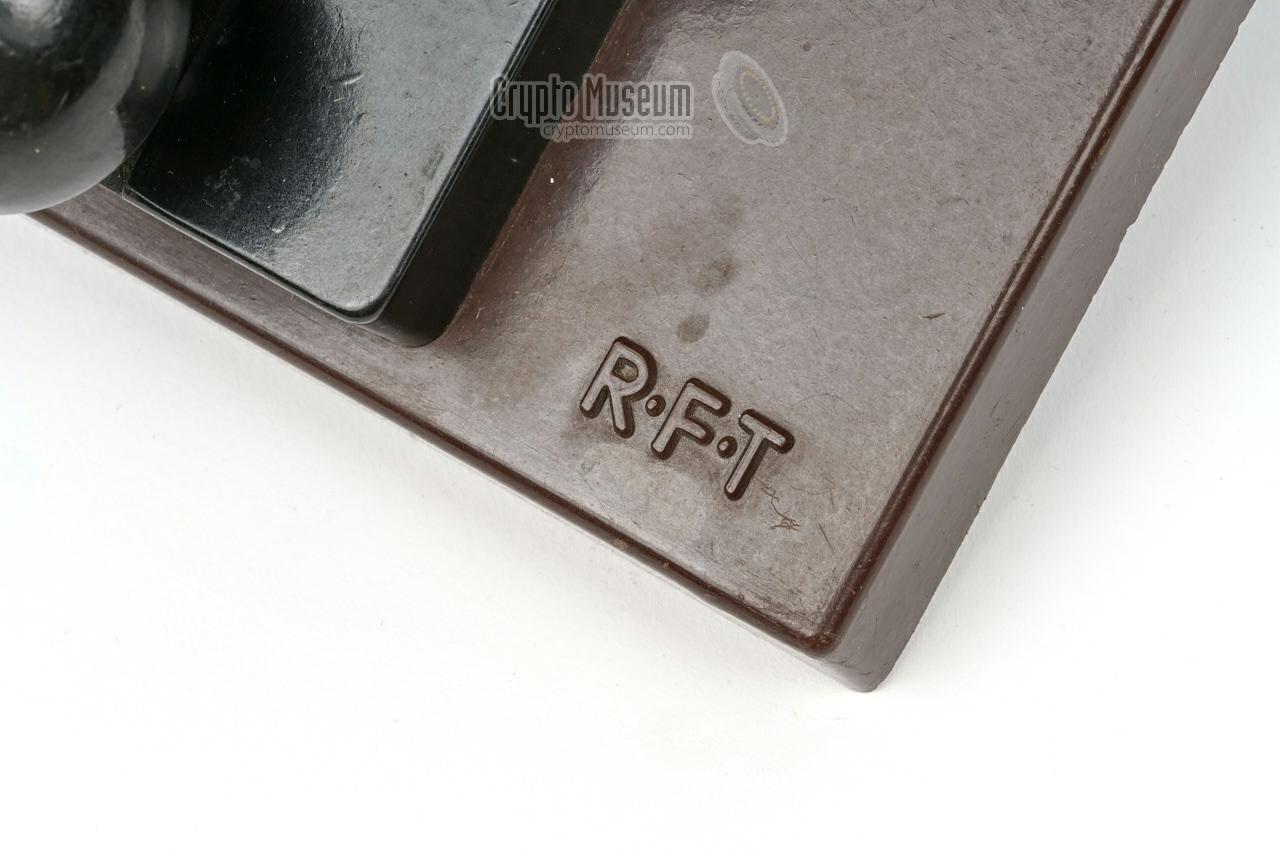
The MG-80 can be used with any type of morse key, of which the
East-German K40 was the most common one.
It was manufactured by RFT and is made of bakelite.
The image on the right shows an RFT K40 morse key, mounted on a
bakelite base plate. It has three contacts, that are available
on the three banana sockets to the right of the actual key.
|
|
|
The MG-80 was supplied with a full set of cables to connect
the device to the SV-81 PSU and to the peripherals, as shown
in the image on the right.
For the pinout of the connectors, please refer to the section
on Connections below.
➤ Connector wirings
|
|
|
|
Supplied with the kit was a brown envelope with a collection of
spare fuses, two recessed bolts and a mounting bracket. The latter
was used to fixate the device to a table, typically
when it was used in a mobile environment.
|
|
|
A small booklet was supplied with each MG-80, with full operating
instructions and pinouts of the various connectors. A separate
manual was supplied with the PSU.
At least three different versions of the operating instructions are
known — issued in 1982, 1984 and 1986 respectively — all of which
can be found in the Documentation section below.
➤ MG-80(M) manual (1986)
➤ SV-81 manual
➤ Other manuals
|
|
|
Each MG-80(M) came with a signed certificate to prove that it was
tested. The certificate holds the serial number (prefixed by 'M'
when it is an MG-80M), the manufacturing date and the signature of
the person responsible for the test.
The certificate also acted as a warranty card in case the device
exhibited a fault within the first year. The device listed on the
certificate shown in the image on the right, left the factory on
30 December 1988, less than a year before the Fall of the Berlin Wall
as part of Die Wende [6].
|
|
|
At the heart of the MG-80 is a Central Processing Unit,
or CPU (German: Zentrale RechenEinheit, or ZRE),
based on the Robotron Z-2521 board (part of the K-1520 computer system).
It features a UB-880 processor — an unlicenced microprocessor
based on the design of the Zilog Z80 [1].
The block diagram above roughly shows what is inside the MG-80.
At the heart is the K-2521 CPU board, based on a UB-880 (i.e. Z-80) processor.
The keyboard is on the left and is connected to PIO-B.
The LEDs and the data interface are both connected to PIO-A.
Some filtering is added to the I/O lines to prevent radio interference.
At the bottom right is the temperature control unit that drives the
(optional) heater. As the CPU can't reliably be operated at
low temperatures, the K-2521 board inside the MG-80
is kept in reset as long as the temperature is below 0°C.
|
|
The interior of the MG-80 can be accessed by removing two screws from
either side, after which the green cover can be removed.
This reveals the interior as shown in the image above.
Note that the rear panel is attached to the cover,
and that the wiring to the rear
panel connectors is rather short.
At the centre of the device is a vertical backplane
to which all other parts are connected.
|
The rear panel wiring can be detached from the device by removing the
rightmost connector (when seen from the front)
from the backplane. The adjacent connector holds the wiring to the front
panel. Three PCBs are accessible from the rear; from top to bottom:
the relay board,
the audio board and
the digital processor board.
The latter is a standard K1520 processor unit made by Robotron [8].
It is shown in the image on the right and is built around an East-German
8-bit UB880 microprocessor, which is fully compatible with the
popular western Zilog Z80 CPU.
|
|
|
|
The firmware is held in three EPROMs (the white parts in the image).
Furthermore, the processor board holds RAM and peripheral I/O adapters
(PIOs).
Note that this board is larger than the other two PCBs.
The wide connectors at the upper edge, mate with a second backplane
that is located under the keyboard PCB. It connects to the primary
backplane via a flatcable. For correct operation of the K1520
board, it is important that the temperature is within the specified
operational range of 0°C to +50°C. For this reason, the (optional)
heater is located directly below this board.
|
Note that there are quite a few layouts of the MG-80(M) keyboard.
If you have such a device, its keyboard might very well
be (marginally) different from the one featured here. As far as we know,
most keyboards are bi-lingual, although there were single-language
versions as well.
Basically, there are two versions of the keyboard layout: a German one (Latin)
and a Russian one. Each versions has a layout that is common to the
country/language, with the alternative language shown as a transliteration on the
same key. This makes it easier for native speakers to type a message in the
alternative language. In all cases, the Cyrillic characters are at the top,
and the Latin characters at the bottom. The keys LAT and
РУС are used to select between Latin and Russian
respectively. On the MG-80 and MG-80M, this setting is lost after a power cycle,
but on the MG-80W it is retained in its battery-backed RAM (also known as
non-volatile memory).
|
The Latin version of the MG-80(M) has a keyboard with a German typewriter
layout, also known as QWERTZ-order. This is similar (but not identical) to
the layout used in other countries with a Latin script. Below is the last known
layout, taken from a Czechoslovak training manual of 1991 [10].
In the former Soviet Union, this layout was known as SU-23. MG-80 and MG-80M
devices with this layout, always startup in Latin (LAT).
MG-80W devices remember the last chosen mode.
Note that there were also variants of this layout. Older versions
– typically the ones used in the former DDR (East-Germany) – have different
functions on the keys at the top right. Furthermore, the position of the Russian
letter 'Я' might be different. The alternative layouts are shown below.
|
The Russian version of the MG-80(M) has a keyboard with a typical
Russian typewriter layout. Below is the last known
layout, taken from a Czechoslovak training manual of 1991 [10].
In the former Soviet Union, this layout was known as SU-22. MG-80 and MG-80M
devices with this layout, always startup in Russian (РУС).
MG-80W devices remember the last chosen mode.
Note that in the Russian layout, the language selection keys (РУС and LAT)
are both at the right, whilst the key at the bottom left carries the (1...) symbol.
This allows the device to be used as a Russian teleprinter with the
MTK-2 alphabet — the Russian version of the ITA-2 alphabet.
|
The layout below was found on an MG-80 in the collection of
Michael Brandes in Germany [7] and Jozef Burda in Slovakia [9].
The differences with the SU-23 layout above are shown in red.
As this layout is also shown on the front page of all known manuals,
it is likely that this is the oldest one.
|
Below is the layout of the MG-80M in our collection, which was manufactured
in 1988 and used in the DDR (East-Germany). Differences with the
SU-23 layout above, are shown in red. It is believed that this was the last
layout used in East-Germany before the Fall of the Berlin Wall (1989) and the
subsequent reunification of Germany (1990). Note the different position of the
'Я' symbol.
|
The single-language German version of the keyboard shown in the diagram below,
was spotted on an early MG-80 unit, which is shown on the website of the
Raketen- und Waffentechnischer Dienst im Kdo. MB III [3].
It was photographed in the NVA Ausstellung Harnekop e.V. (Germany).
This version is similar to the SU-23a above, of which the Russian
characters have been removed.
|
|
Power for the MG-80M shown here, is provided by the separately provided
SV-81 power supply unit (PSU). It is connected to the MG-80 by means
of a thick short cable with a 32-pin male connector at one end and a female
one at the other end. Below is the pinout of the 32-pin connector, when
looking into the male receptacle at the
rear of the MG-80.
|
| A. | GND | Masse | Case ground |
| B. | 0V | 00 | Ground for +5V and +25V |
| C. | 0V | 00 | Ground for +5V and +25V |
| D. | 0V | 00 | Ground for +5V and +25V |
| E. | 0V | 0F | Ground for -5V and +12V |
| F. | -5V | 5N | Power -5V DC |
| G. | -5V | 5N | Power -5V DC |
| H. | - | - | Not connected |
| J. | - | - | Not connected |
| K. | +30V | 30P | Power +30V DC |
| L. | COM | 30M | Common for +30V and -30V |
| M. | -30V | 40N | Power -30V DC |
| N. | CTL5 | 5PF | Control voltage for +5V |
| P. | +5V | 5P | Power +5V DC |
| R. | +5V | 5P | Power +5V DC |
| S. | +5V | 5P | Power +5V DC |
| T. | +5V | 5P | Power +5V DC |
| U. | 0V | 00 | Ground for +5V and +25V |
| V. | 0V | 00 | Ground for +5V and +25V |
| W. | 0V | 00 | Ground for +5V and +25V |
| X. | 0V | 00 | Ground for +5V and +25V |
| Y. | +12V | 12P | Power +12V DC |
| Z. | +12V | 12P | Power +12V DC |
| a. | REM1 | E/A1 | Remote on/off (with 'h') |
| b. | +25V | UFs | Power +25V DC |
| c. | +5V | 5P | Power +5V DC |
| d. | +5V | 5P | Power +5V DC |
| e. | +5V | 5P | Power +5V DC |
| f. | 0V | 00 | Ground for +5V and +25V |
| g. | 0V | 00 | Ground for +5V and +25V |
| h. | REM2 | E/A2 | Remote on/off (with 'a') |
| j. | +5V | 5P | Power +5V DC |
|

|
|
The leftmost 6-pin socket at the rear of the MG-80
is used for connection to a transmitter.
A separate cable is provided for each of the
four possible configurations.
Each cable can be recognised by a coloured sleeve near the
plug. The red cable is used for the keyed output (TXC)
which is available as a galvanically isolated contact between pins A and D.
The green cable delivers
a galvanically isolated audio signal (TONE) on pins C and F.
The yellow cable provides a double-current teleprinter
signal (CUR) on pins B and E. The same pins (B and E) can be used to connect
an external relay, which is provided as a separate
cable with an in-line black box.
|
TXC Relay contact (with D) CUR Double current return (with E) TONE Isolated audio (with F) TXC Relay contact + (with A) CUR Double current (with B) TONE Isolated audio (with B)
|
|
Below is the circuit diagram of the relay cable — the cable with the
in-line black box. Inside the box is a reed relay with a protective
diode (D1) and a diode to avoid reverse current (D2). The latter also
reduces the voltage over the relay by 0.7V.
The reed relay is of the type RGK 30/1 - 1/104/01, manufactured by
Kombinat VEB Elektro-Apparate-Werke 'Friedrich Ebert'
in Berlin-Treptow [e].
It switches at 4V DC and can handle switching currents up to 1A.
➤ Datasheet
|
|
The MG-80 can also be used for the reception of tone signals.
The receiver must be connected to the second receptacle, which
is the only 6-pin male chassis part. Two isolated inputs are
available, each supporting a different input voltage. Pin D
is for signals with a maximun level of 2V, whilst pin F accepts
signals up to 30V. Both inputs use pin A as a signal return.
|
COM blue Signal return (for D and F) GND n.w. Case ground - - - IN1 green Audio in 1 (2V) against (A) - - - IN2 yellow Audio in 2 (30V against (A) - - -
|
|
|
At the rear of the MG-80, the 6-pin socket
marked with the symbol of a headset, is for connection of a pair of
headphones. Below is the pinout when looking into the socket.
|
- - GND Case ground (n.w.) SPK Speaker (return) - - - - SPK Speaker
|
|
- - GND Case ground (n.w.) KEY Morse key (return) - - - - KEY Morse key
|
|
OUT1 Output 1: 45 mA (with D) GND Case ground (n.w.) OUT2 Output 2: 45 mA (with F) OUT1 Output 1: 45 mA (with A) - - OUT2 Output 2: 45 mA (with C)
|
|
IN Input: 20 mA (with D) GND Case ground (n.w.) OUT Output: 45 mA (with F) IN Input: 20 mA (with A) - - OUT Output: 45 mA (with C)
|
|
Device Morse and telegraphy transmitter/receiver Purpose Burst transmissions, morse training Model MG-80 Part of MGS-80 Manufacturer RFT VEB Zwönitz Year 1982 Country DDR (East-Germany) Morse 30, 40, 50, 60, ... 999 characters per second (10-99 groups per minute) Telegraphy ITA2 standard at 45, 50, 100, 200, 300 baud Memory 768 characters Buffer 16 characters Initialisation < 3 sec (including self-test) Outputs see below Power SV-80, SV-81 Heater Option Temperature 0°C to +50°C Storage -40°C to +60°C Humidity 95% at +30°C Dimensions 395 × 380 × 175 mm Weight 9 kg Quantity 2000+ (est.)
|
|
|
MG-80M
differences with MG-80
|
|
|
Purpose Burst transmissions, transcoding, morse training Model MG-80M Year 1986 Power SV-81 Heater Standard Quantity 2500+ (est.)
|
|
|
MG-80W
differences with MG-80M
|
|
|
Model MG-80W Year 1990 (est.) Power SV-81 Memory 3072 characters Buffer 64 characters Battery Backup (for non-volatile memory) Quantity ?
|
Device Power supply unit (German: Stromversorgung) Purpose Power for MG-80(M) morse keyer, other devices Model SV-80 Part of MGS-80 Manufacturer RFT VEB Zwönitz Designator ELN 13713390 Year 1982 Country DDR (East-Germany) Successor SV-81 Input • 115/220 V AC (65 W)
• 10.8 — 30 V DC (38 W) Outputs ? Dimensions ? Weight ?
|
Device Power supply unit (German: Stromversorgung) Purpose Power for MG-80(M) morse keyer, other devices Model SV-81 Part of MGS-80 Manufacturer RFT VEB Zwönitz Designator ELN 13728290 Year 1986 Country DDR (East-Germany) Input 110/127/220 V AC (+10%/-15%), 47.5 — 63 Hz (65 W) Outputs see below Dimensions 160 × 180 × 240 mm (HWD) Weight 5.2 kg
|
+5 V DC 2.1 A -5 V DC 130 mA +12 V DC 120 mA +25 V DC 140 mA +30 V DC 30 mA -30 V DC 30 mA
|
Audio Tone signals ≥ 0.4V, < 2V Telex ≥ 6 V, < 30 V (20 mA) ← MG-80M only Manual Morse key
|
Electronic 60 V (100 mA) DC Mechanical Relay 110 V (100 mA) Tone -12dB to +10dB into 600Ω Telex Double-current ±30 V into 1.5kΩ (45 mA) 1 Headphones For monitoring transmitted and received signals
|
-
On the MG-80, two telex outputs are available.
|
- Morse keyer MG-80, MG-80M or MG-80W
- Power Supply Unit SV-80 or SV-81
- Headphones
- Morse key
- Cable, Power
- Cable, Contact (red)
- Cable, Audio (green)
- Cable, Double current (yellow)
- Cable, Relays
- Cable, Receiver
- Cable, Teleprinter (red) 1
- 2 recessed screws M5 × 25 mm
- Operating instructions
- Warranty card
|
|
|
| | S/N | Model | Year | Layout | Location | |
|
|
| • | 00309 | MG-80 | ? | SU-23a | Industriemuseum Chemnitz, Germany | |
|
|
| • | 0828 | MG-80 | ? | SU-23a | Jozef Burda, Slovakia | |
|
|
| • | 1023 | MG-80 | ? | SU-23a | Fernschreibamt-Hausneindorf, Germany | |
|
|
| • | 1311 | MG-80 | ? | SU-23b | Bw-Schmitti.de, Germany | |
|
|
| • | 1859 | MG-80 | ? | SU-23a | Udo Kell, Germany | |
|
|
| • | M0088 | MG-80M | ? | SU-23 | Dániel Molnár (HA5TBN), Hungary | |
|
|
| • | M0599 | MG-80M | ? | SU-23b | eBay (2026-06-05) | |
|
|
| • | M0707 | MG-80M | ? | SU-23 | Jozef Burda, Slovakia | |
|
|
| • | M0858 | MG-80M | 1987 | SU-23b | Private collector, Austria | |
|
|
| • | M1015 | MG-80M | ? | SU-23b | Manfred Bachmann (DK5FA), Germany | |
|
|
| • | M1317 | MG-80M | ? | SU-23b | Udo Labsch (DG5UDO), Germany | |
|
|
| • | M1506 | MG-80M | ? | ? | Klaus-Peter Jung (DH4PY), Germany | |
|
|
| • | M1614 | MG-80M | ? | SU-23b | Crypto Museum, Netherlands | |
|
|
| • | M1840 | MG-80M | 1988 | SU-23b | Crypto Museum, Netherlands | |
|
|
| • | M1972 | MG-80M | ? | ? | Klaus-Peter Jung (DH4PY), Germany | |
|
|
| • | M2090 | MG-80M | ? | SU-23b | Udo Labsch (DG5UDO), Germany | |
|
|
| • | M2371 | MG-80M | ? | SU-23b | YouTube (Richard's Lampensammlung, Germany) | |
|
|
| • | M2414 | MG-80M | ? | SU-23b | Fernschreibamt-Hausneindorf, Germany | |
|
|
|
K40 morse key MG-80 Service manual - SV-80 (old PSU) operating instructions
- SV-80 (old PSU) pinout
|
- MG-80 Bedienungsanleitung - Nutzung
MG-80 Operating Instructions (German).
RFT, VEB Messgerätewerk Zwönitz, 1982.
➤ Additional notes for training purposes (1983)
- MG-80 Bedienungsanleitung - Nutzung
MG-80 Operating Instructions (German).
RFT, VEB Messgerätewerk Zwönitz, 1984.
- MG-80(M) Bedienungsanleitung - Nutzung
MG-80 and MG-80M Operating Instructions (German).
RFT, VEB Messgerätewerk Zwönitz, 1986.
- MG-80 Werkprüfprotokoll mit Garantieurkunde
RFT, VEB Messgerätewerk Zwönitz. Warranty card (example).
December 1988, serial number M1840.
- Stromversorgung SV-81
RFT, VEB Messgerätewerk Zwönitz, 1984.
- MG-80 Operating Instructions (in Czech language)
Kv 176/87 III 27 28 186 1000 5153. RFT, 1987.
- Automatické Vysílače Telegrafních a Dálnopisných Znaků MG-80M a MG-80W
Czechoslovak Army MG-80M and MG-80W Training manual (in Czech language).
Spoj-53-18. Czechoslovak Army, Prague, 8 November 1990 (released in 1991).
- Morsegeber MG 80 - Reparaturanleitung
Repair manual for devices manufactured from 1983 onward (German).
III-6-15 4165-84 Kv 901-84. RFT, VEB Messgerätewerk Zwönitz. February 1984.
- ZRE K2521 (CPU) digital board circuit diagram
VEB Robotron ZFT, 15 April 1983.
|
- Wikipedia, U880
Retrieved December 2021.
- Robotron website, Morsegeber MG80
Accessed 14 January 2026.
- Raketen- und Waffentechnischer Dienst im Kdo. MB III, Morsegeber MG80
Accessed 15 January 2026.
- Udo Kell, Morsegeber MG 80
DDR Fernschreibtechnik (website). Accessed 15 January 2026.
- Büro- und Informationsgeräte, Morsegeber
Industriemuseum Chemnitz. Accessed 15 January 2026.
- Wikipedia, Peaceful Revolution
Accessed 15 January 2026.
- Michael Brandes, RFT Morsegeber - Typ MG80 und MG80M mit Zubehör...
Fernschreibamt Hausneindorf (website). Accessed 18 January 2026.
- Robotron website, K1520-Standard
Accessed 1 November 2009.
- Jozef Burda, SV81 + personal correspondence
sptech.sk (website). 27 November 2025.
- Automatické Vysílače Telegrafních a Dálnopisných Znaků MG-80M a MG-80W
Czechoslovak Army MG-80M and MG-80W Training manual (in Czech language).
Spoj-53-18. Czechoslovak Army, Prague, 8 November 1990 (released in 1991).
|
|
|
|
Any links shown in red are currently unavailable.
If you like the information on this website, why not make a donation?
© Crypto Museum. Created: Sunday 01 November 2009. Last changed: Friday, 03 July 2026 - 05:12 CET.
|
|

|
|
|
|
| |


