|
|
|
|
|

|
The electronic device is partly mechanical. It has a fixed internal
ferro-magnetic audio tape that can hold just over 10 minutes of data
in morse code,
which is entered by means of a morse key that is
connected to one of the audio sockets.
Once a morse coded message has been recorded at regular speed, it can
be played back through a connected transceiver and 10 times
the speed. This minimises the time that the transmitter is on air
and, hence, the chance of
interception and detection.
As a result it will be more difficult to locate the station by means of
direction finding.
|
|
|
A signal that is sent at high speed, is known as a burst transmission.
Unlike many other burst encoders,
the MA-4010 can not only be used for
initiating burst transmissions, but also for receiving them. When
recording a message, the clock indicator
at the centre of the front panel shows how much tape is used
(in minutes). The device's status is shown by three red LEDs.
It is currently unknown who the primary user of the MA-4010 was, but
it is likely that they were used by special military services, such as
the Special Forces (SF). The model number tag
suggests that there were several variants of the device,
which might explain the inconsistency between the service manual [A]
and the actual AUDIO sockets of the
MA-4010/8 featured on this page.
It is one of the last electromechanical burst encoders,
before the arrival of fully electronic ones.
|
All controls and connections of the MA-4010 are located at the front panel,
with the exception of the power terminals, which are at the rear.
The unit is suitable for connection to a short wave (SW) radio, and should be
inserted between the handset and the transceiver. It requires a
morse key to be connected to the second audio socket. Ensure the tape is
fully wound back to the start.
The required mode of operation is selected with the 9-position knob
at the bottom right. In the centre position, the device is turned OFF.
The 4 positions on the left are used for entering and transmitting a message.
Likewise, the 4 positions on the right are used for receiving a message.
When recording a message, the clock indicator at the center shows the
tape progress. The current status of the device is reflected in three
LEDs, REC,
AUX
and RUN, just below the clock indicator.
|
|
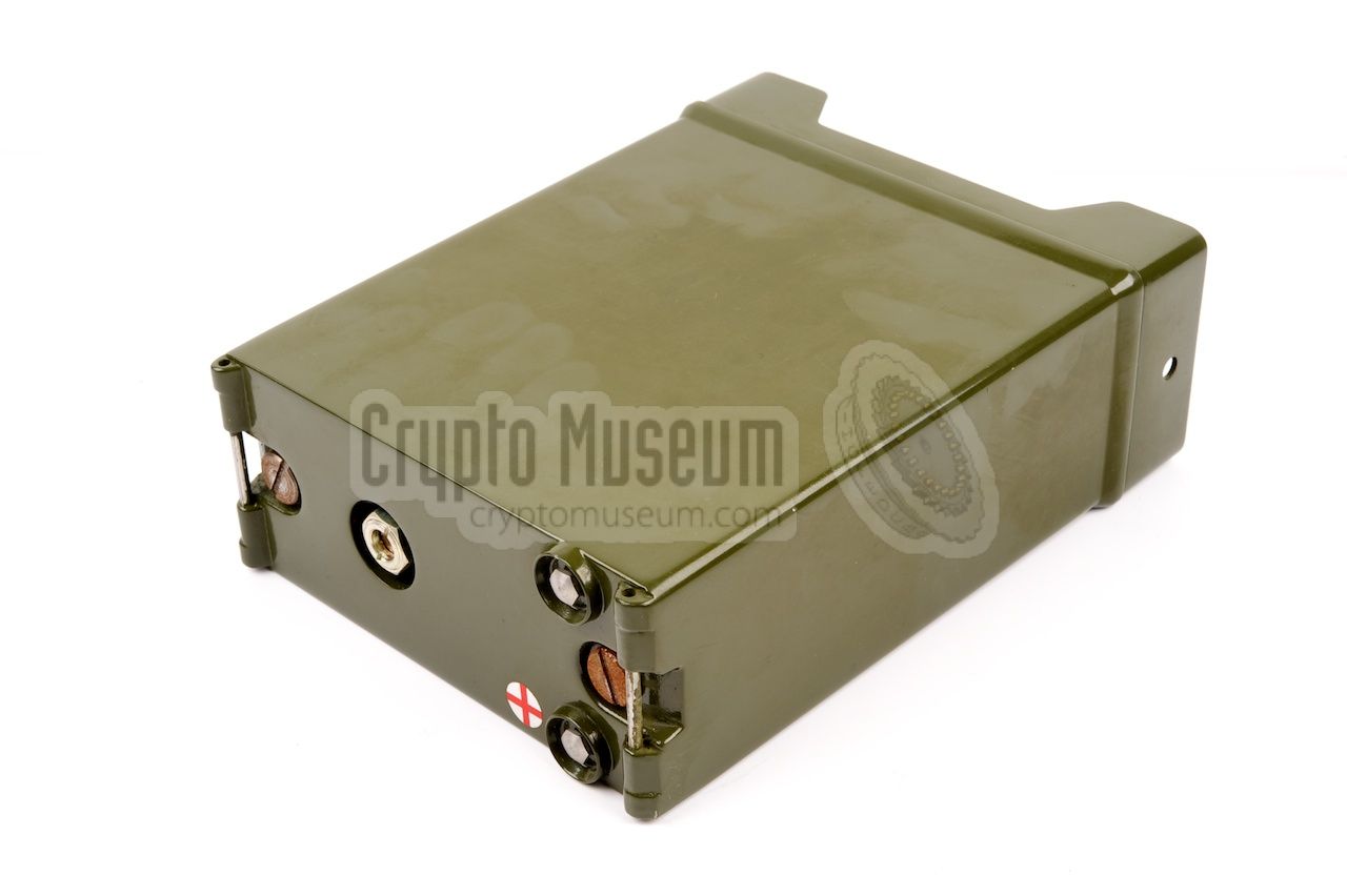
The MA-4010 is housed in a metal enclosure that is nearly identical to that
of the Racal
MA-4204 time domain voice scrambler,
that was developed around the same time. It consists of a metal frame that holds
all mechanical and electronic circuits, and that is attached to the front panel.
|
The device is enclosed by a metal case shell, that can be removed by loosening
the two large bolts at the rear and sliding it off.
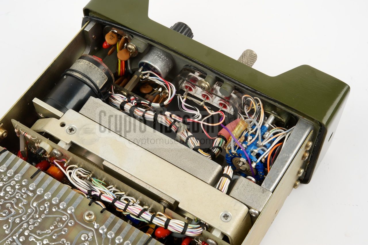
The front half
of the interior is occupied by the mechanics of the tape recorder
that also holds the ferro-magnetic tape.
The rear half
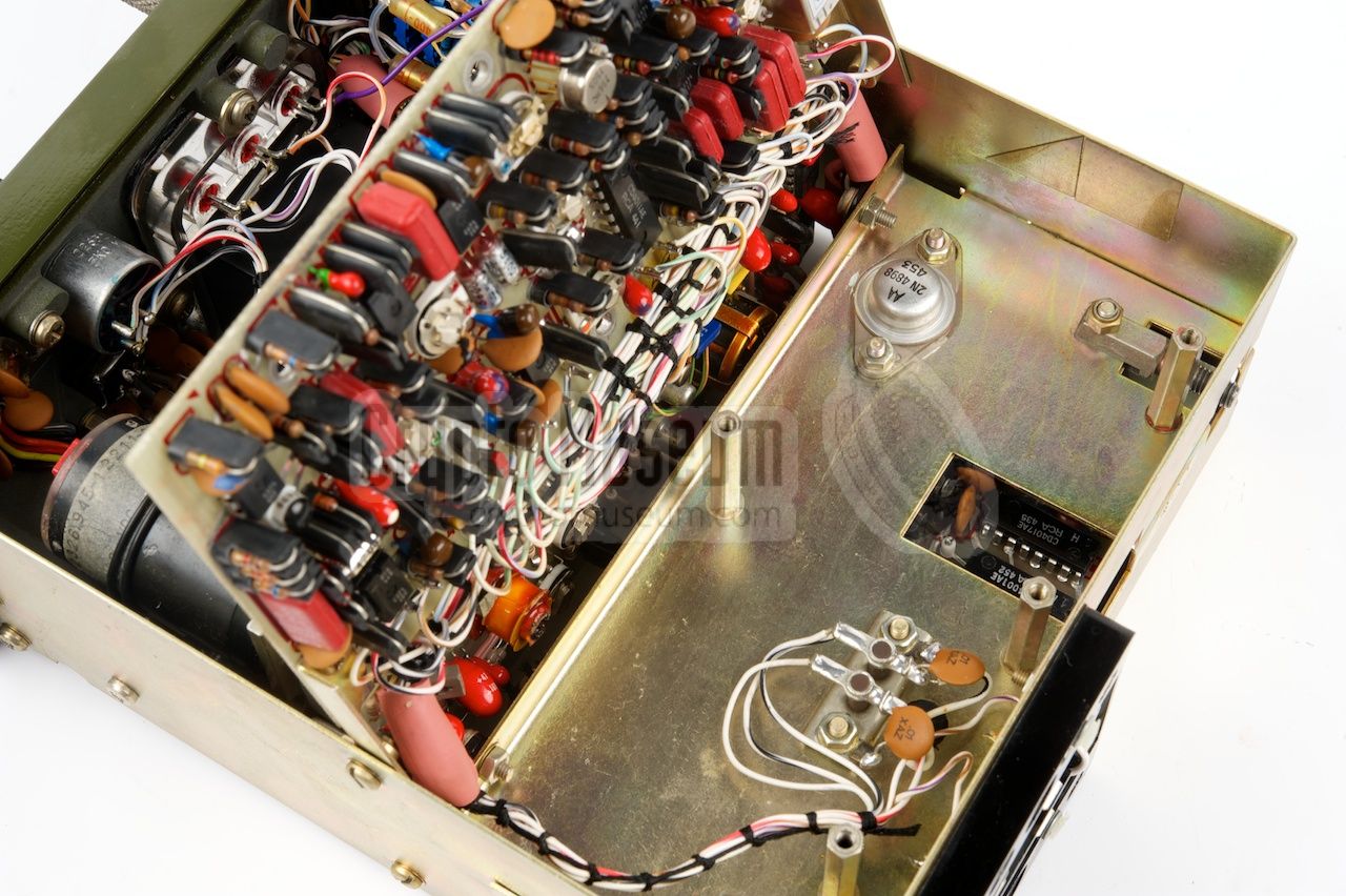
of the frame contains the electronic circuits, which are divided
over three densely populated printed circuit boards (PCBs),
two of which are hinged and can be
tilted outwards as demonstrated in the diagram above this section.
This makes the device very service-friendly.
The boards are interconnected by bundled wiring.
|
|
|
|
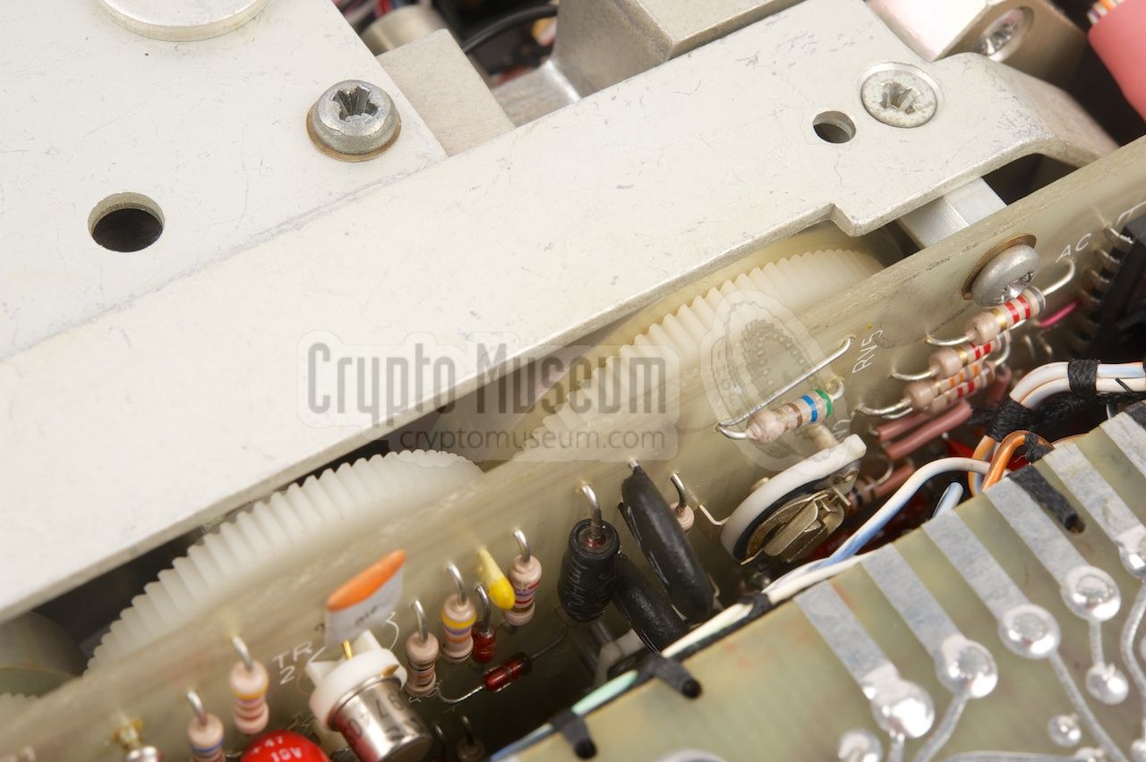
The mechanical section is more difficult to access. It consists of
several high-precision machined parts, that are driven by a
small electromotor
via a series of nylon cogwheels.
The device can be powered by an external battery that is attached
at the rear side. Alternatively, it can be powered directly from the
transceiver, via the 6-pin
Clansman-standard
TCVR socket
on the front panel.
|
|
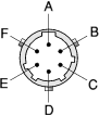
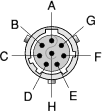
All connections of the MA-4010 are at the front panel. In total,
there are three audio sockets — one of which connects the unit to
the transceiver — and a ground terminal. The pinout of the three
sockets is given below. Note that the pinout of the two 6-pin audio
connectors is different from the 8-pin audio sockets of the
MA-4010/8
that is featured on this page.
|
- Mic (input)
- Battery charging (+)
- PTT (input, switched to ground)
- Ground (battery charging –)
- Key
- Speaker (output)
|
|
- Mic (input)
- Power supply to ancillary (+)
- PTT (input, switched to ground)
- Ground (ancillary –)
- Key
- Speaker (output)
|
|
- High speed key output (or microphone output)
- Auxiliary power input (+)
- PTT (output)
- Ground
- Key (output) 1
- Speaker (output)
|
|
-
Except in KEY, CHECK, REPLAY or during high-speed transmission.
|
|
The MA-4010/8 version of the device, which is featured on this page,
has two 8-pin female audio sockets, rather than the 6-pin Clansman type
specified in the manual (and in the tables above). The wiring of these
sockets is currently unknown.
|
|
At present we have no further information about the Racal MA-4010.
If you have any additional information, such as a user manual or
the pinout of the 8-pin audio sockets,
please contact us.
|
- MA-4010 circuit diagrams and parts list 1
Racal Datacom Ltd. Date unknown.
|
|
|
|
Any links shown in red are currently unavailable.
If you like the information on this website, why not make a donation?
© Crypto Museum. Created: Friday 30 June 2017. Last changed: Saturday, 01 July 2017 - 08:35 CET.
|
 |

|
|
|