|
|
|
|
|

|
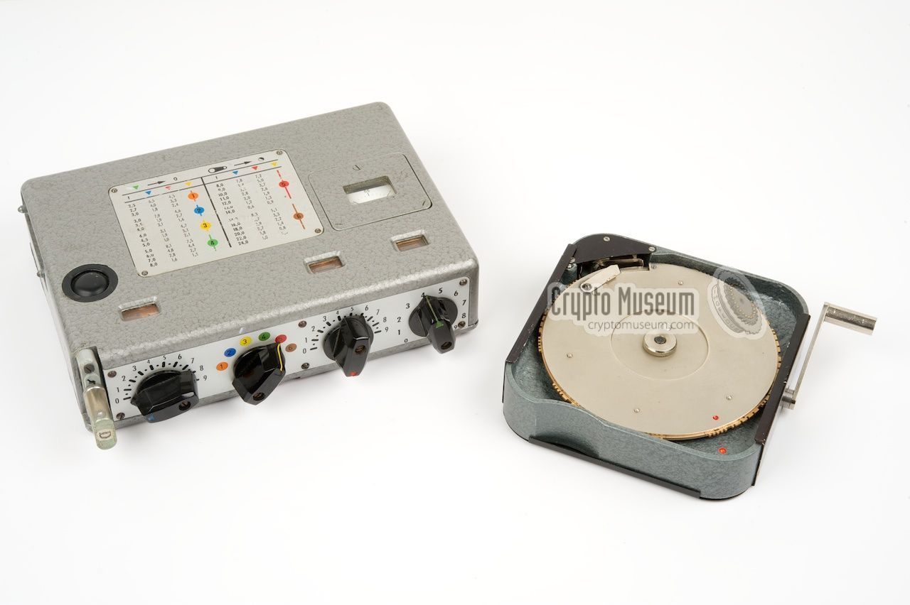
Electromechanical burst encoder
The KSG, or Kurzsignalgeber (Burst Transmitter), was an electromechanical
morse burst encoder,
that was developed by the German Intelligence Service,
the Bundesnachrichtendienst (BND),
and introduced around 1957.
It was intended to be used in combination with the
FS-8 transmitter,
a predecessor of the FS-7,
but could also be used with other spy radio sets, such as the
SP-15
[2].
|
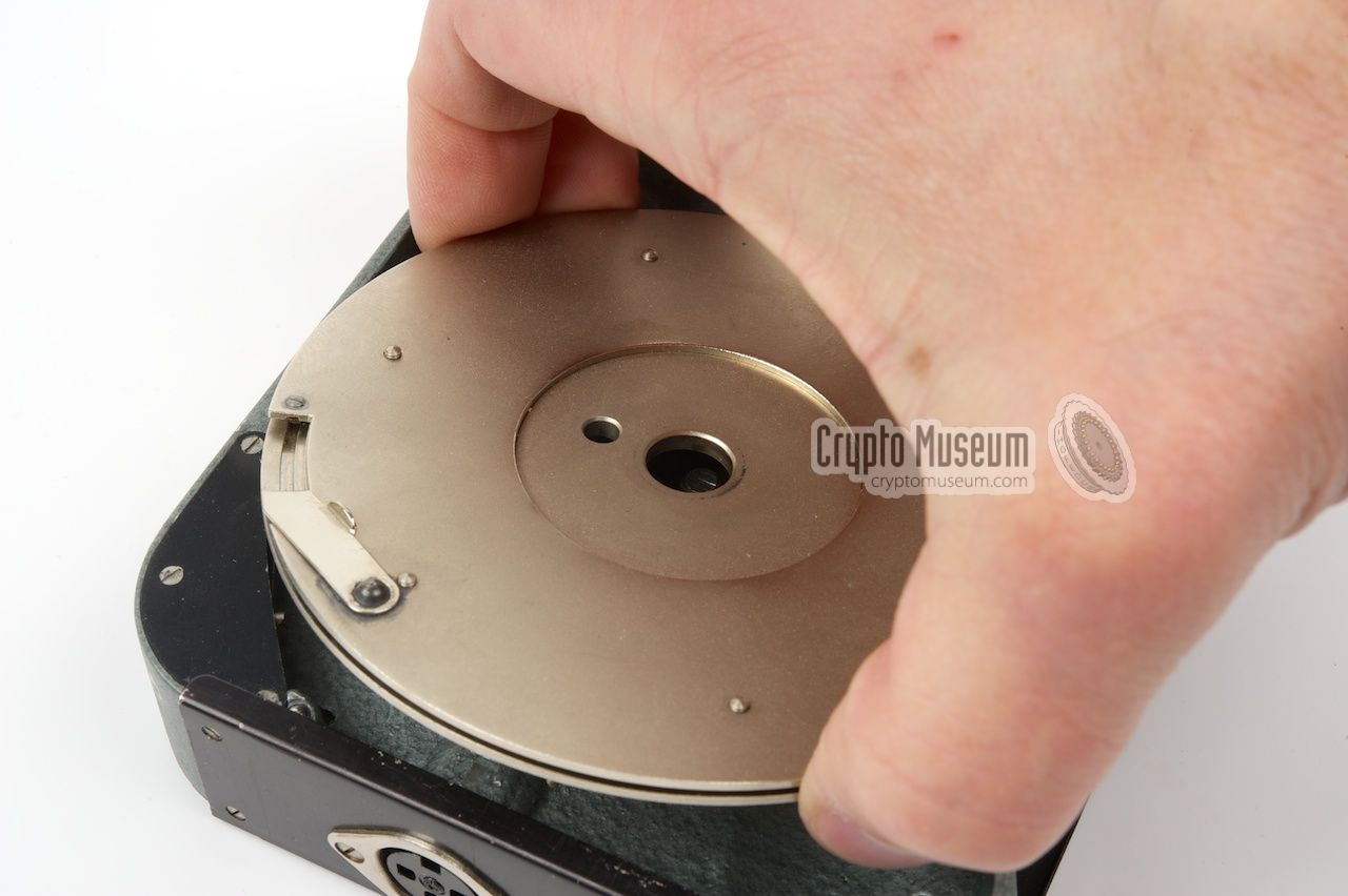
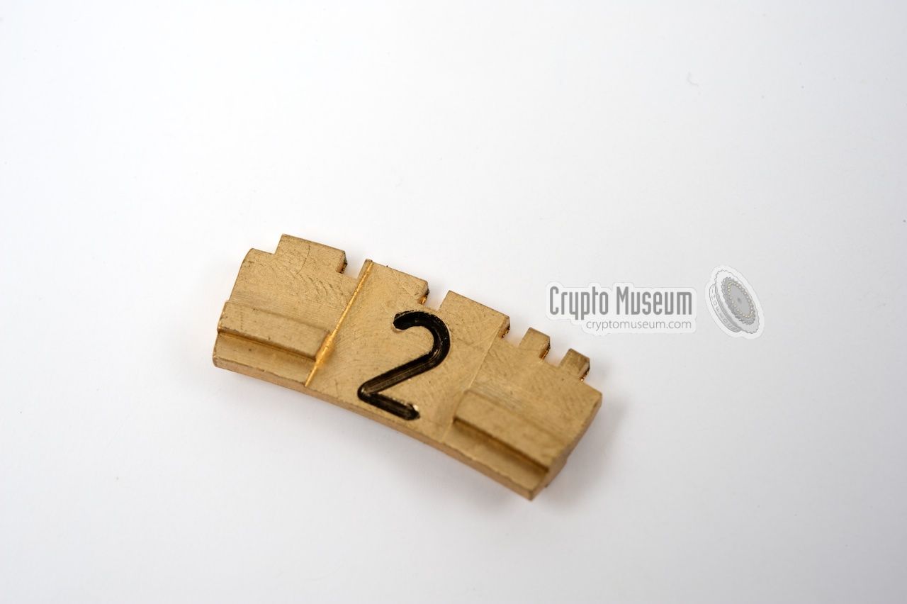
The notches are actually the mechanical representation of the engraved
number in morse code.
This is also the reason why most insert can be used
for two different numbers. For example: the
morse 2 ··--- can be used
as the 8
---·· simply by reversing it. The tweezers are used to
pick the required numbers
from the box and insert them
into the metal disc
at the top side of the device.
|
When coding a message, the plain text is first translated to numbers using some
kind of conversion scheme. The numbers are then added to the numbers from
a so-called One-Time Pad,
a list of truely random numbers of which only
two copies exist. When properly used, the
One-Time Pad code is unbreakable.
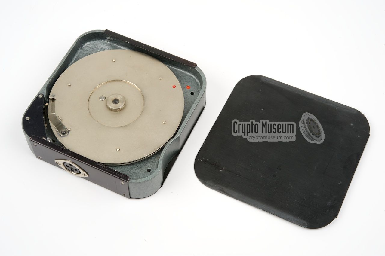
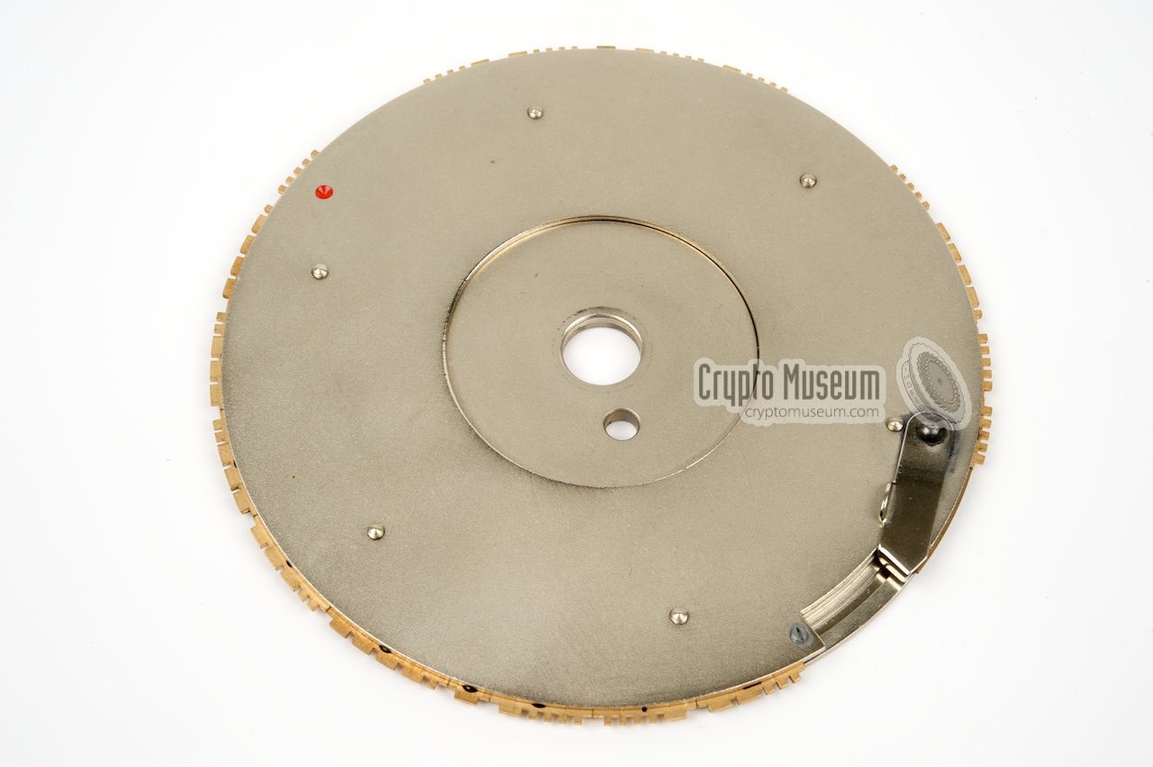
Once the message is encrypted, the
metal disc is removed from the top side
of the KSG and the numbers of which the cipher text consist are
inserted into the disc in reverse order.
Short messages are padded with spaces or garbage.
|
|
|
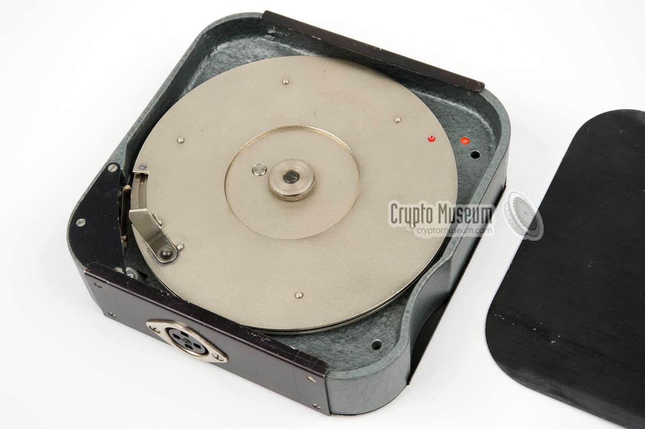
Once the KSG is connected to the transmitter and the transmitter is tuned,
the transmitter should be turned on and the operator rotates the
crank of the KSG with a constant speed between 1 and 2 revolutions per
second until the red dots are aligned again. This takes about 7¼ turns.
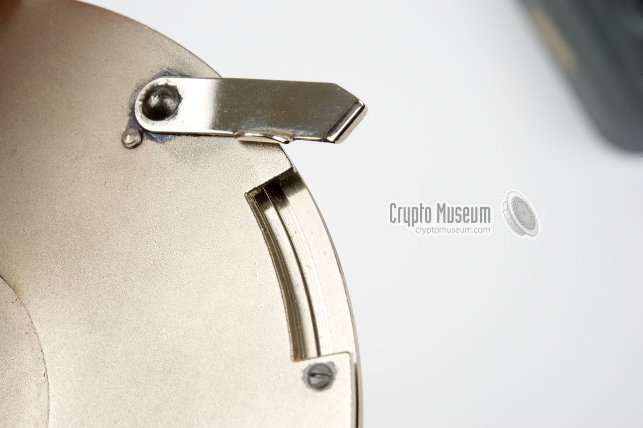
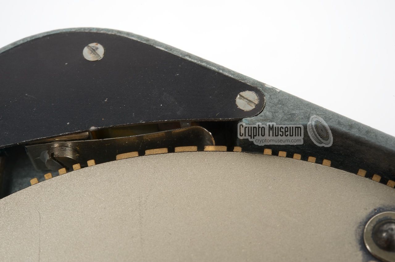
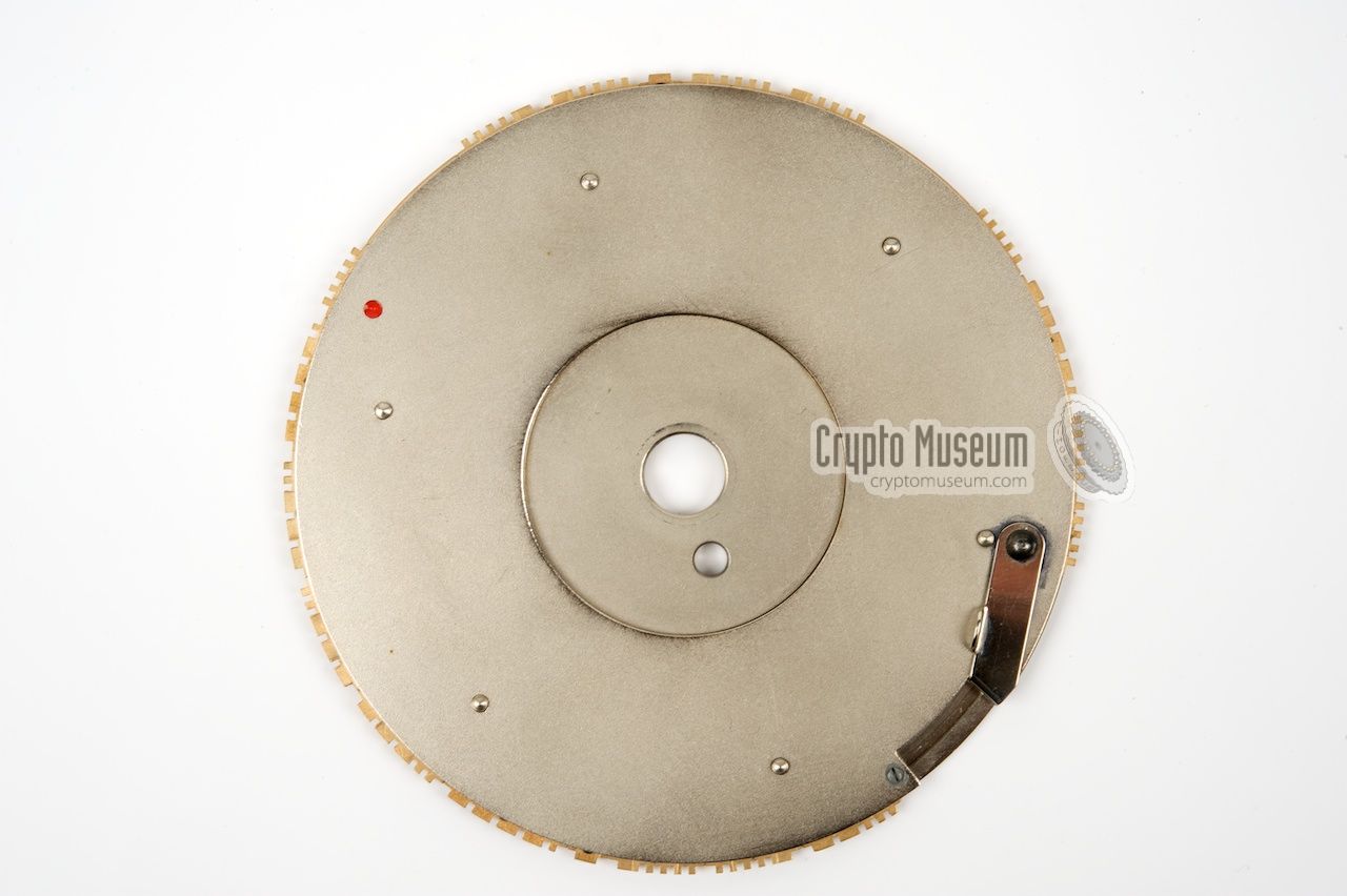
When rotating the metal disc, a small switch,
mounted in one corner of the device,
senses the notches
of the inserts that represent the morse dots and dashes.
Whenever it meets a notch, the switch is closed and the transmitter
(CW) is turned on. In between the notches it is off.
|
|
|
This way, the entire message is transmitted in morse code in less than 8
seconds. The KSG was used by the BND for Stay-Behind operations during the
Cold War (sometimes referred to as 'Gladio'). It was initially used in
combination with the matching KSG Transmitter.
It was also used with the SP-15 spy radio set
that was introduced in the early 1960s, before it was replaced by
other models, such as the RT-3,
the GRA-71,
the Speicher
and eventually the digital MMP.
|
|
|
FS-8 Transmitter
KSG-Sender
|
|
|
Wanted item
The KSG burst encoder was initially designed for use in combination with a
small clandestine 7.5W transmitter, the so-called FS-8 or
KSG-Sender (KSG transmitter),
which was also developed by the
Bundesnachrichtendienst (BND)
and built by the German manufacturer Hirschmann [1].
The image above shows an example of an original FS-8 from the
former collection of Detlev Vreisleben in Koln [1]. The cable at
the left is for connection to the KSG burst encoder. The cable at
the right goes directly to the AC mains (110 or 220V). At the
right side are two banana-type sockets for the antenna and the
counterpoise. Crypto Museum are currently looking for a
FS-8.
If you know of one that might be available, please contact us.
➤ More about the FS-8
|
|
Although the KSG was developed for the accompanying FS-8 transmitter, it was
also used with the later SP-15 spy radio set
before it was replaced by other models. Evidence for this can be found
in several documents and publications, such as the 1969 book
Nicht länger Geheim [2].
|
This book was was published in East-Germany (DDR) during the Cold War and
exposes Western European (BND) and American (CIA) espionage activities
against the Warsaw Pact countries.
The book was replublished in 1975 with even more espionage cases.
The image on the right shows a page of the 1975 edition, on which
a captured SP15 spy radio set
is shown. According to the caption it was found an a BND agent.
At the top is the FS-7 transmitter
with its mains power supply. At the right is the KSG encoder.
|
|
|
In front of the transmitter is a set of crystals and a roll-up
antenna. The paperwork at the front consist of operating instructions
frequency tables and a map. At the far left is a metal container
with a roll of One-Time Pad cipher material
which is, of course, compromised in this case.
|
The electrical circuit diagram of the KSG is very simply. In fact it is
nothing more than a small switch (that senses the the gaps and notches
on the outer rim of the disc) with two 100 ohm series resistors to reduce
the current, and a capacitor that acts as a spark killer. Like this:
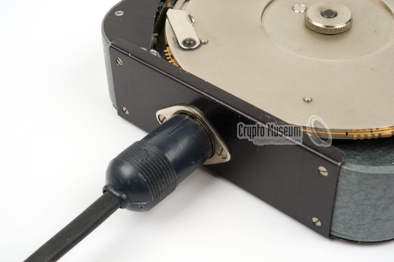
Connecting the KSG to the KSG-Sender
is straightforward, as the latter
already has a fixed cable with a suitable 3-pin DIN plug for direct
connection to the KSG. When connecting the KSG to the later
FS-7 transmitter,
a conversion cable to the 5-pin 270° socket of the FS-7 is needed:
|
- Bundesnachrichtendienst (BND), KSG Operating instructions (German)
Date unknown, probably around 1957. 6 pages diary format. 1
|
- Detlev Vreisleben, Images, documentation and backgrounds of KSG and KSG-Sender
Personal correspondence. December 2014.
- Albrecht Charsius & Julius Mader, Nicht länger Geheim
Berlin, 1969. 2nd edition, 1975.
|
-
Kindly supplied by Detlev Vreisleben [1].
|
|
|
|
Any links shown in red are currently unavailable.
If you like the information on this website, why not make a donation?
© Crypto Museum. Created: Tuesday 02 December 2014. Last changed: Friday, 30 June 2017 - 07:28 CET.
|
 |

|
|
|


![FS-8 (KSG-Sender) - wanted opject, copyright Detlev Vreisleben [1]](../../spy/ksg/img/302040/000/wide.jpg)