|
|
|
|
|

|
|
Cold War USA ← RS-1
Spy radio set
The RS-6 was a spy radio set,
developed in 1951 in the USA
by the US Central Intelligence Agency (CIA)
and built by Motorola,
especially for overseas agent communication.
The design is clearly based on the earlier - bulky - RS-1.
The RS-6 is in fact much smaller and weighs far less than its predecessor,
mainly due to the use of subminiature valves and lighter metal enclosures.
|
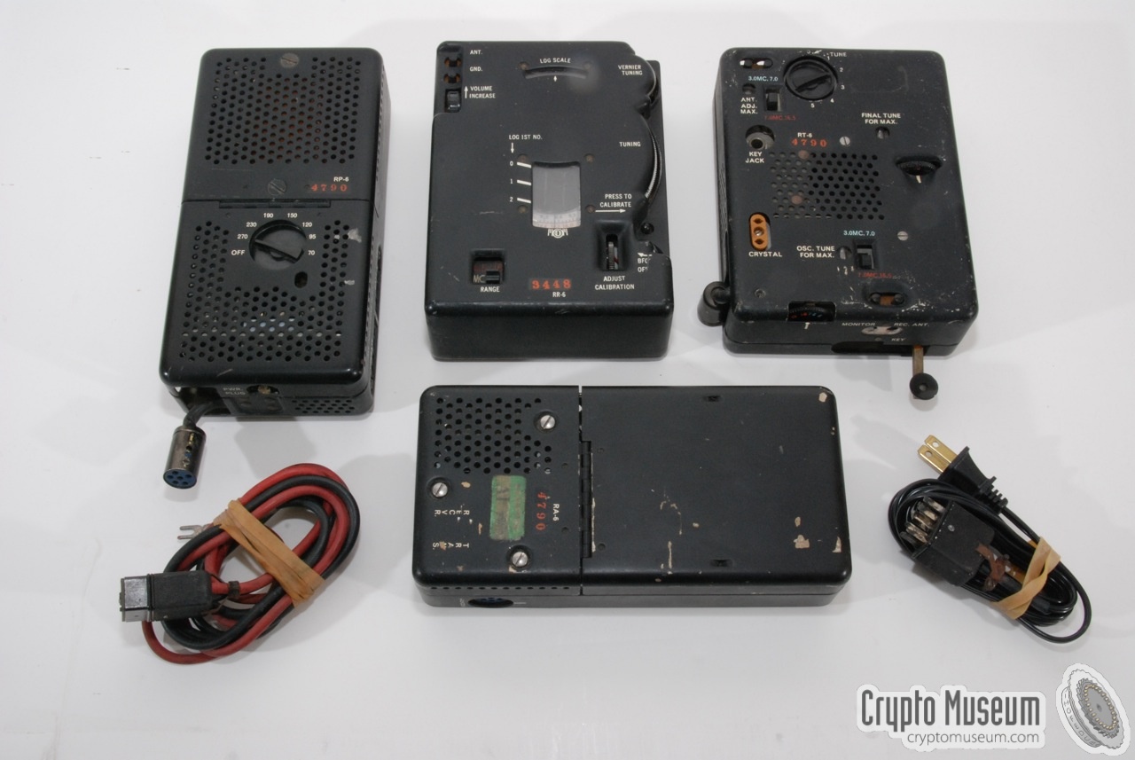
A complete RS-6 set consists of 4 units as shown in the picture on the right.
On the left is the power supply unit (RP-6) that is suitable for a range of
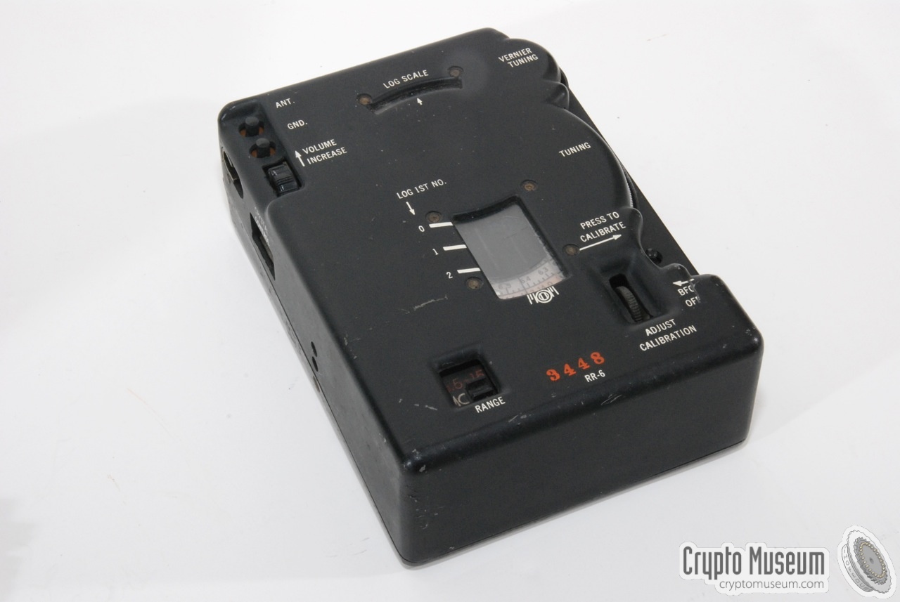
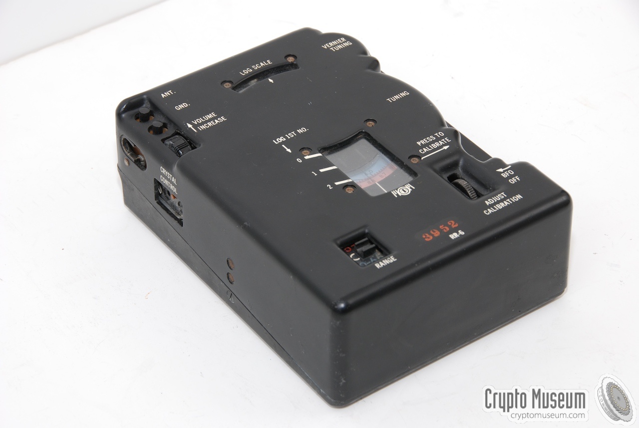
mains voltages. At the centre is the receiver (RR-6) that has a rather big
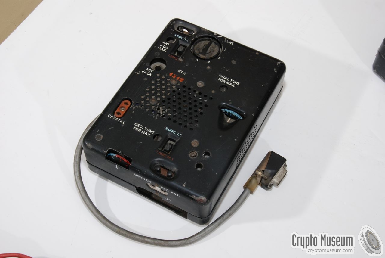
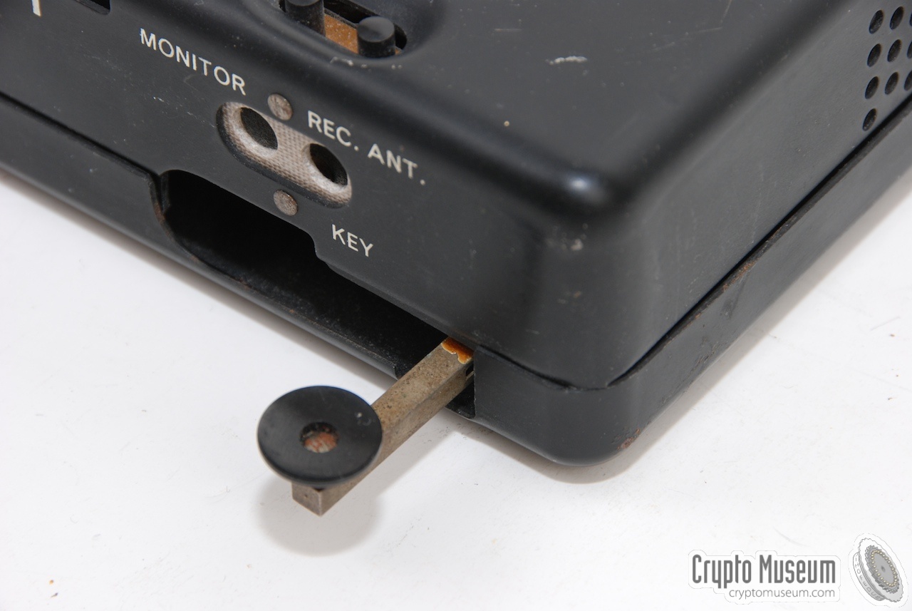
dial with 2 frequency ranges. The unit at the right is the transmitter (RT-6)
which has a rather clever retractable morse key at the front right.
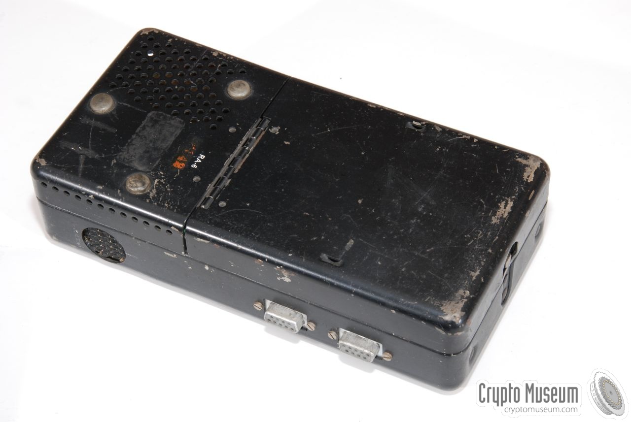
The unit that lies in front of the other three, is the power Filter Accessory
Unit (RA-6) half of which is used as a storage compartment for the various
cables that originate from this unit.
|
|
|
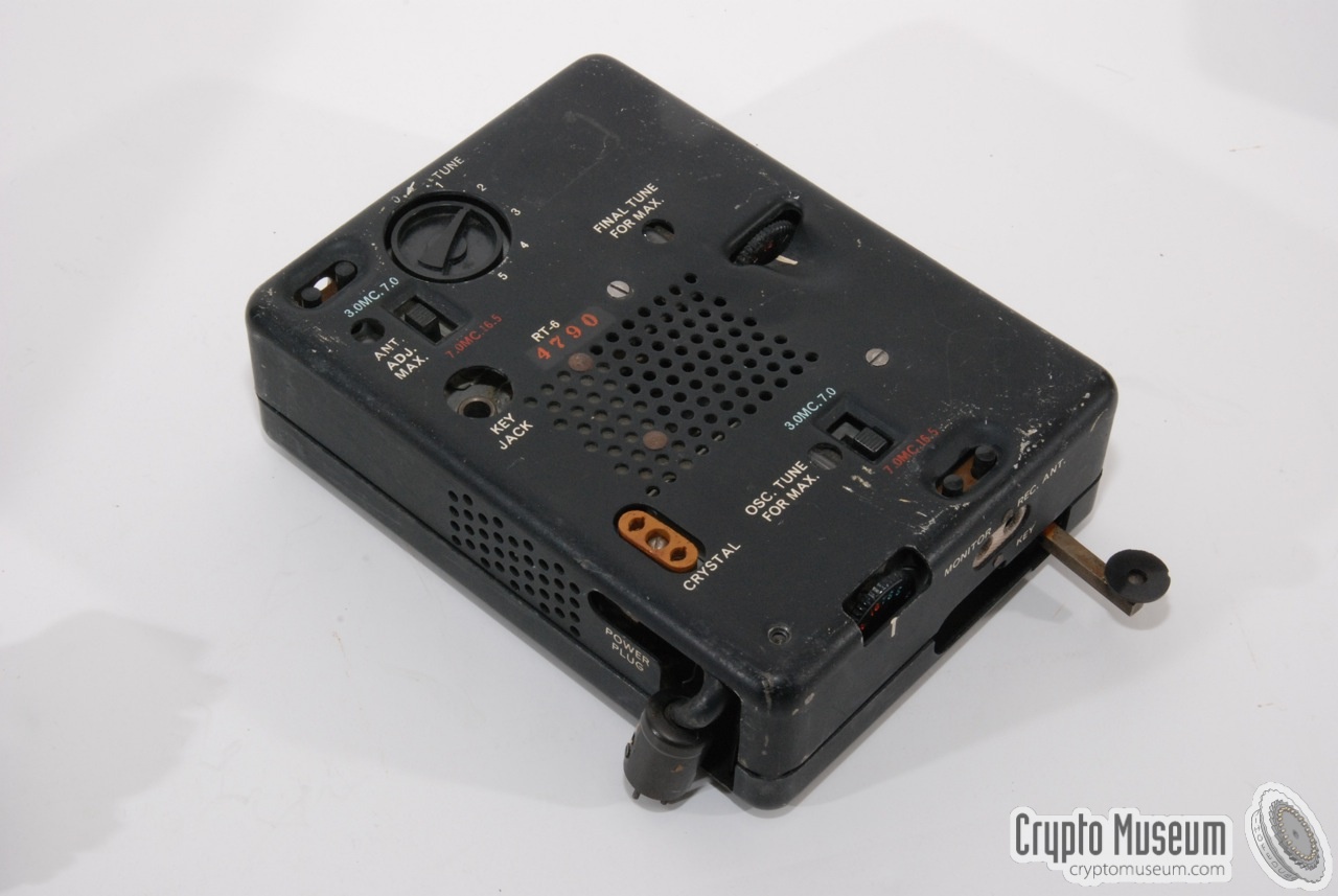
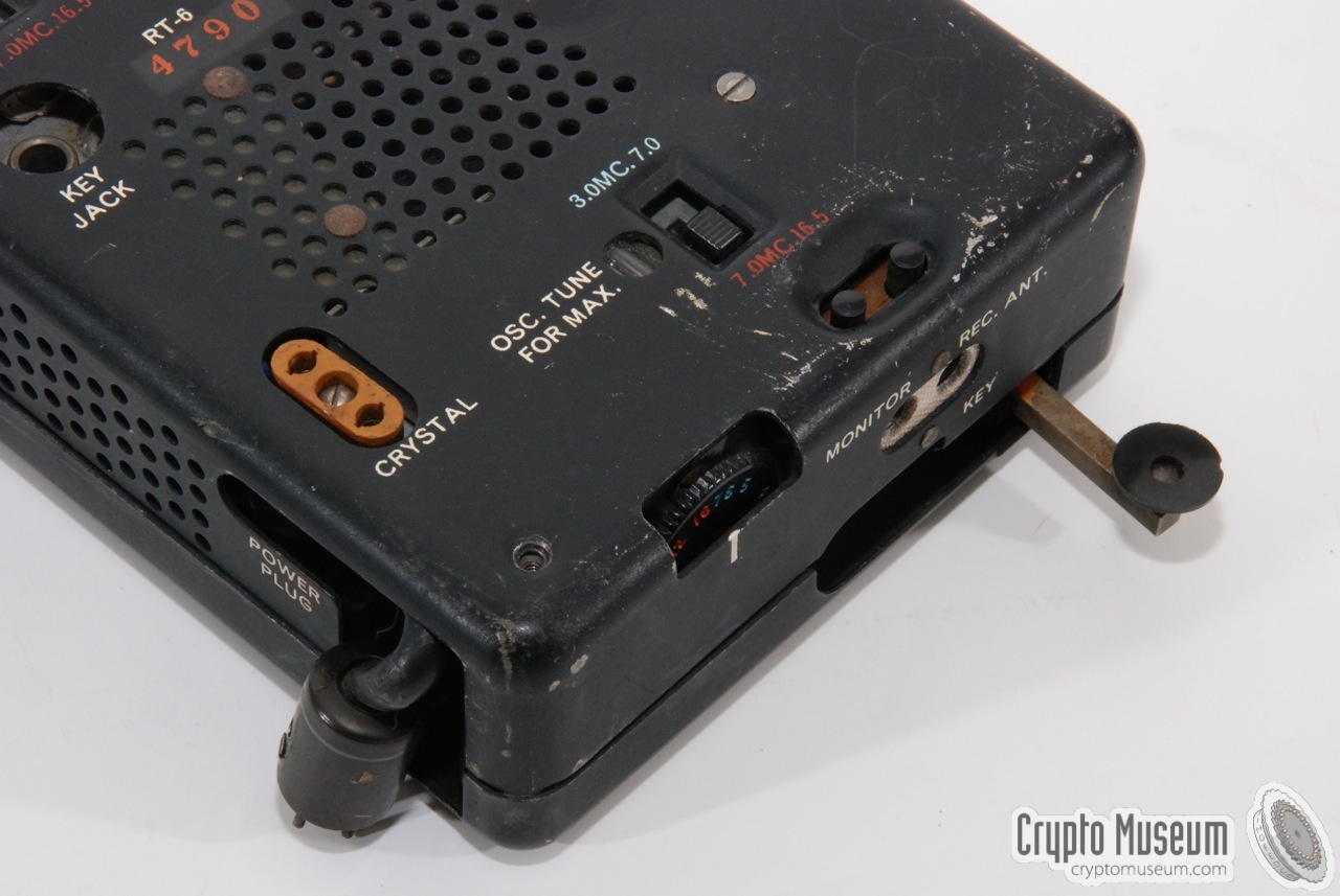
The crystal-driven transmitter (RT-6) covers 3-16MHz,
divided over 2 ranges (3-7MHz and 7-16.5MHz)
with a maximum power output of 10W.
It has a built-in keying relay that can be used up to 40wpm
(words per minute) when operating the internal key
or an externally connected key.
When used with an automated keyer, the cathodes of the valves would be
driven directly, allowing speeds up to 60wpm.
The power supply unit (PSU, RP-6) is suitable for a wide range of mains (AC)
voltages (70, 95, 120, 150, 190, 230 and 270V) so that the RS-6 could be used
practically anywhere in the world. The PSU is based around a 6X4 valve
instead of the selenium rectifiers that were used in the RS-1, probably to
save space.
It also contains a built-in vibrator, allowing the PSU to be used as a
power inverter when operating from batteries or a hand-crank generator (GN-58).
|
- Standard version RS-6
The standard version of the RS-6 was produced from 1951 onwards,
and was succeeded by the enhanced RS-6A in 1953. Most of the surviving
RS-6 units are of this type.
- Extended version RS-6A
In 1953, the frequency range of the RS-6 was expanded up to 22 MHz.
The enhanced version was known as RS-6A. It was in production
until 1954, but in much lower quantities than the standard RS-6.
RS-6A units are extremely rare.
- Stay-behind version RS-6/NL
This is bascially the standard RS-6, which was modified for use
by the Dutch Stay-Behind Organisation O&I.
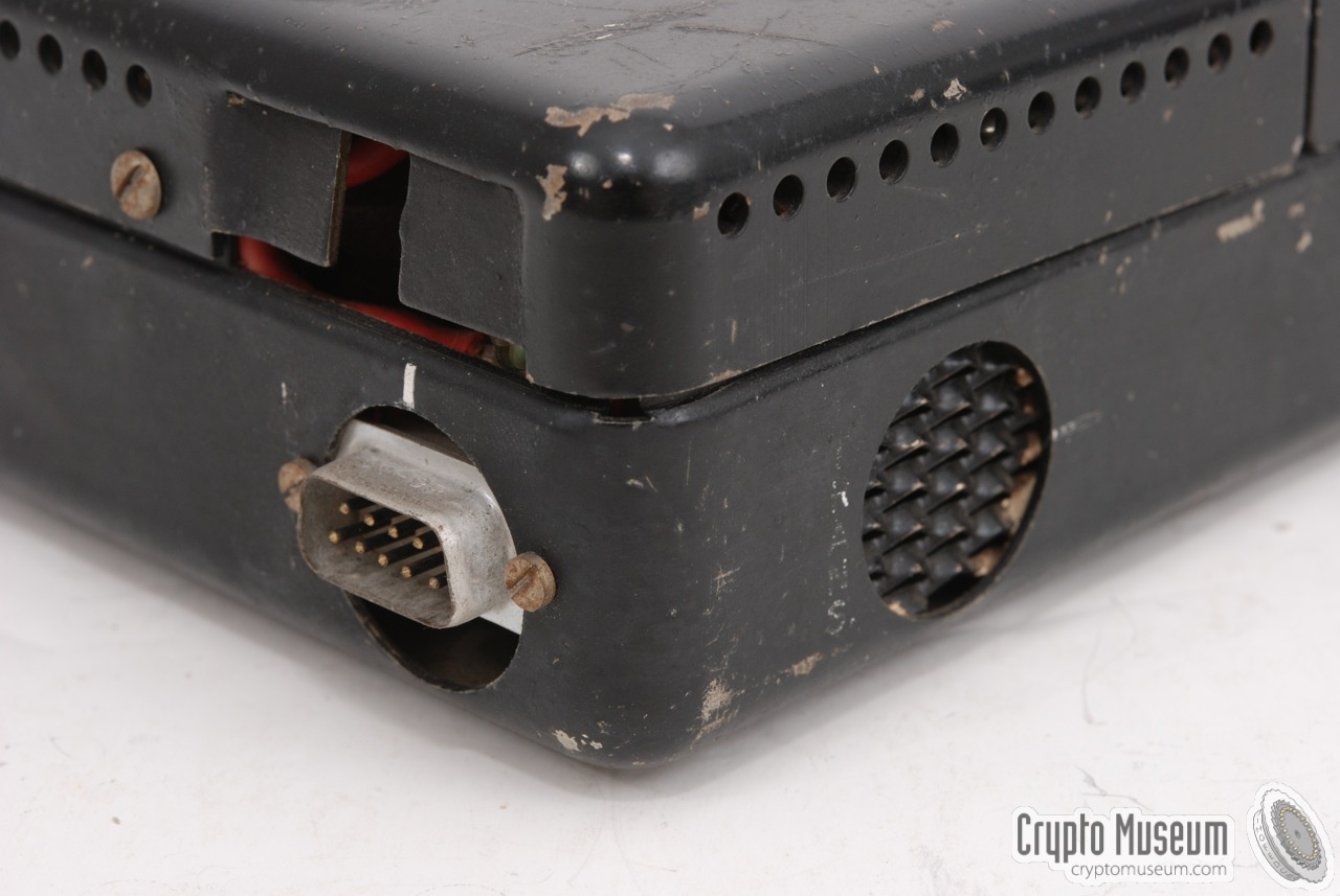
The circular connectors were replaced by the more common
9-pin DE9 connectors, and the
mechanical vibrator was replaced by an electronic one.
- All-in-one version RS-511
Especially for the CIA, an all-in-one version of the RS-6 was
produced, in which all parts are housed in a single briefcase,
The device is known as RS-511
and comprises an integrated
CK-8 (GRA-71) burst encoder.
|
Production of the RS-6 started in 1951 and they were manufactured until
1953 when a slighty improved version with an extended frequency range
(RS-6A) was introduced. Production of the RS-6A went on until 1954.
It is estimated that in-all approximately 10,000 RS-6 units were built.
The CIA also developed a single-case version of the RS-6, called the
RS-511, which is basically just a single front panel with the four
RS-6 units behind it. This unit is described in Keith Milton's book
Ultimate Spy
[2]
.
|
|
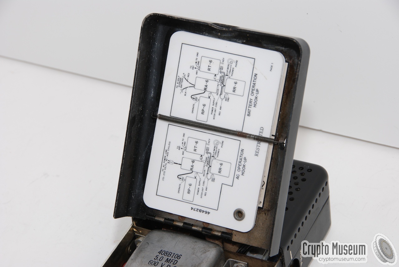
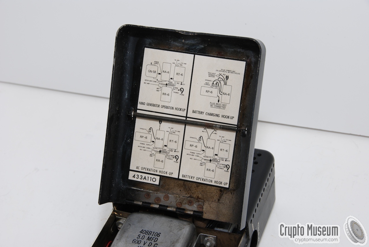
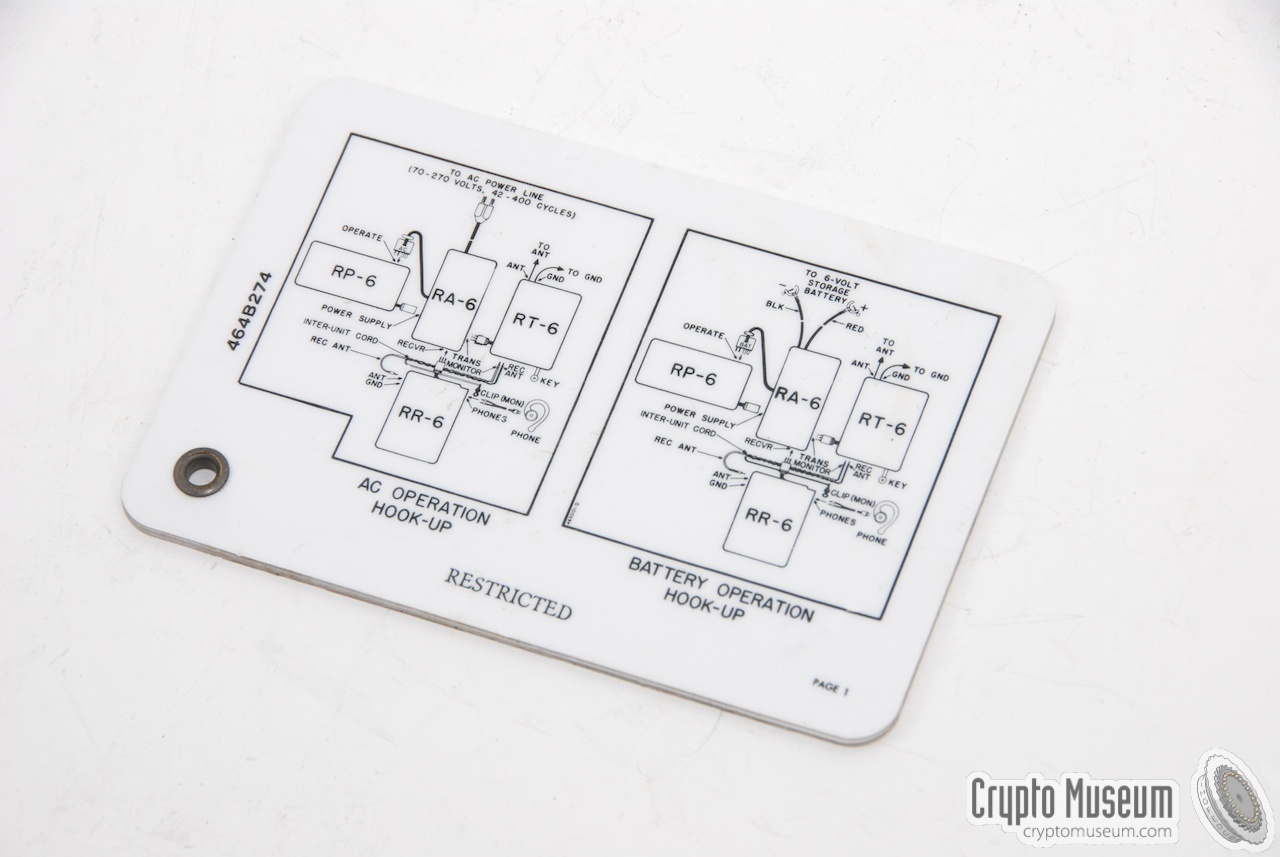
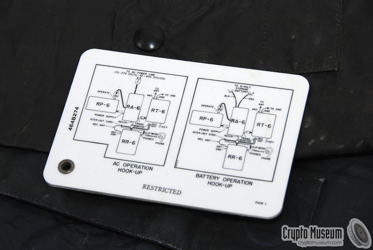
The RS-6 radio set can be used in a variety of ways. The different
configurations are described in a small set of plastic cards and
on a sheet affixed to the inside of the top lid of the power adapter.
By using the four major components in different combinations,
it can be used for any of the following setups:
|
- AC mains powered radio set
- Battery powered radio set
- Mains battery charger
- Hand generator powered radio set
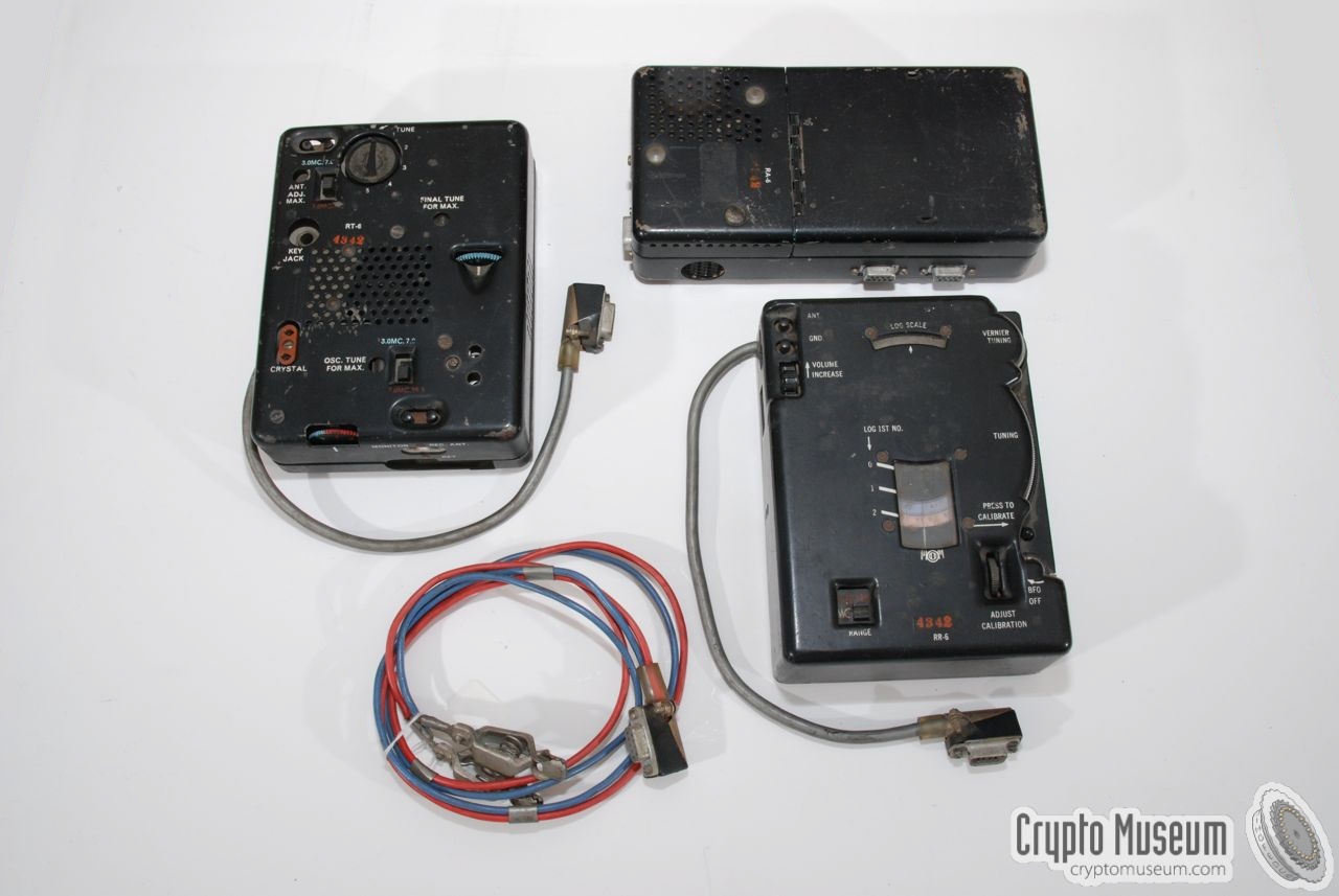
The image on the right show a typical setup of the four units.
In this case, it's a AC mains powered radio set.
The mains (AC) power supply is at the top left.
To the right of it (at the centre) is the power adapter.
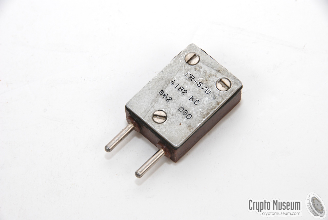
At the right is the transmitter, shown here witha crystal on top.
The unit at the front is the receiver.
The plastic cards with the circuit diagram are on the left.
|
|
|
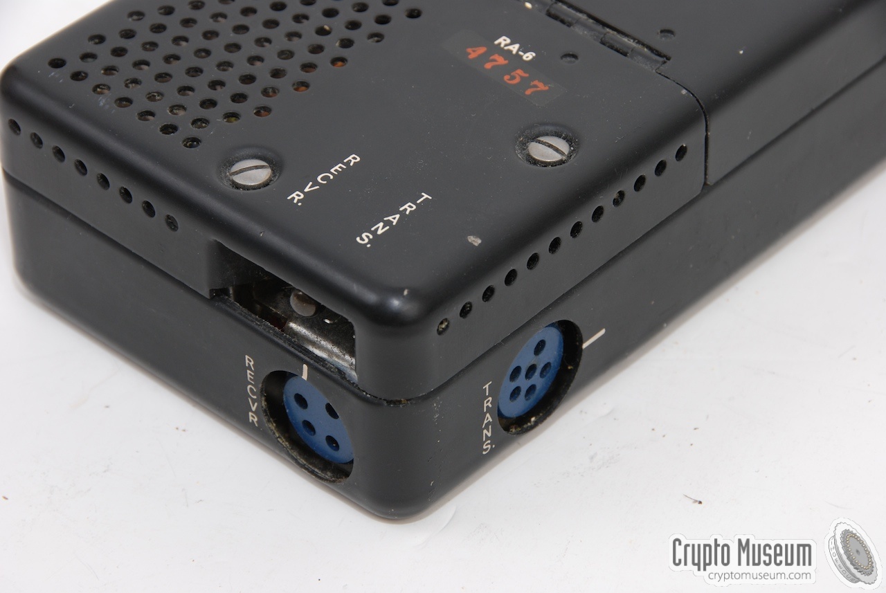
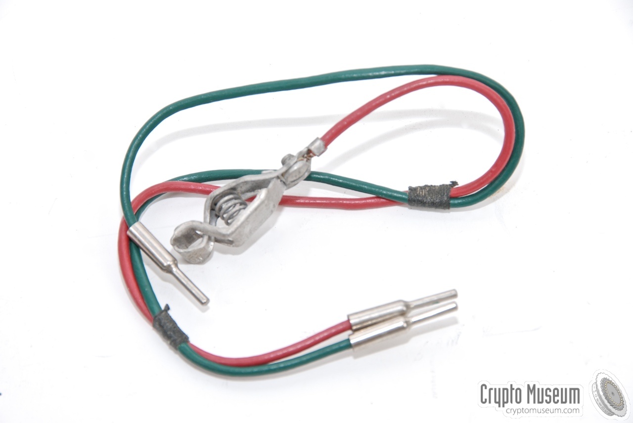
The power adapter RA-6 acts as a junction box, as it connects all
units together. Each of the other three units connect to the
power adapter by means of a multi-pin circular plug.
The antenna and ground wires are connected to the transmitter only.
The antenna wire is just visible at the top right of the image above.
A so-called inter-unit cord is used to loop the antenna to the
receiver (the red/green wire at the centre). This cable is also used
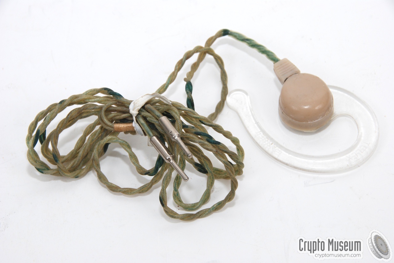
for the side tone. A small earpiece is connected to the side of the
receiver.
|
Modified by Dutch stay-behind organisation
Initially the RS-6 was build exclusively for use by the CIA, but at some
point the Strategic Air Command (SAC) started ordering large quantities
for use aboard some of their aircraft for certain types of missions.
The RS-6 was also used for clandestine operations and Stay-Behind.
|
Recent discoveries have shown that the RS-6 was also used by the secret
services of some friendly nations, such as The Netherlands.
The RS-6 was ordered by the Dutch Intelligence Agency
(Binnenlandse Veiligheidsdienst, BVD, now AIVD)
for the Dutch
O&I
stay-behind organisation
(sometimes referred to as Gladio).
As the circular connectors were rather difficult to obtain in The Netherlands,
the units were modified with 9-way sub-D type connectors that were
commonly available in Europe at the time.
|
|
|
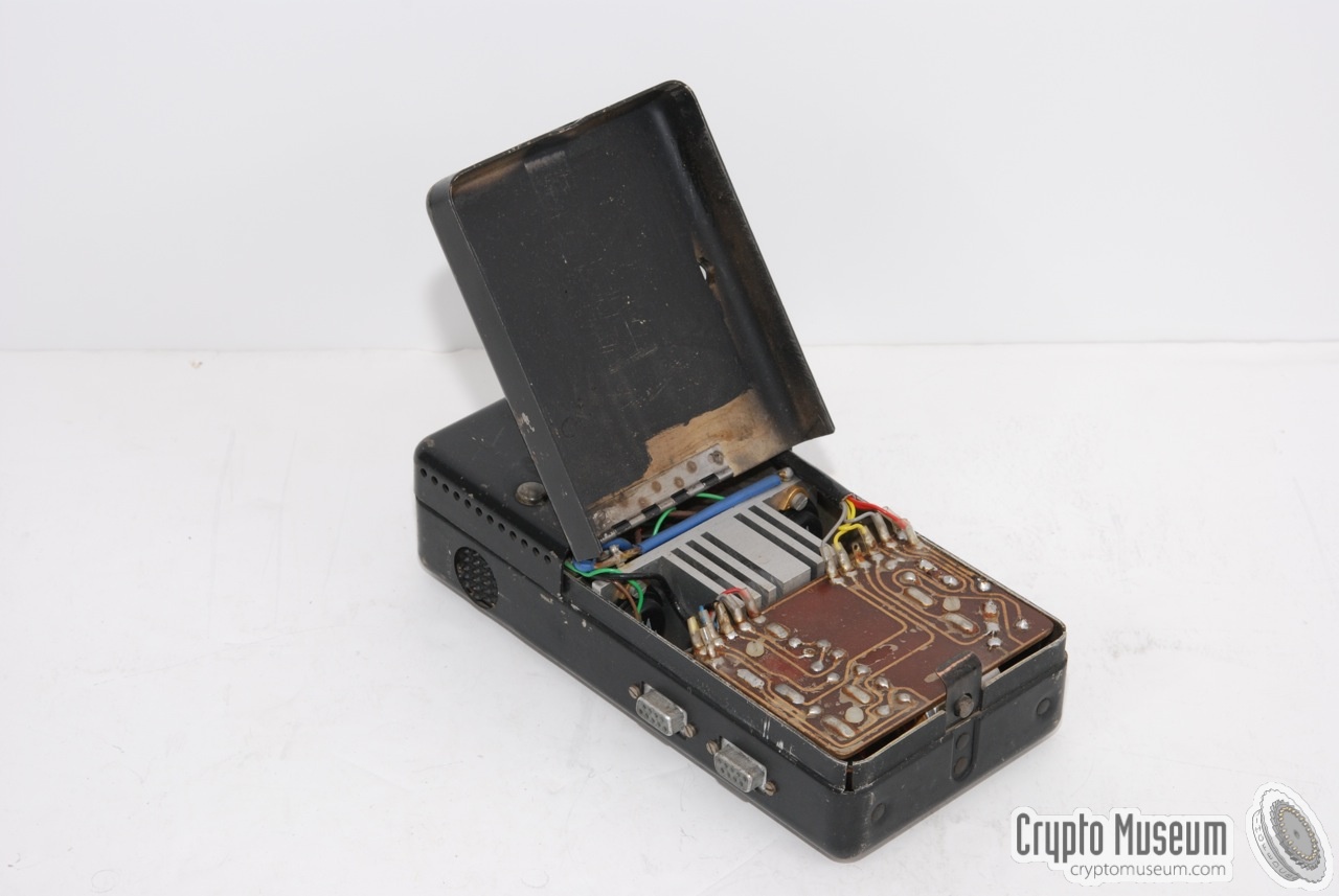
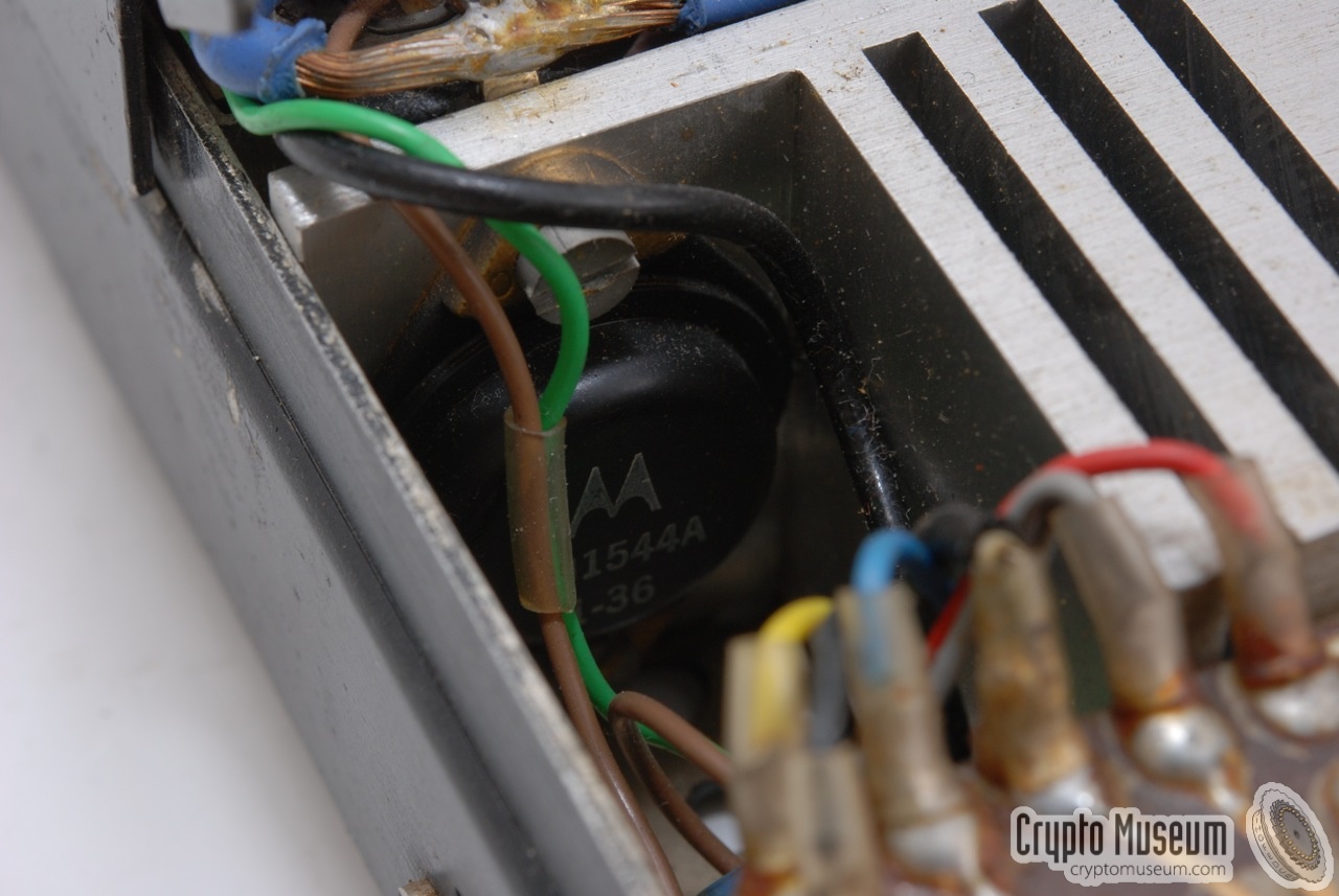
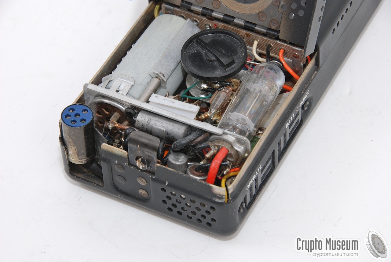
Furthermore, the mechanical vibrator-based inverter was replaced
at some point by an electronic circuit, which made it far more reliable.
The new electronic inverter was build inside the empty compartment of the
Filter Accessory Unit (RA-6).
|
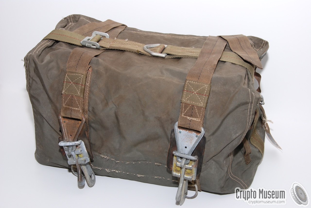
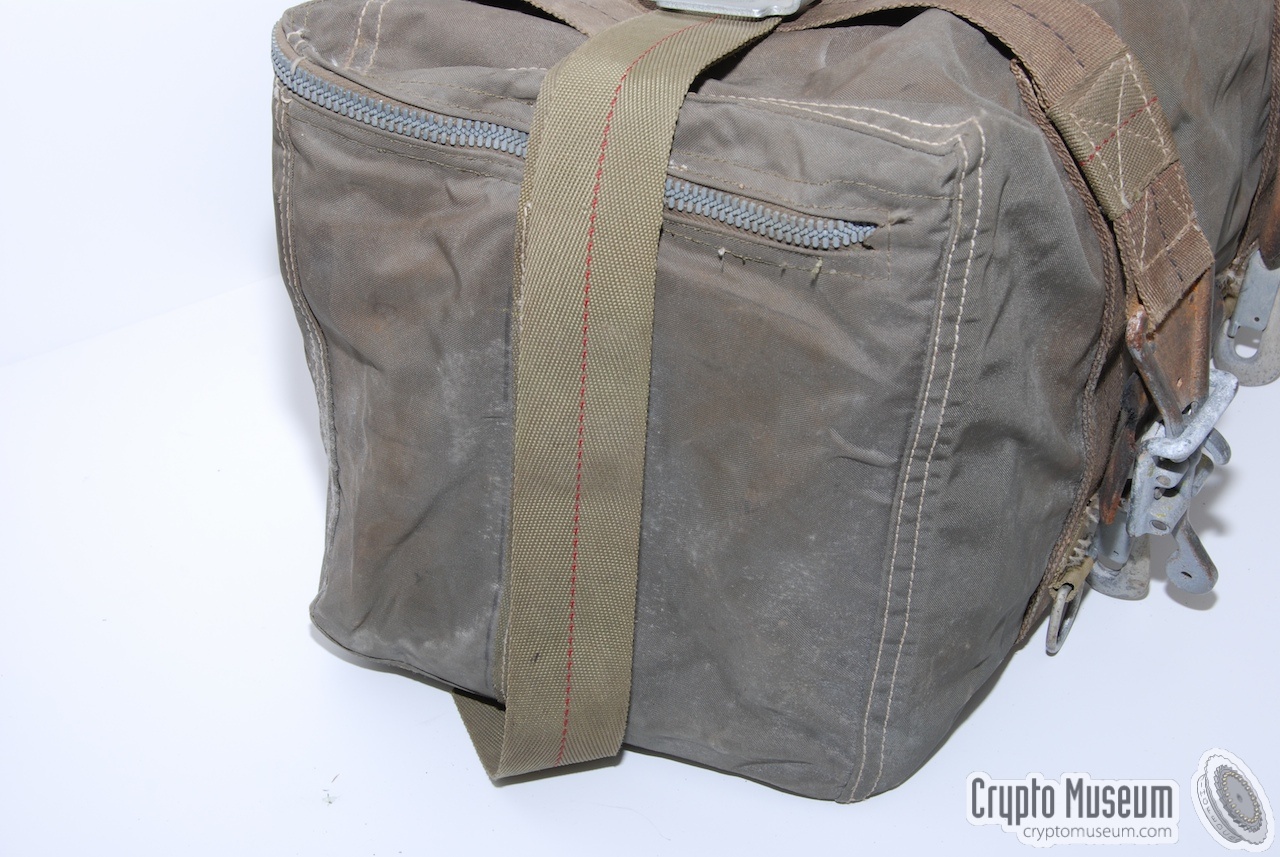
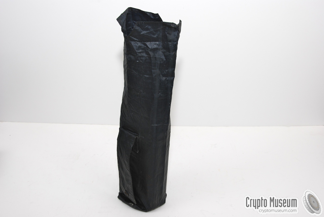
The complete RS-6 radio set was sometimes stored in this military-issue
canvas carrying bag, such as the one shown here.
The bag is large enough to hold all units, cables, the GN-58 generator, etc.
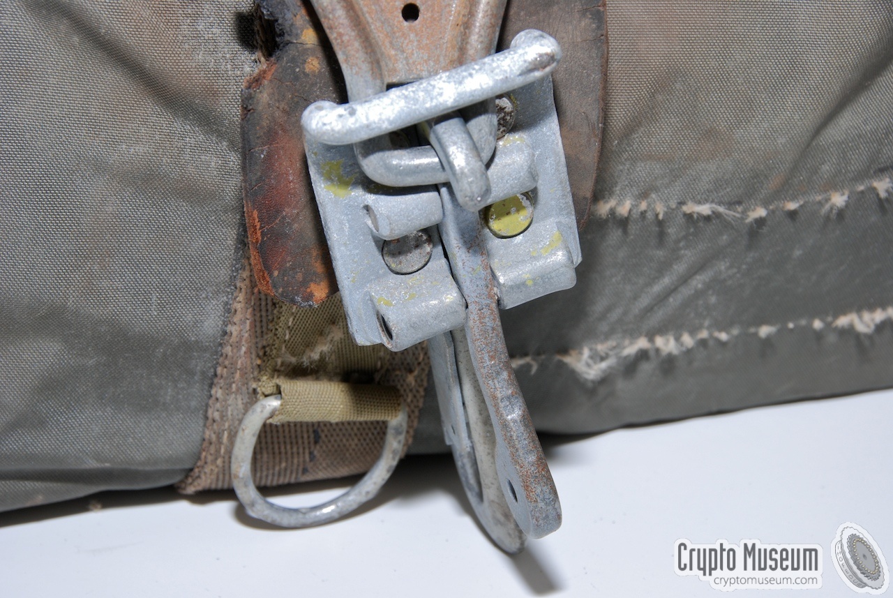
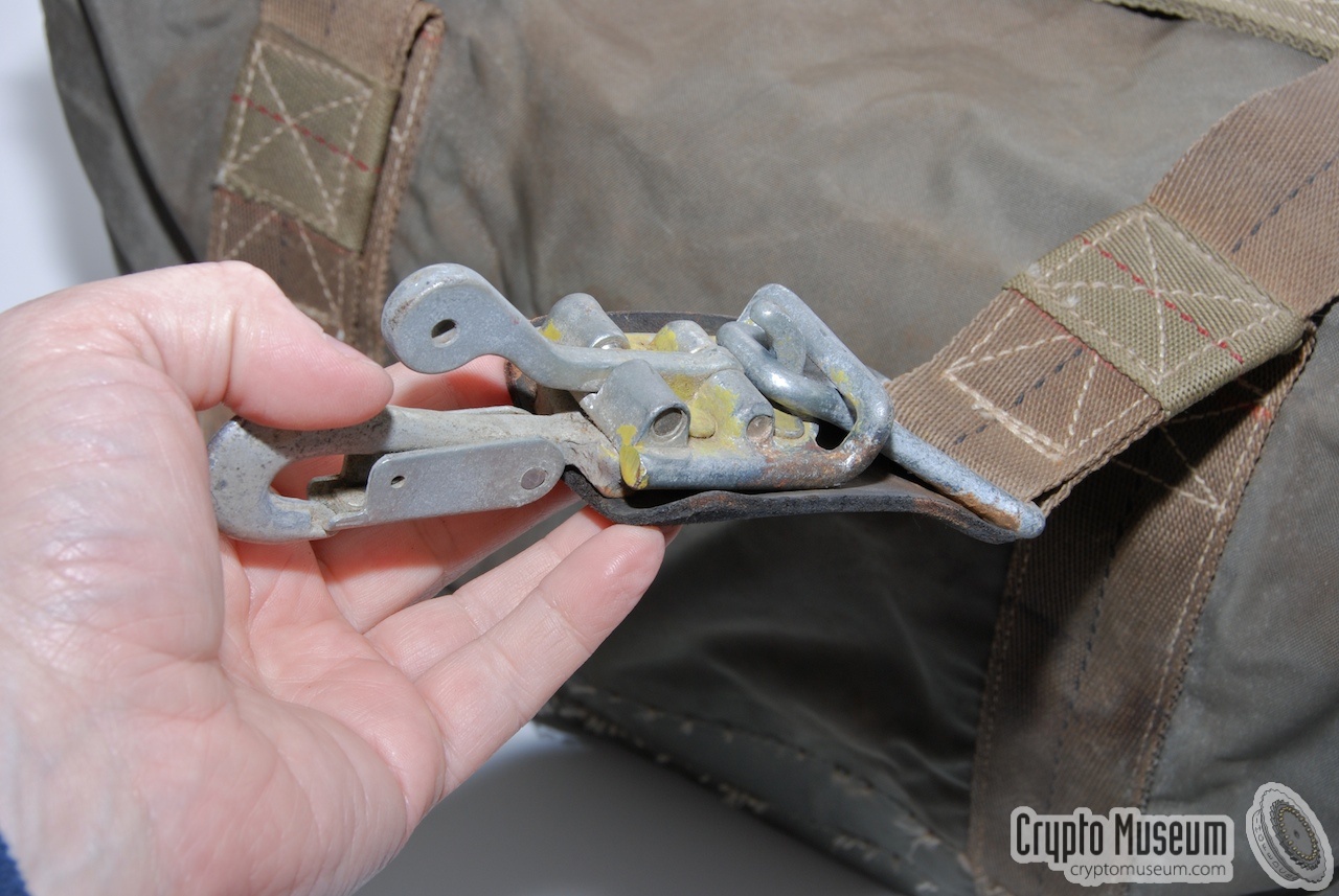
Various straps are attached to the bag, allowing it to be closed firmly.
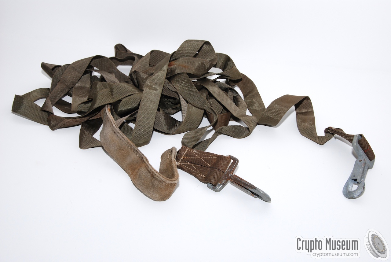
An additional 9 meter long strap with hooks at both ends allows
the bag to be lowered in a building, shaft, bunker, etc.
|
|
|
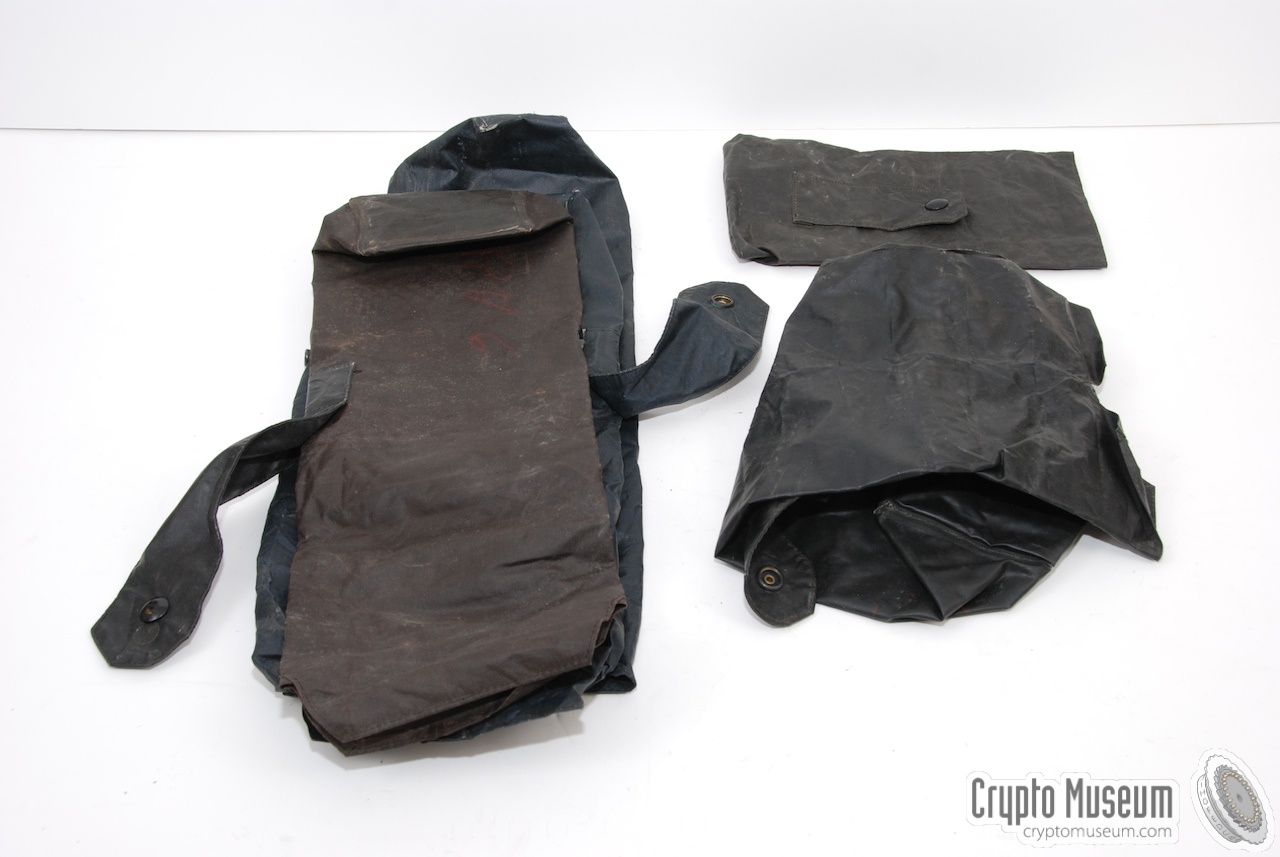
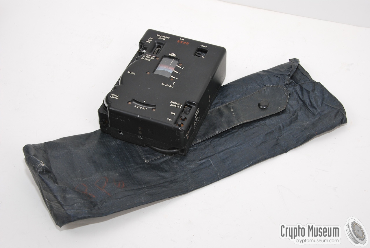
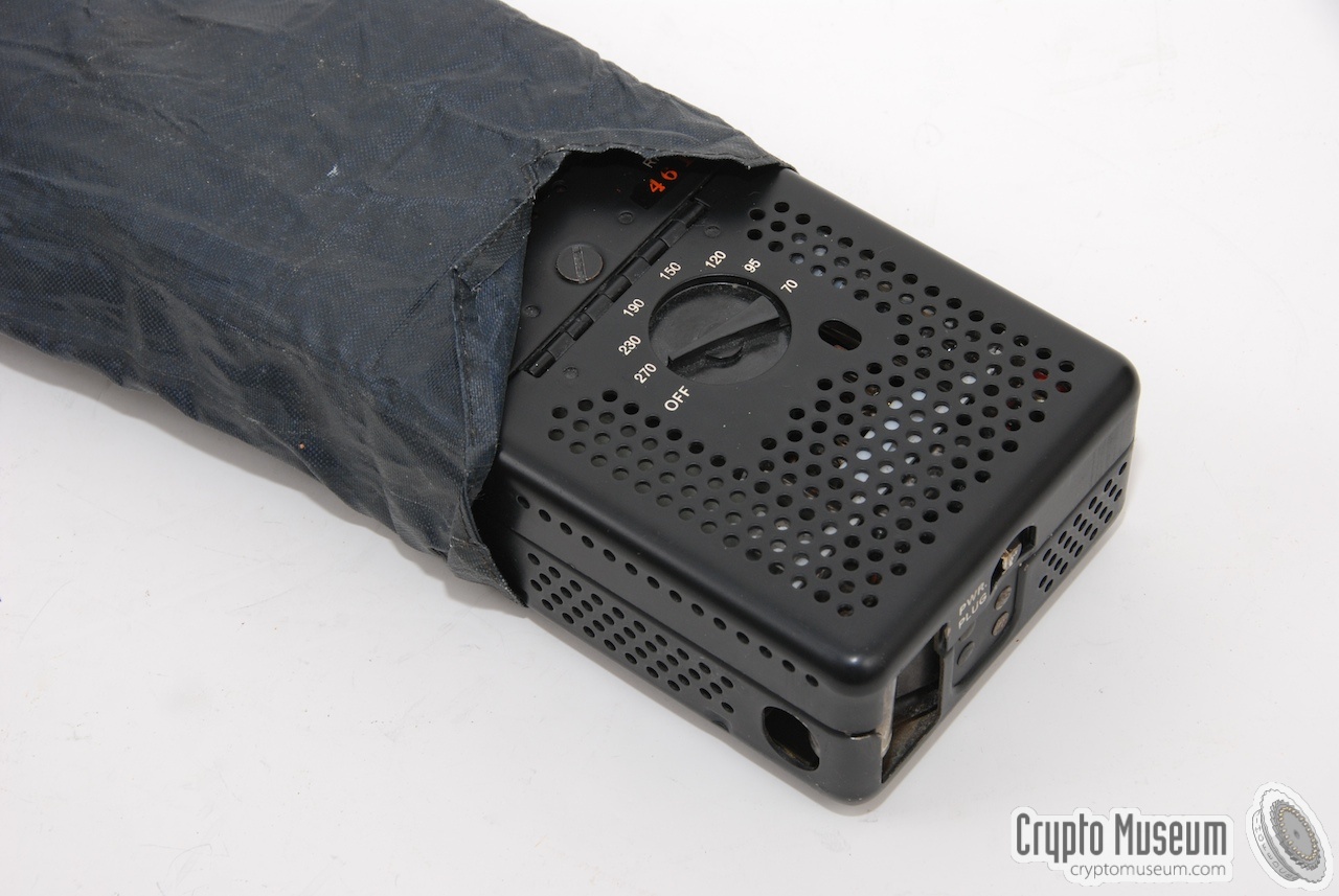
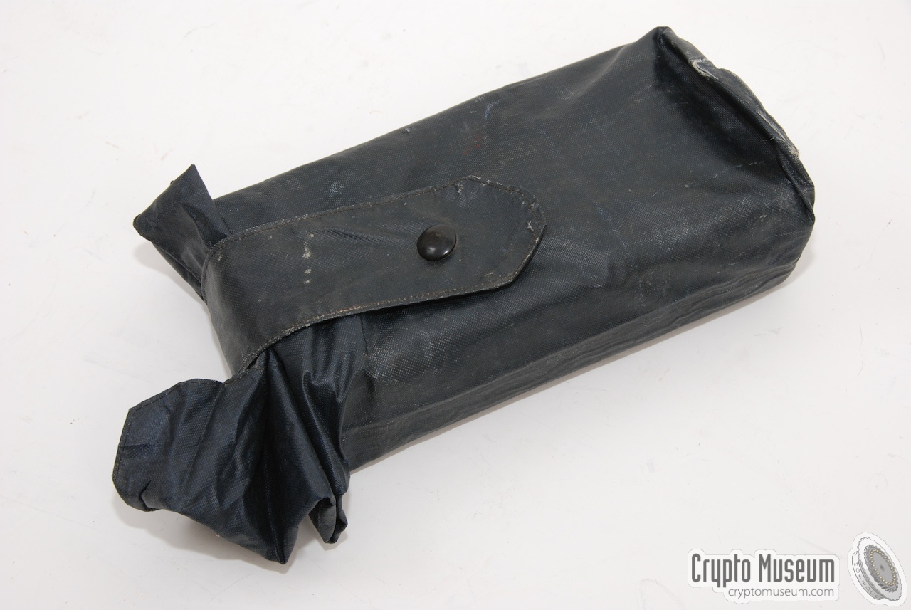
The four units of the RS-6 were often packed inside a set of canvas/plastic bags
to protect them agains water and dirt. Special packaging instructions were supplied
in the instruction booklet.
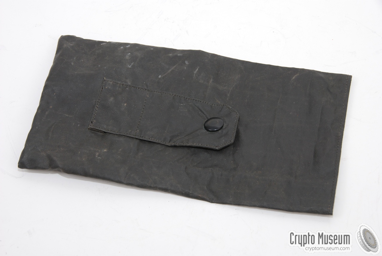
Each bag is actually a long 'sleeve' that tightly fits the unit. The surplus end of
the sleeve is folded like a harmonica and a strap is used to keep the lot in place.
The images below show the correct way of packing a unit.
|
|
|
The transmitter covers a frequency span of 3-16 MHz, in two ranges,
and is crystal operated. The maximum power output is 10 Watt.
The built-in morse key can be used for speeds up to 40 wpm (words per minute).
When using an automated keyer or a burst encoder, speeds up to 60 wpm are
possible. In the latter case, the cathodes of the valves are driven
directly.
|
|
|
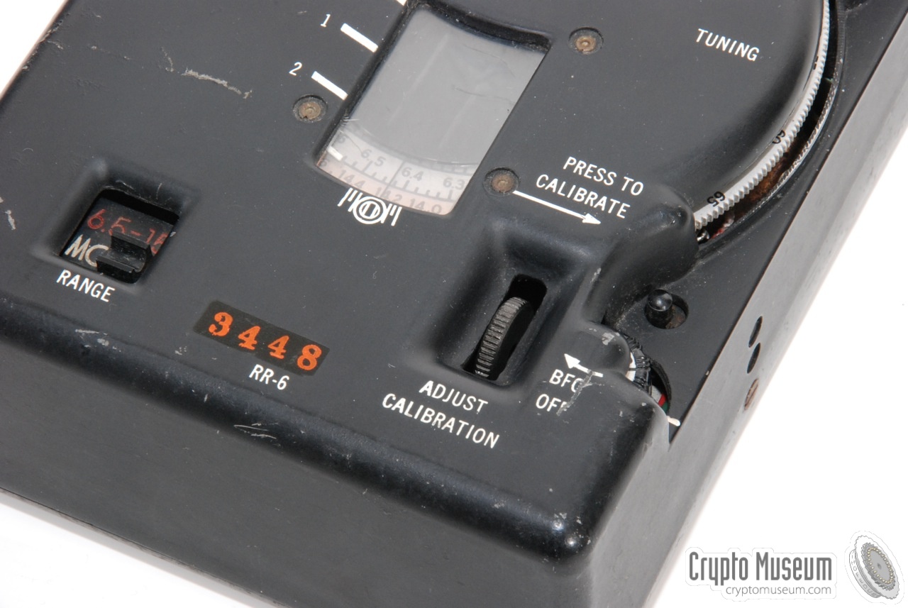
The receiver convers approx. the same frequency ranges as the transmitter.
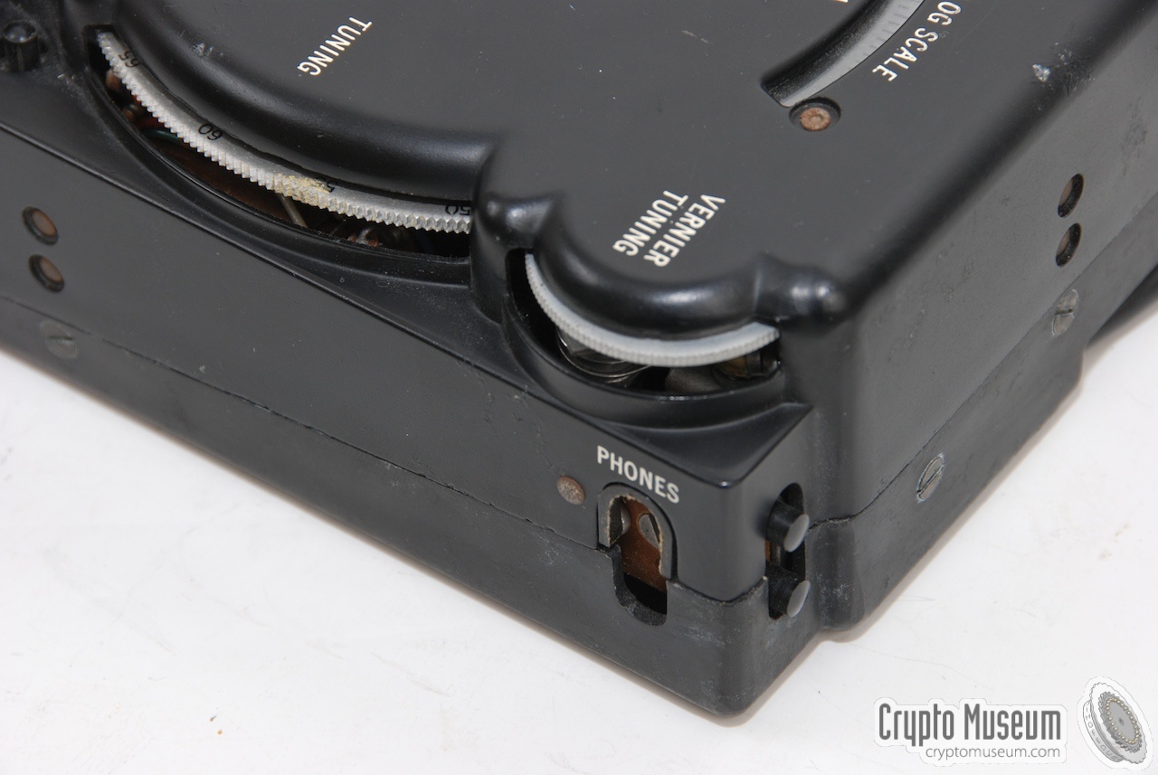
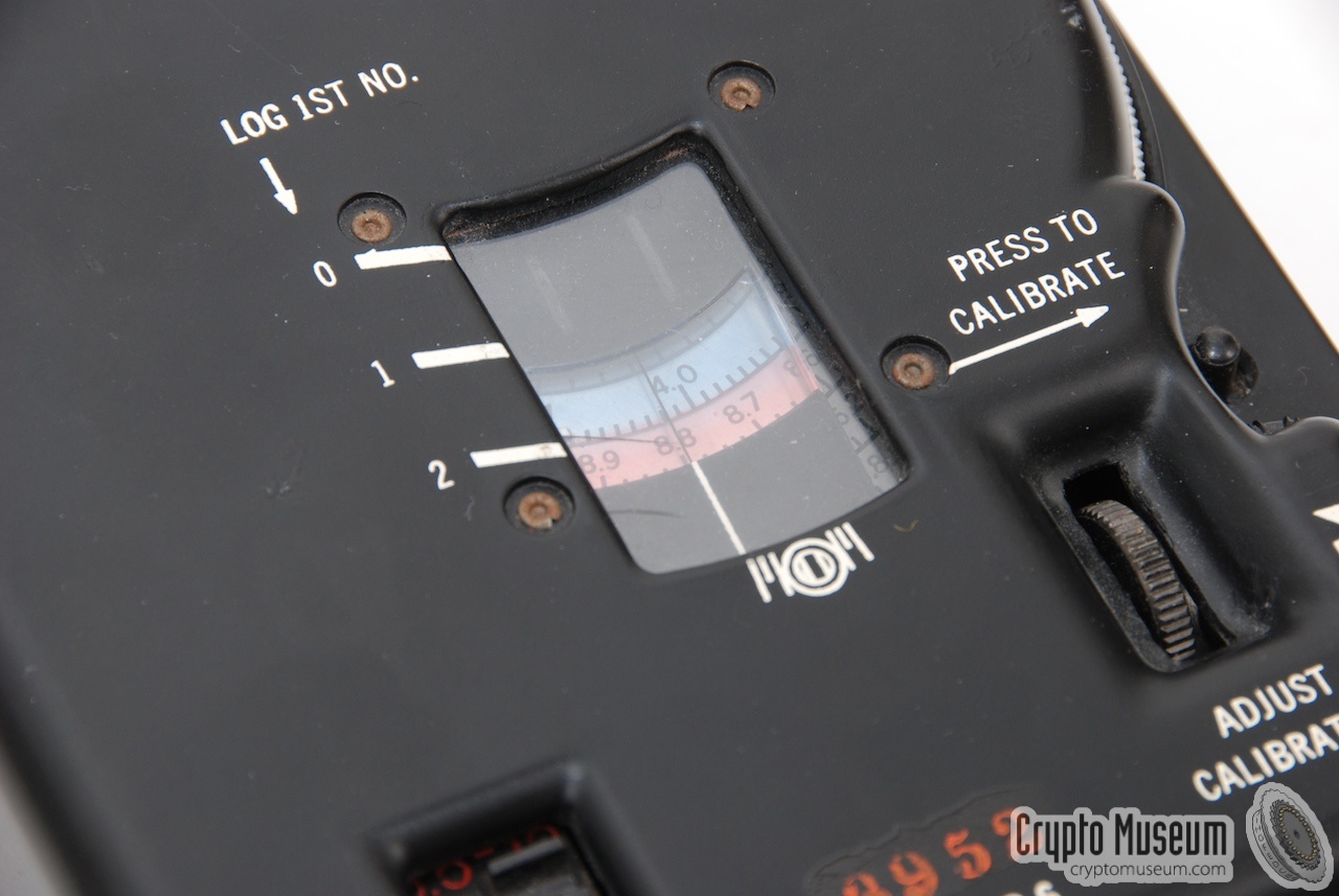
It has a beautifully shaped die-cast aluminium body with an integrated
frequency adjustment scale.
The big dial is used for coarse adjustement,
whilst a smaller thumbwheel (at the top right) allows fine tuning.
|
|
|
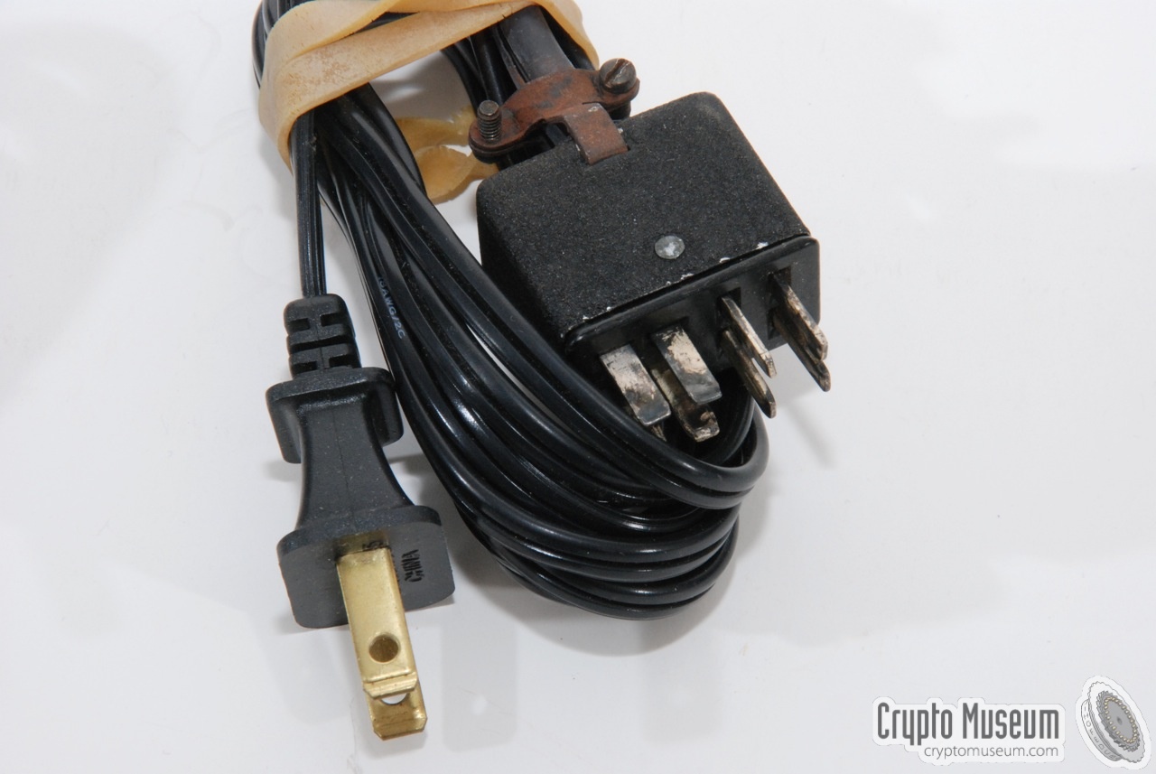
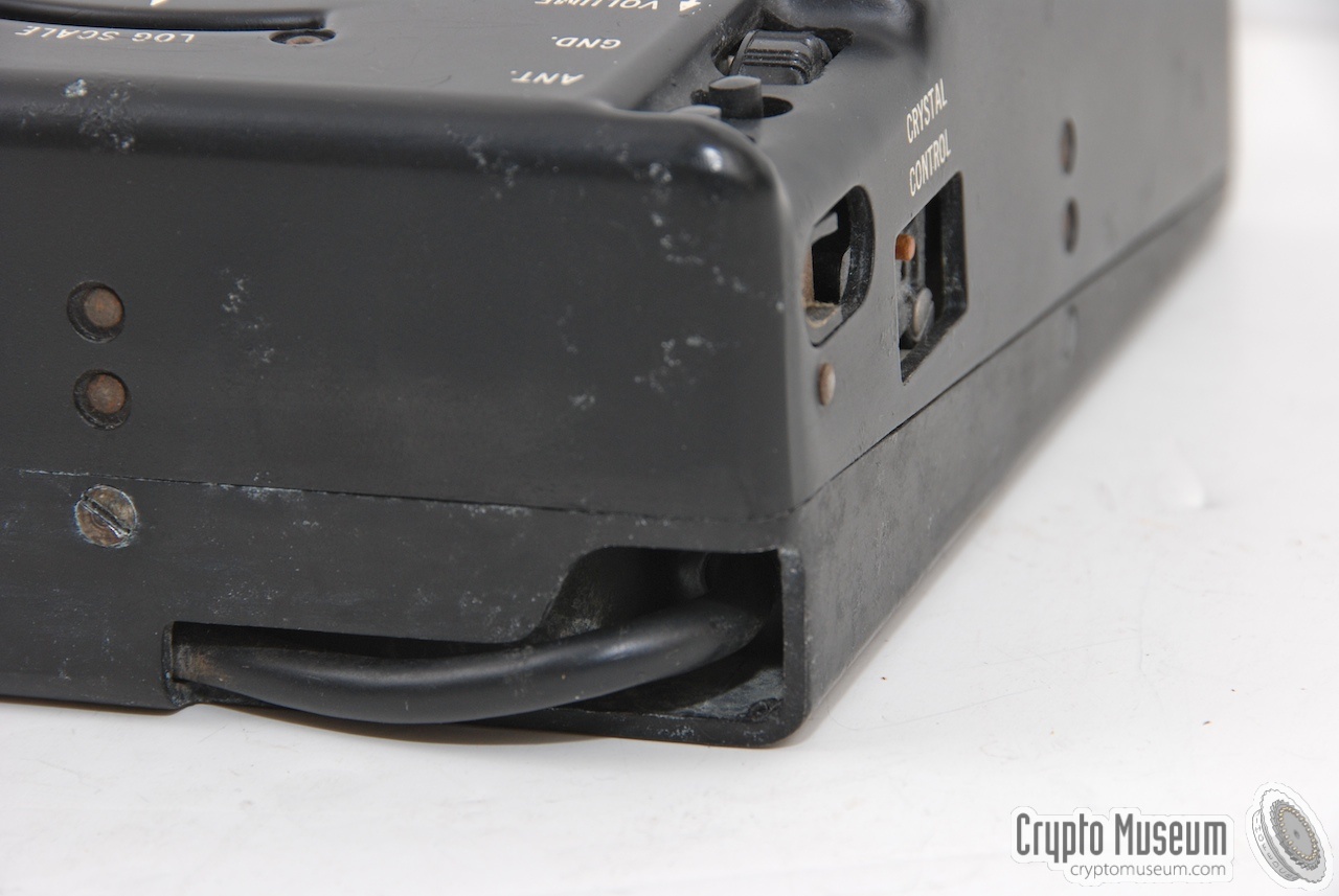
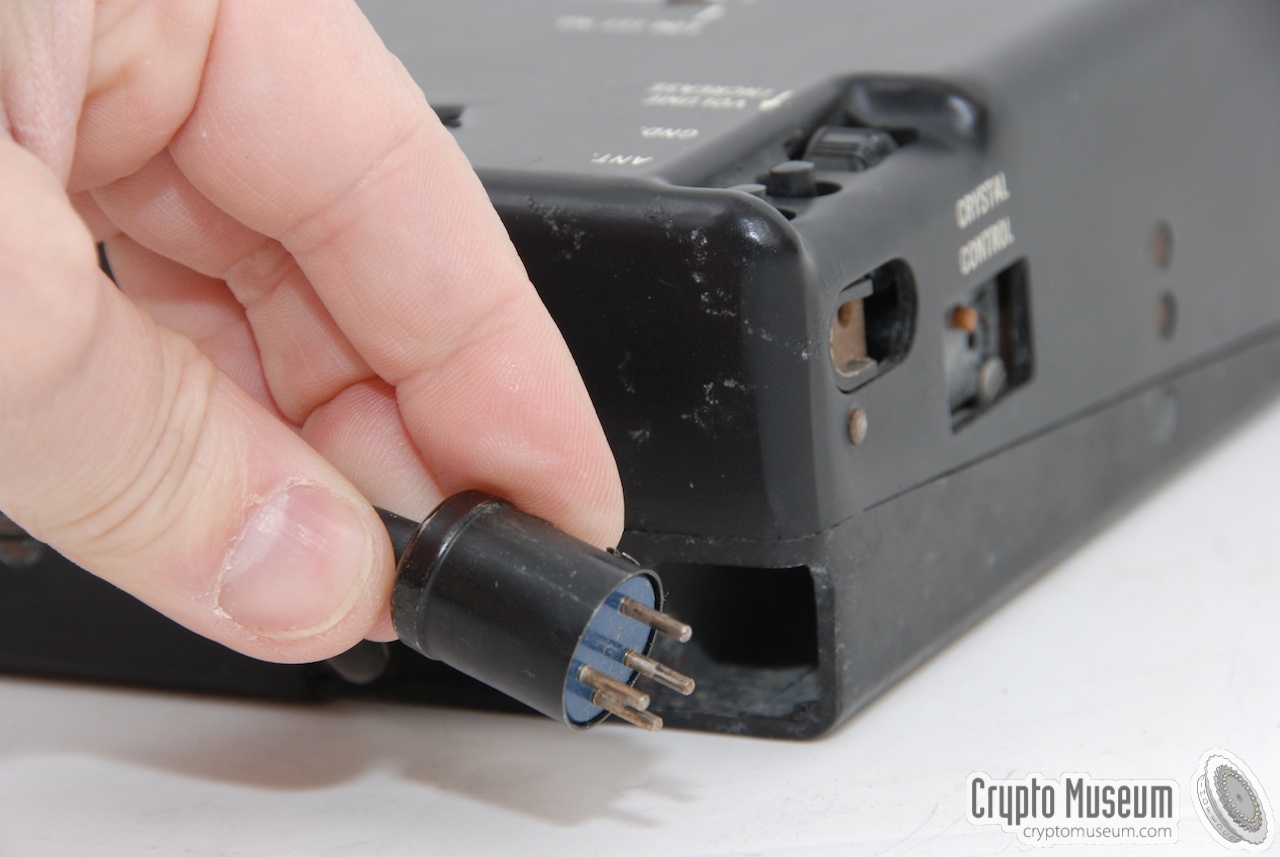
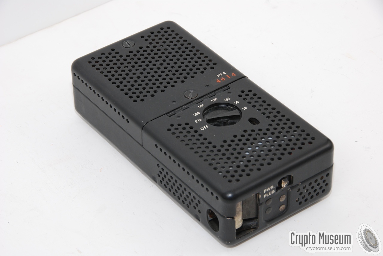
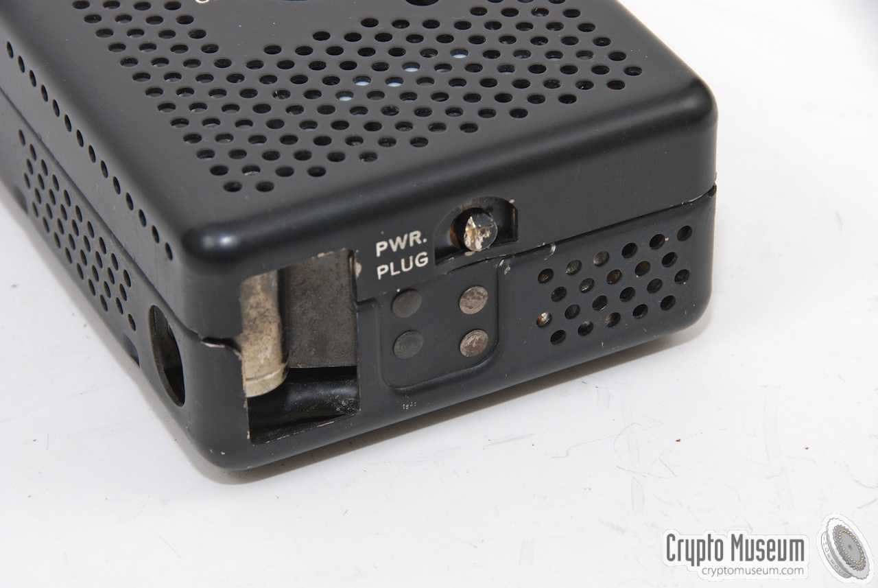
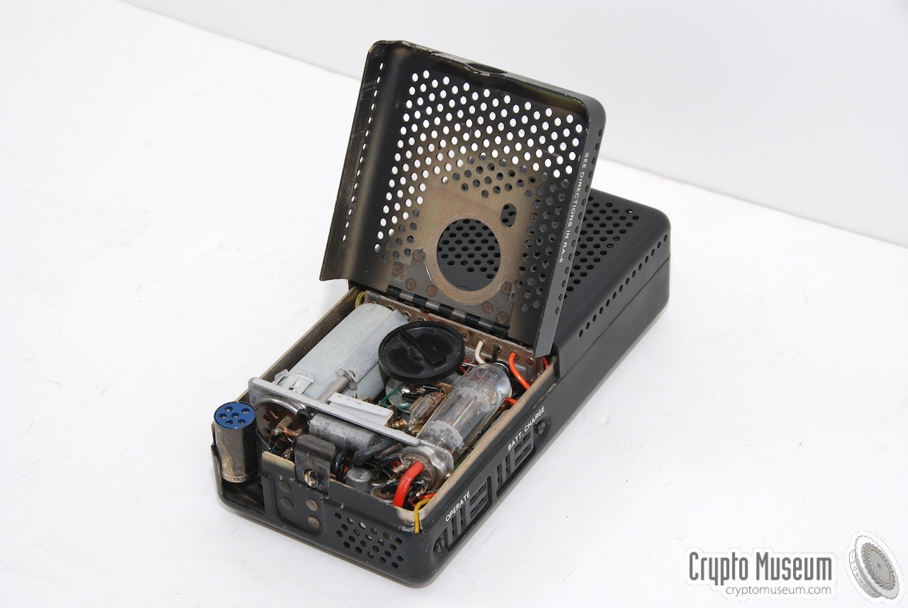
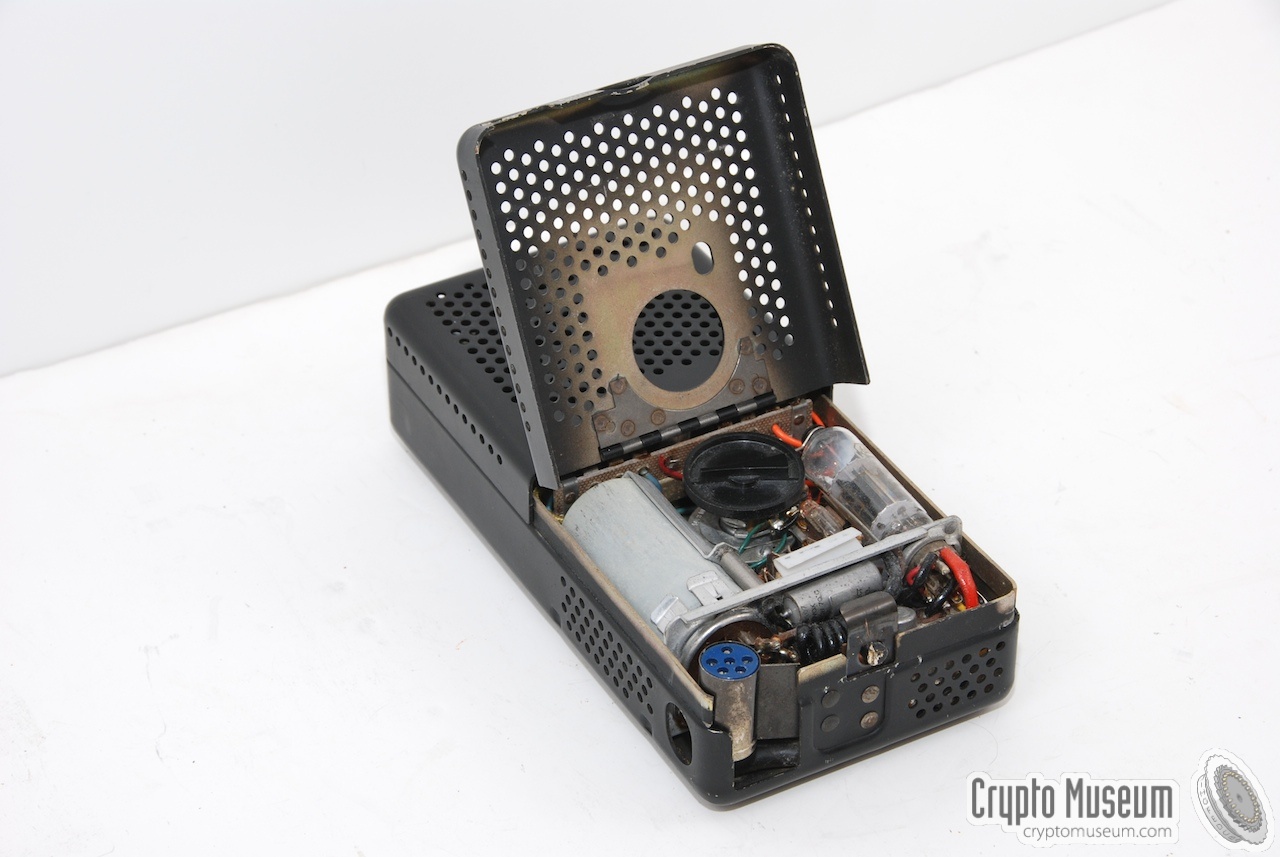
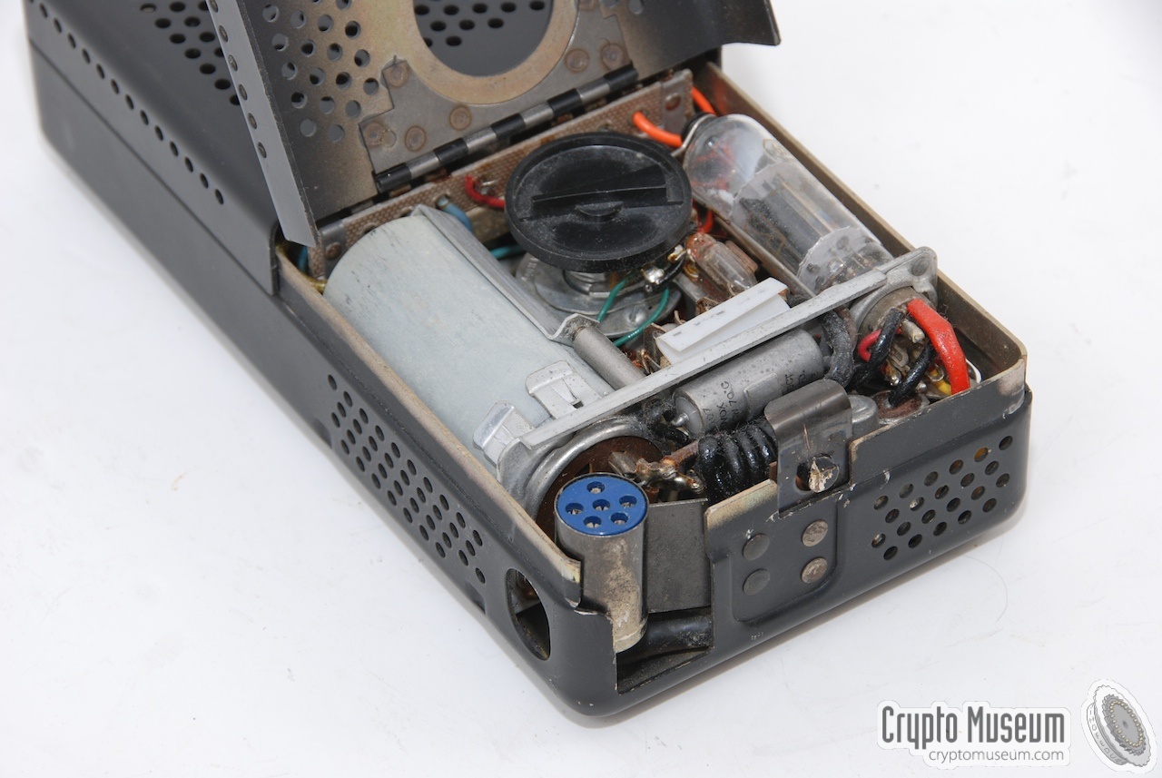
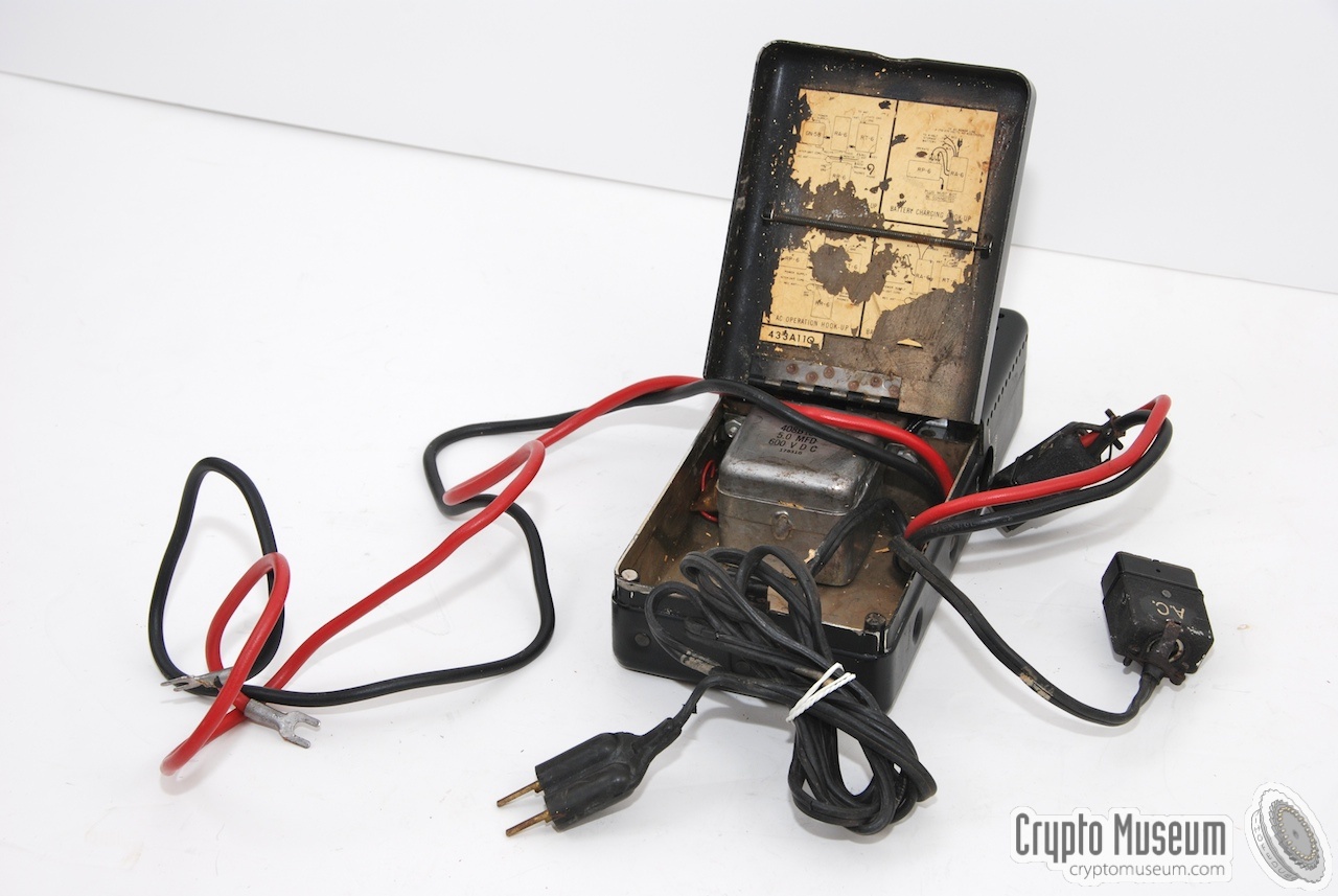
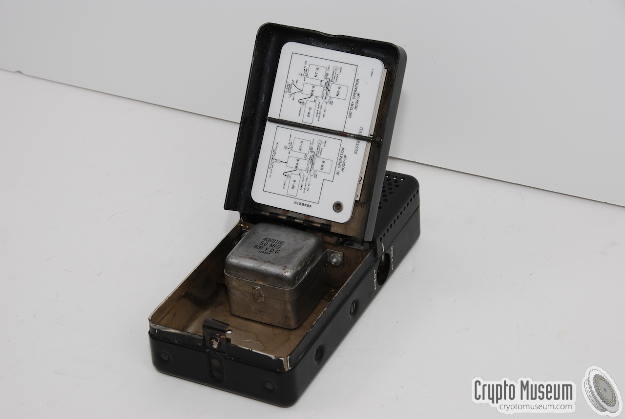
The RP-6 power supply unit allows the RS-6 to be used with a variety of
mains voltages, from 70 to 270 Volt AC. As the unit contains a
power inverter (vibrator) it also allows operation from a standard 6 Volt
DC car battery.
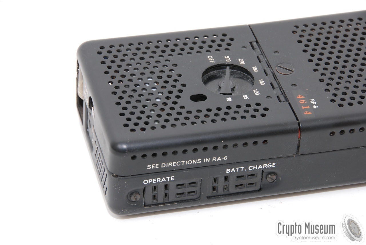
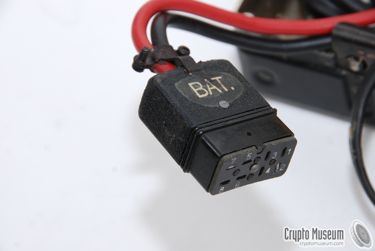
Furthermore, the RP-6 can be used to charge the battery from any mains
voltage. The connections for all three modes of operation are at the right
of the unit in the shape of two 8-pin sockets. The text just above the sockets
tells us that instructions on how tu use these connectors, can be found
inside the lid of the RA-6 filter unit.
|
|
|
|
|
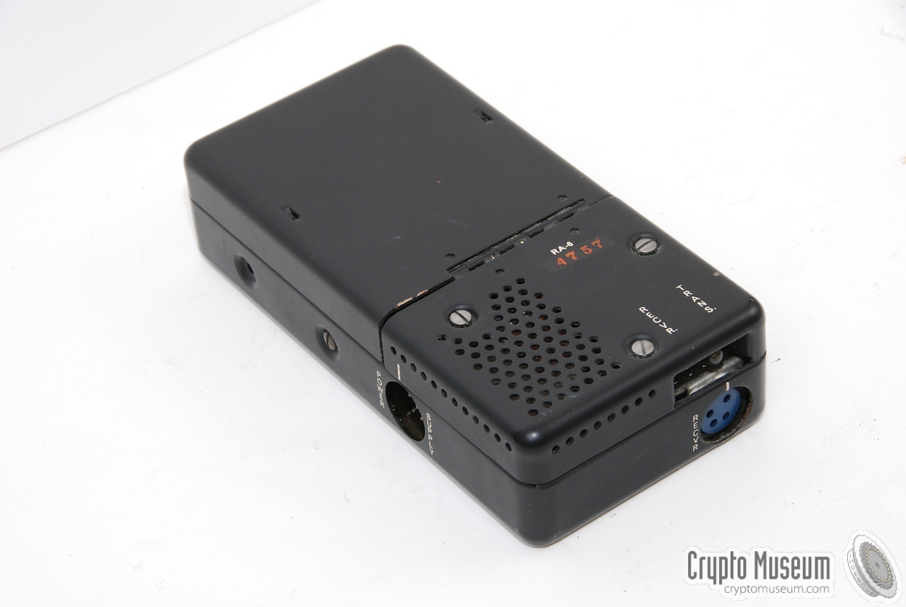
Filter Accessory Unit
RA-6
|
|
|
The RA-6 filter accessory unit basically acts as a junction box, connecting the
remaining three units together. At the same time it filters the power
lines for unwanted HF energy and excessive power surges.
Only about half of the unit is occupied by the electronic circuit,
whilst the remaining half serves as a storage unit for the power cables.
Originally, the mains and battery cables are fixed inside the cable
compartment, but as the cables have become less flexible over time, they
have been removed in most cases.
|
|
|
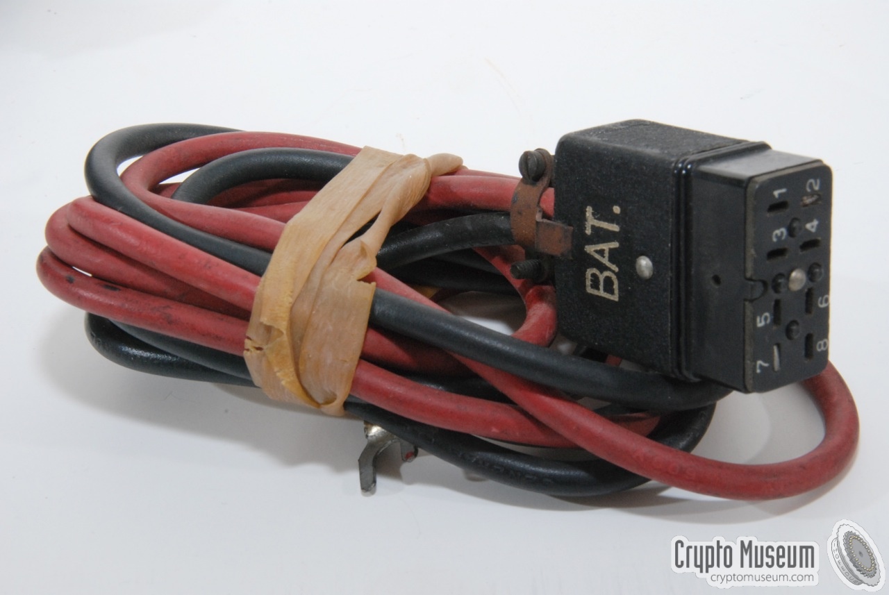
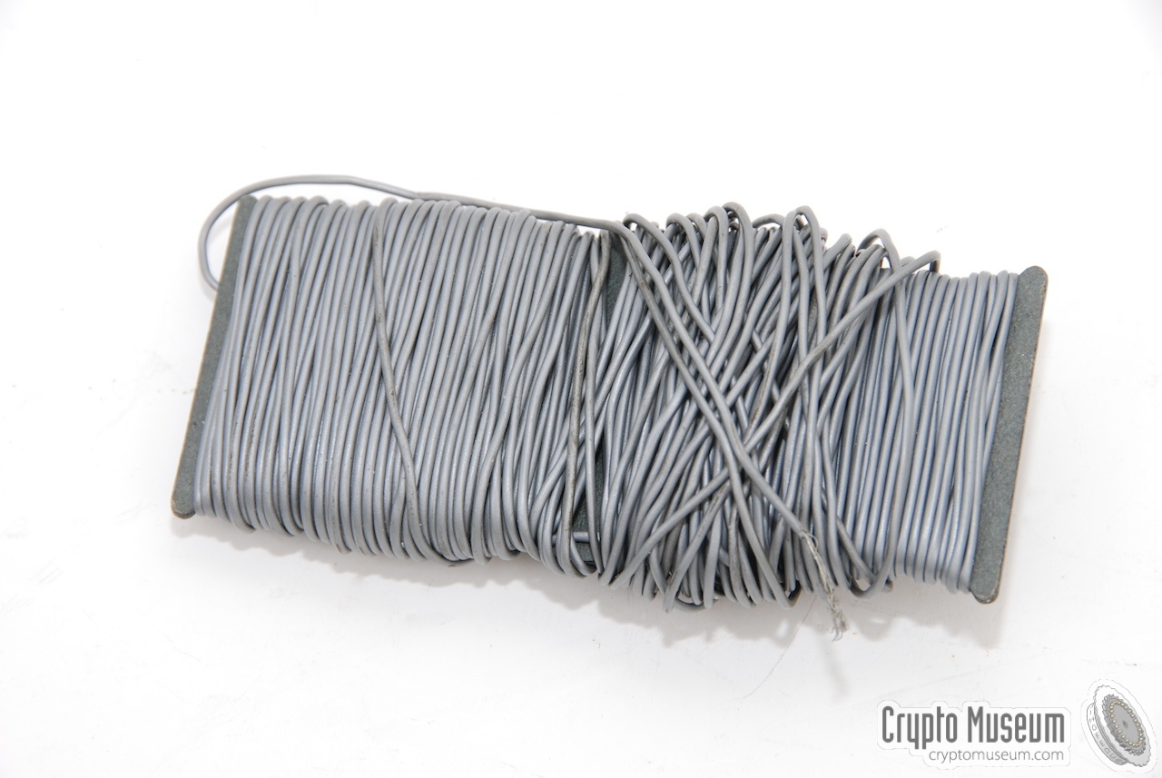
The RS-6 came with a set of small accessories, packed inside a tiny
water-tight canvas pocket. The following items were supplied:
- Interconnection cord
- One or more crystals
- Earpiece
- Two battery clamps
- Hank antenna (100 ft wire)
- Two antenna insulators
- Canvas pocket to store the items
|
|
|
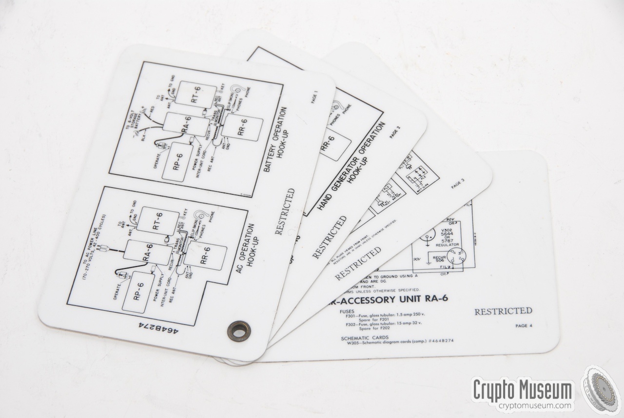
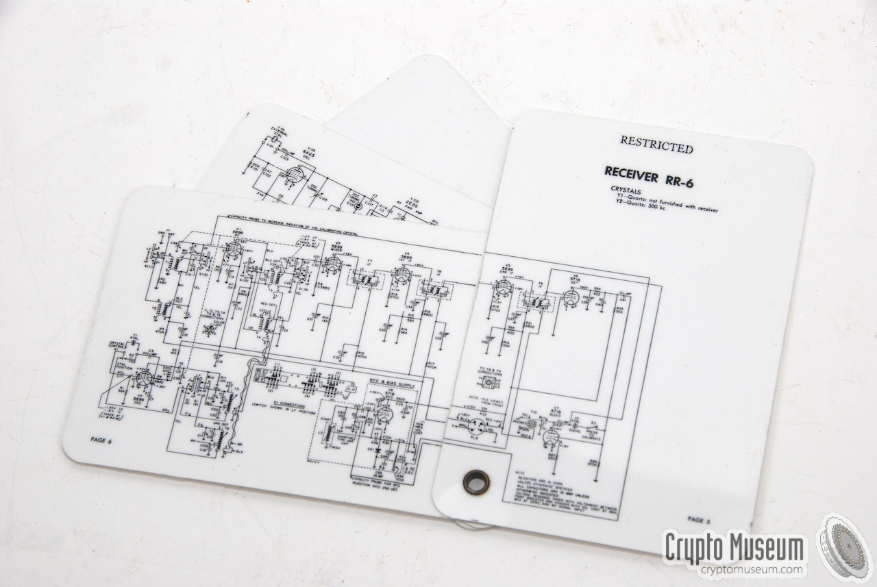
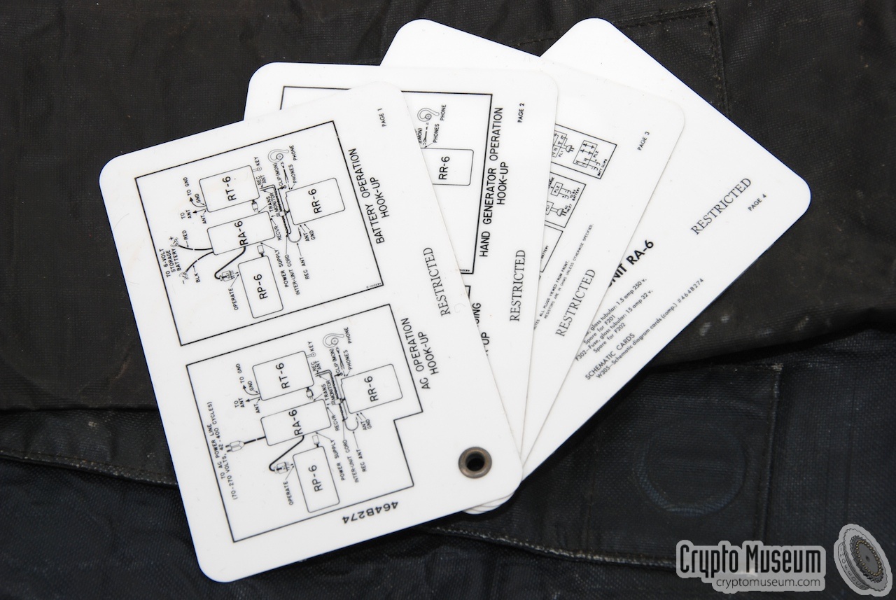
The RS-6 was supplied with a set of plastic cards containing the full circuit
diagrams and instructions on how to setup the radio for use. The cards were bound
together with a metal ring in one of the corners.
The cards were usually stored in the top lid of the RA-6 Filter Accessory Unit,
behind a metal spring.
|
|
|
The RS-6 was supplied with an extensive 44-page user manual that contains
the operating instructions as well as a technical description of the various
(sub)circuits and circuit diagrams.
In addition there is a 10-page addendum that is applicable to all devices
with a serial number of 33 or higher.
➤ Download the manual
➤ Circuit diagram only
➤ Download addendum
|
|
|
Device Spy radio set Purpose Agent communication Model RS-6 Manufacturer Motorola Year 1951 Country USA Frequency 3-16 MHz Bands 2 (see below) Waveform CW Mains 70, 95, 120, 150, 190, 230, 270V AC Battery 6V DC (vibrator) Parts 4 (see below) Dimensions see below Weight see below Quantity 10,000 ~
|
- Transmitter (RT-6)
- Receiver (RR-6)
- Power Supply Unit (RP-6) (with built-in inverter)
- Filter Accessory Unit (RA-6)
- Water tight packaging
- Accessories (see below)
- Circuit diagrams
- Manual
- Canvas carrying bag (option)
|
Frequency 3-16 MHz Bands 2 Tuning Quartz crystal Output 10 W Dimensions ? Weight ?
|
Frequency 3-16 MHz Bands 2 Sensitivity ? Dimensions ? Weight ?
|
Mains 70, 95, 120, 150, 190, 230, 270V AC Battery 6V (?DC} Dimensions ? Weight ?
|
- Interconnection cord
- Crystals
- Earpiece
- Battery clamps
- Hank antenna
- Antenna insulators
|
- 3—7 MHz
- 7—16.5 MHz (RS-6A: 7—22 MHz)
|
|
|
|
Any links shown in red are currently unavailable.
If you like the information on this website, why not make a donation?
© Crypto Museum. Created: Saturday 03 October 2009. Last changed: Tuesday, 03 March 2026 - 08:39 CET.
|
 |

|
|
|