|
The radio set was available in a 2-piece and in a 4-piece version,
with the latter being the more common one as it was easier to hide.
It could be powered directly from the AC mains virtually anywhere in
the world with a voltage between 90 and 230V AC. Alternatively,
it could be powered by a 6V motorcycle or car battery, which was most
useful when operating behind enemy lines.
|
|
|
A total of 260 units were manufactured by the OG in the early 1950s [3].
The radio had a long operational life and it took 10 years before all sets
had been replaced by modern alternatives. The last units were decomissioned
in 1963 [2].
The 12-WG was succeeded around 1956 by the
FS-8 (KSG) transmitter,
and two years later, in 1958, by the more versatile modular
SP-15.
|
-
12 Watt Gerät = 12 Watt device.
|
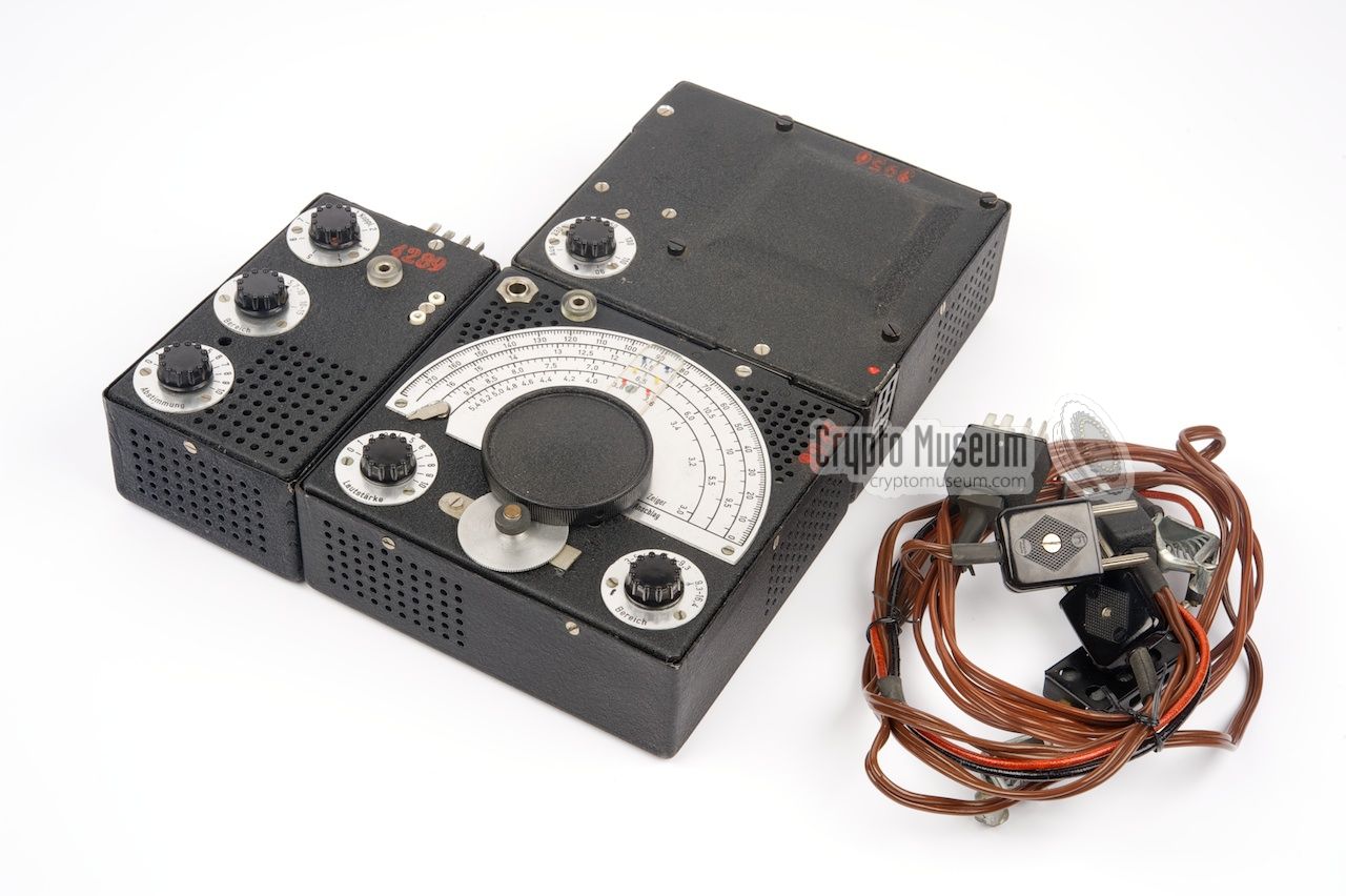
- 4-piece version
This version consisted of the four units listed below, interconnected via
Jones plugs and sockets that are integrated in the sides of the units.
Due to the smaller size of the individual modules, this version is easier
to conceal. Most of the surviving 12WG sets are of this type.
- 2-piece version
The version is electrically identical, but consists of only two modules:
a combined receiver/transmitter and a combined PSU with metering unit.
The two modules are interconnected via Jones connectors. This variant was
less common than the 4-piece one.
|
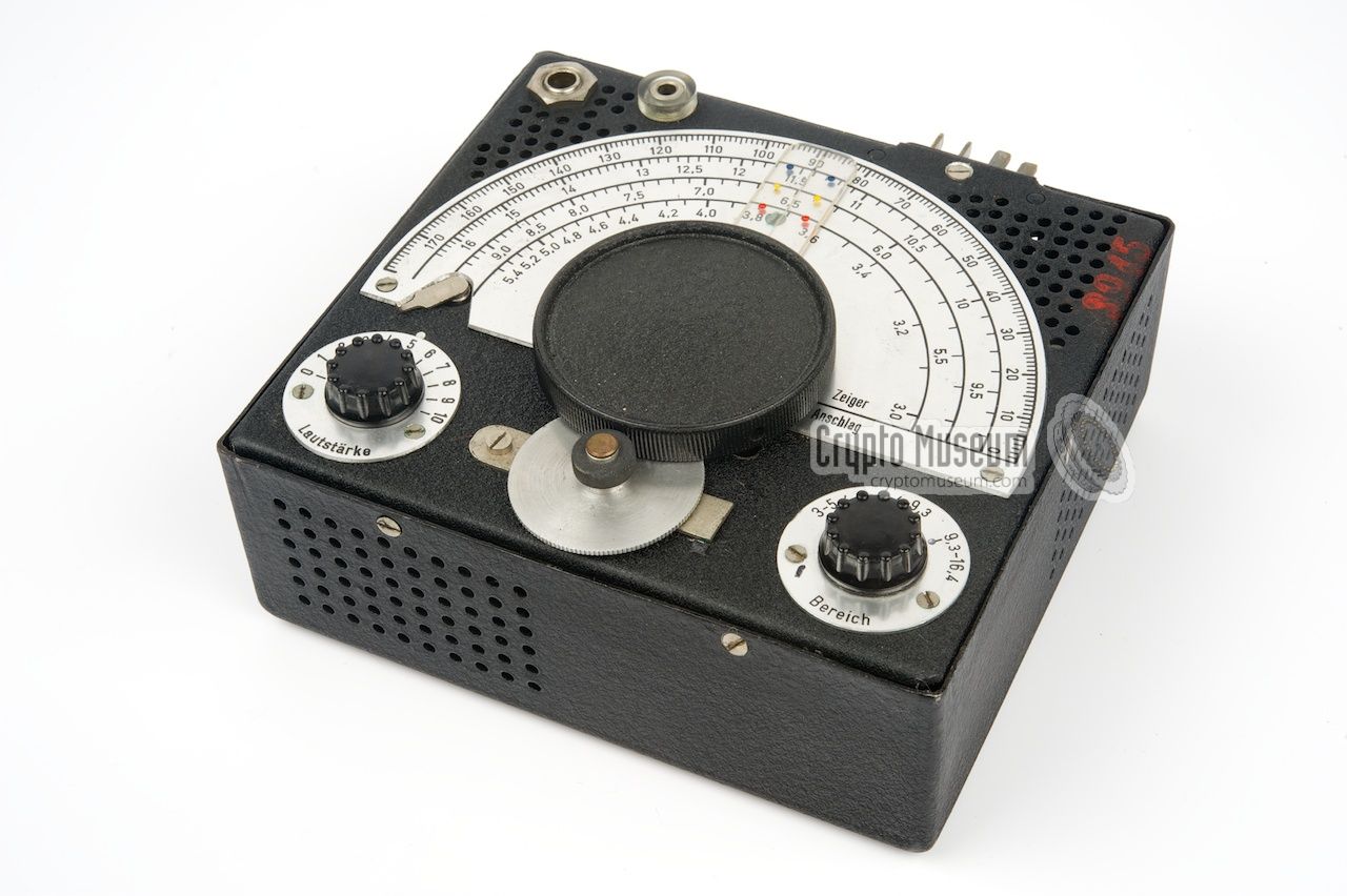
The diagram below shows the various features of the receiver. The 3 - 16.4 MHz
frequency range is divided over 3 bands that can be selected with the rotary
switch at the bottom right. The large frequency scale allows accurate tuning
and has an additional fine-tuning knob at the bottom edge. The dial has three
scales, one for each frequency band, plus a 4th linear scale. The unit should
be plugged into the PSU. Antenna and a headphones are
connected at the top left.
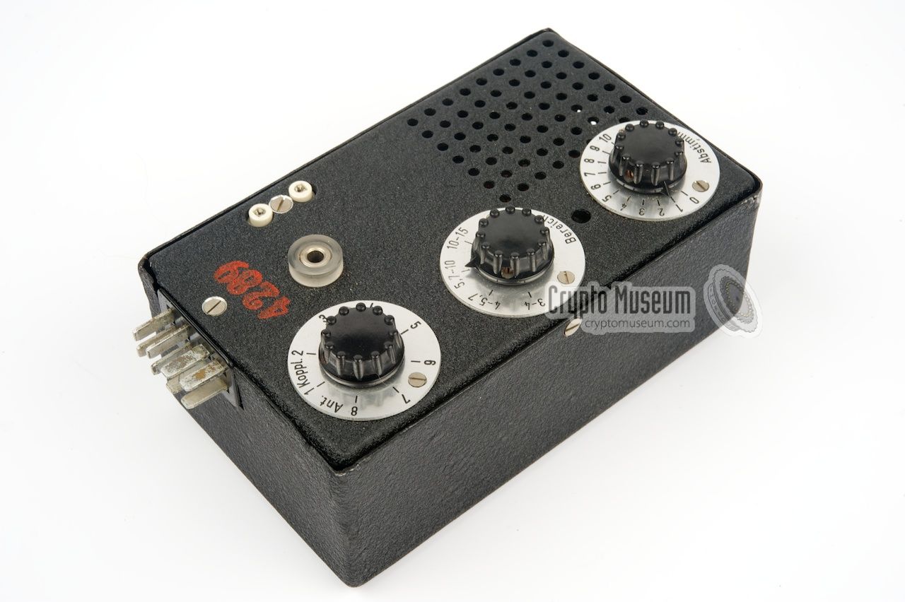
The transmitter is about half the size of the receiver and is shown in the
diagram below. It should be connected to the Metering Unit, which in turn is
connected to the PSU. A suitable crystal for the desired frequency should be
placed on the socket at the right and a wire antenna must be connected to
the banana-type socket. Counterpoise must be connected to the Metering Unit,
just like the morse key. After tuning the oscillator and the antenna, the
transmitter is ready for use.
The diagram below shows the 12WG/N power supply unit (PSU). It is the central
piece of the radio set and connects to the AC or DC power source, the receiver
and the metering unit (which in turn is connected to the transmitter). The
PSU can only be used together with the metering unit, as the latter contains
parts of the PSU circuitry that could not be fitted inside the PSU's enclosure.
|
The receiver is probably the most sophisticated part of the 12WG set.
It measures 15 x 13.5 x 5.5 cm and has the same form factor as the PSU.
It can be tuned to any frequency in the 3 to 16.4 MHz range, divided over
3 colour-coded bands.
The big knob at the center is the frequency adjustement, which can be fine
tuned with the aluminium wheel at the south edge. The knob at the left is
for adjusting the volume. A small lever, just above the volume control, is
for adjusting the amount of feedback. It should be tuned for maximum noise
level.
|
|
|
The transmitter is housed in one of the smaller enclosures. It measures
8 x 13.5 x 5.5 cm and is built around a single valve. It is crystal-operated
and is suitable for frequencies between 3 and 15 MHz, divided over 4 bands.
Apart from the band selector, it has knobs for adjusting the crystal oscillator
and for tuning the antenna, both of which should be used in combination with
the separate 12WG/M Metering Unit.
A suitable wire antenna should be connected to the banana socket on top of
the unit.
|
|
|
The PSU is a vital part of the 12WG, at it provides the HT and LT voltages
for the receiver and the transmitter. It measures 15 x 13.5 x 5.5 cm and is
the heavyest module of the set. It contains the transformer, for AC use,
and a vibrator pack, which is used when powering the set from a 6V DC source
such as the battery of a motorcycle.
The PSU has three sockets: one for the metering unit (west side), one
for the receiver (south side) and one for the power cable. The latter is
located at the east side of the unit and is marked with a red dot.
Cable wiring is specified below.
|
|
|
The small module that sits at the top left of the complete radio set,
is the so-called metering unit. As the name suggests, it contains a meter
and a rotary switch to select what you want to check: the Anode voltage (HT),
the 6.3V filament voltage (LT) or the antenna current.
The metering unit is connected to the PSU and the transmitter, and handles
the power, antenna and morse key lines to the transmitter.
Unfortunately, the metering unit is missing from the set in our collection.
|
|
|
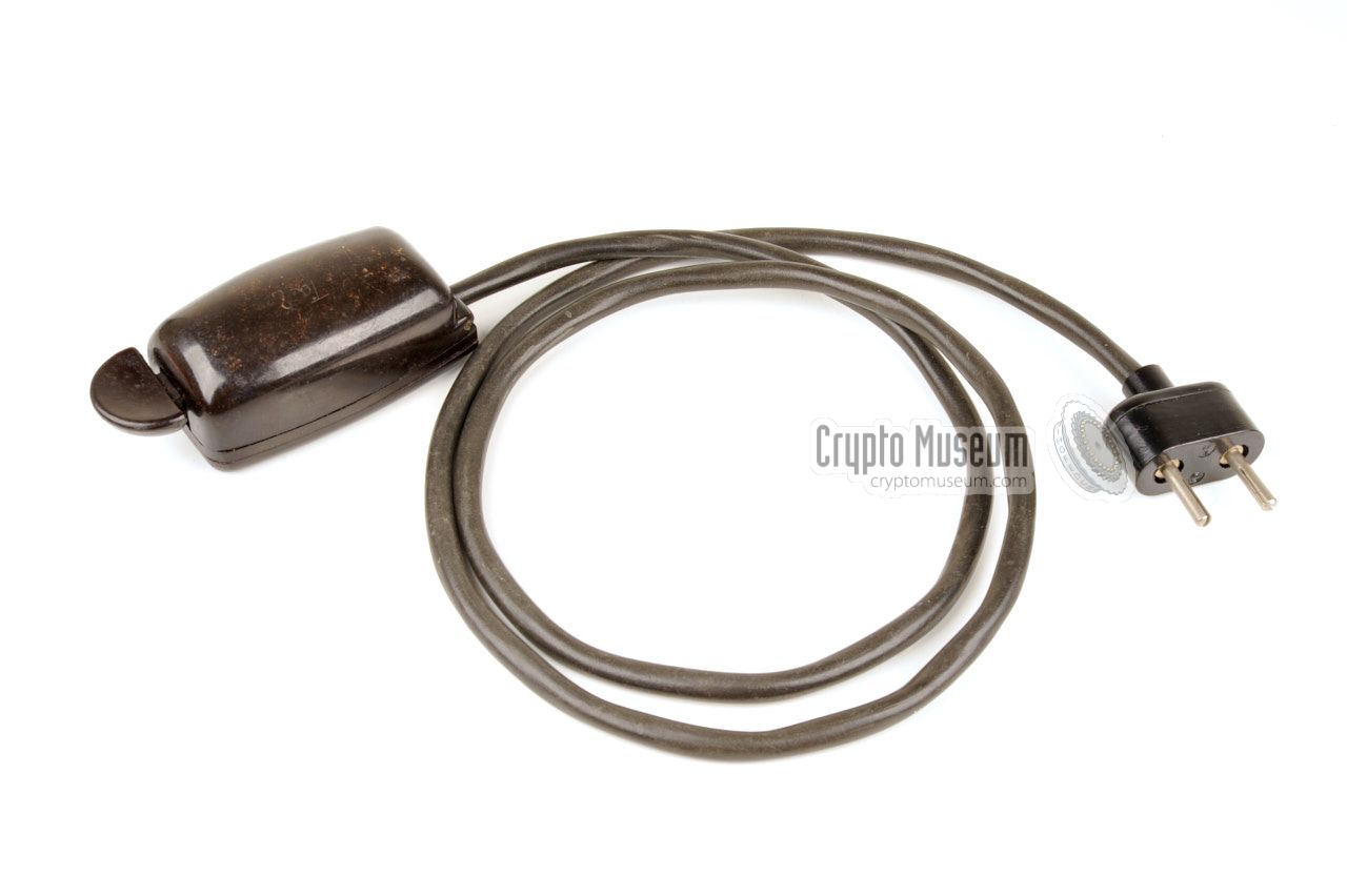
Surviving 12WG radio sets have been found with a variety of morse keys.
Although the 12WG did not come with a purpose built morse key,
it was commonly supplied with a wartime 'leftover', such as the
Ta.P. Wehrmacht key shown here.
This key came with a 1 metre long rubber cable with a 2-pin plug at the end.
This standard Wehrmacht plug has a pin distance of 19 mm and directly
fits the morse key socket of the 12WG/M unit.
|
|
|
|
Another example of a morse key that was frequently issued with the 12WG,
is the TKP or Maus (mouse). It came in two variants: with a circular
knob and with a half-moon knob. They were typically issued with
spy radio sets during the war, but were more difficult to operate
than the Ta.P. Wehrmacht keys.
|
|
|
The 12WG can be powered directly from the AC mains, in virtually any place
or country in the world with a mains voltage between 90 and 230V, selectable
with a rotary selector on the PSU. The cable shown in the image on the right
was supplied with every 12WG unit as standard.
The cable is fitted with a Hirschmann 2-pin mains plug that fits most of
the mains wall sockets in continental Europe. For other countries, the power
plug had to be replaced by a local one. The wiring of the
AC mains cable
is available below.
|
|
|
Alternatively, the 12WG could be powered by a 6V DC source, such as the
battery of a car or a motorcycle. Especially for use in rural areas, in which
no mains AC network was available, the 12WG was often supplied with a
6V motorcycle battery, in which case the PSU was used as a power-inverter.
The cable shown on the right can be used to power the 12WG from a 6V DC source.
The wiring of this cable can be found below.
|
|
|
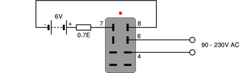
When the 12WG was issued with a 6V DC motorcycle battery, the battery
had to be recharged regualarly, which was generally done from an AC mains
wall socket using the cable shown in the image on the right.
The cable connects to the AC wall socket as well as to the battery, which
is then charged. Note the 0.7Ω current-limiting resistor in the (+) line.
The wiring of the charge cable is given below.
|
|
|
|
Each of the four (or two) units of the 12WG consists of a front panel -
to which all components are mounted - and an enclosure in the form of
a black metal case shell that is affixed to the sides of the front panel.
The case shell has ventilation holes and can easily be separated after
removing the screws around the edges of the front panel.
Note that the case shells may bind somewhat.
|
WARNING — in the section below, the interior of each of the four units
and their circuit diagrams are discussed in more detail. Note that these
circuit diagrams have been recreated by ourselves, as the original ones
contain too many mistakes. The same is true for the pinout of the 8-pin
Jones sockets that are used for connection between the units.
Do not trust the original circuit diagram when repairing an original
12WG radio set.
|
The interior of the PSU can be accessed by removing 4 screws, one at each side
of the case, and then removing the case shell. This may take some effort, especially
if the PSU has never been opened before. Please note that the PSU can not be
used by itself, as it is not a standalone unit.
|
All components are mounted to the front panel, which is made of 2 mm thick
aluminium. The PSU has three 8-pin female Jones-type sockets at its sides,
one for the power source, one for the receiver and one for the metering unit.
Inside the PSU is a large transformer, a vibrator unit,
the mains voltage selector, a large selenium diode (the red square at the front)
and several
smaller components. The image on the right shows the interior of the PSU,
which is upside down, shown from the corner of the voltage selector.
At the front left is the receiver socket.
|
|
|
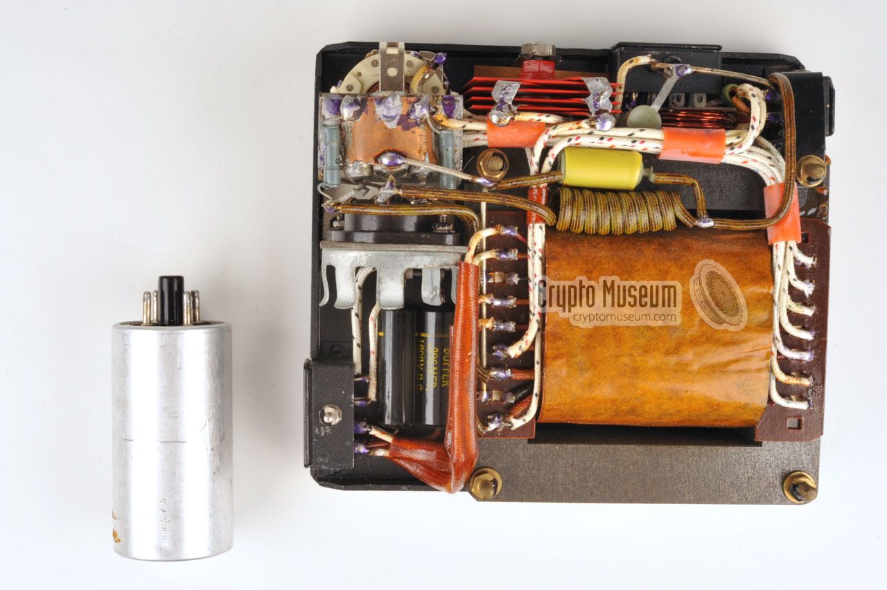
The aluminium cylindrical can at the top right, is the vibrator unit, which is
used to convert the 6V DC voltage from an external battery into AC, which can then
be used to drive the transformer. The vibrator runs at 115 Hz and is mounted in a
socket, so that it can easily be replaced in case of a defect.
Note that the 6X4 rectifying valve, which is part of the PSU circuit, is not
mounted inside the PSU itself but in the metering unit,
probably due to lack of space.
|
|
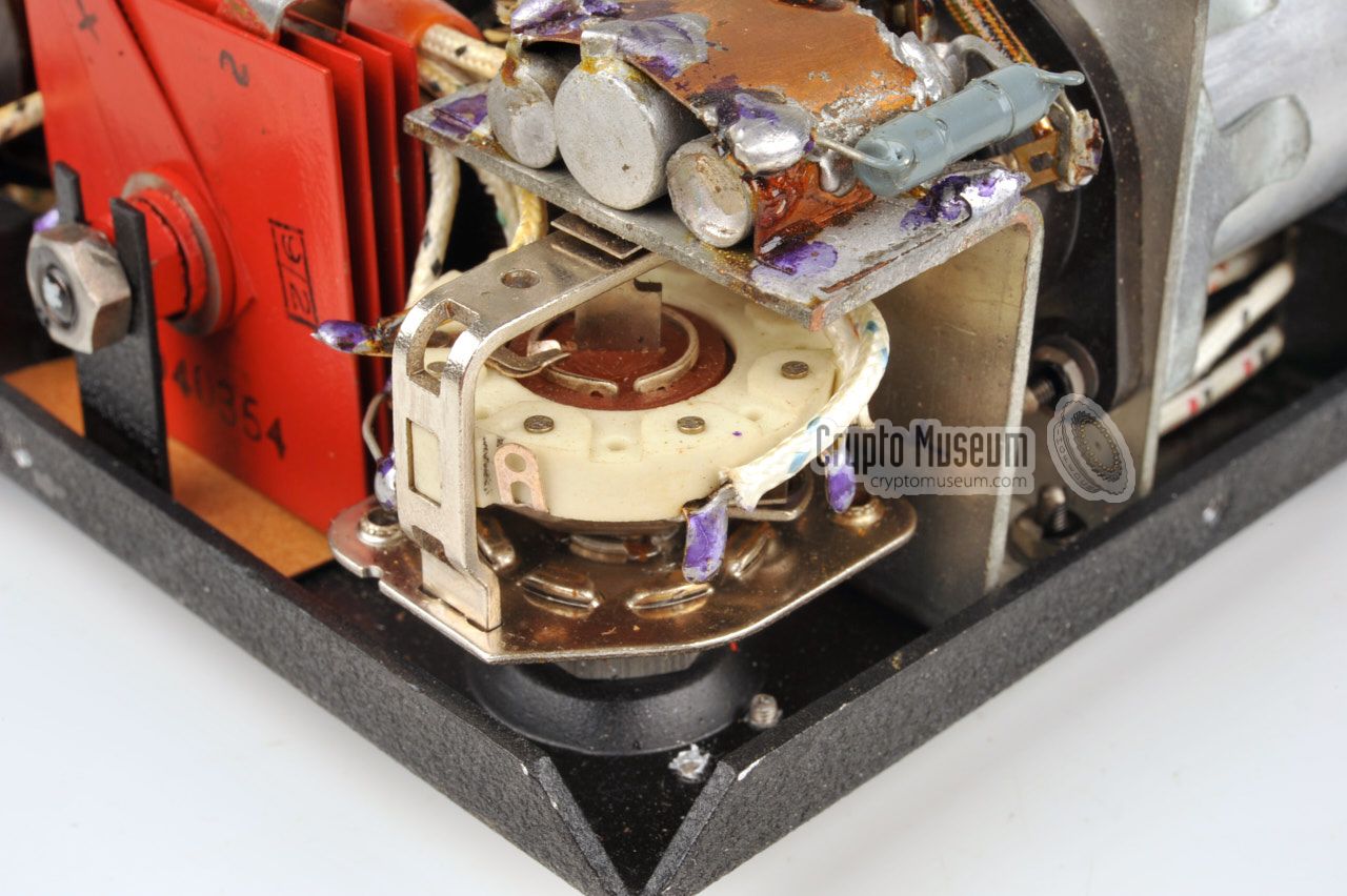
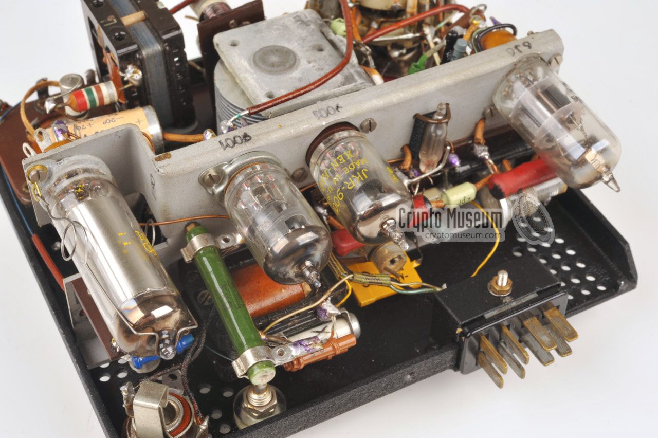
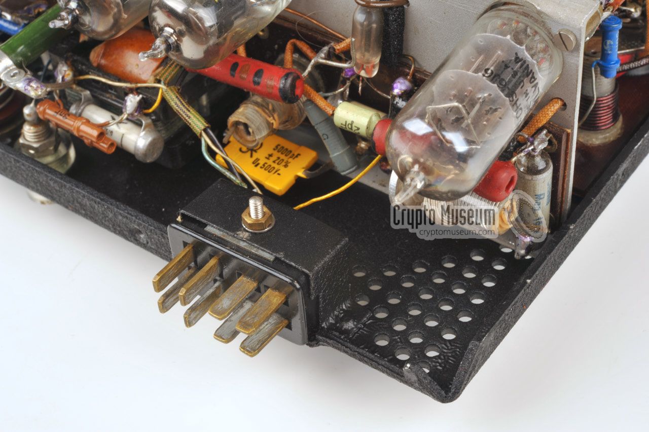
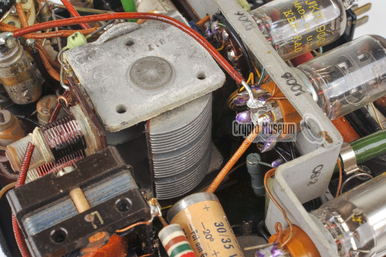
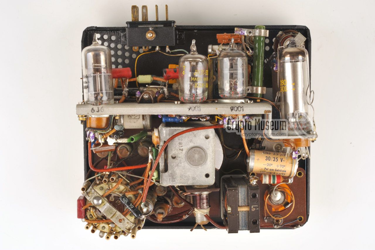
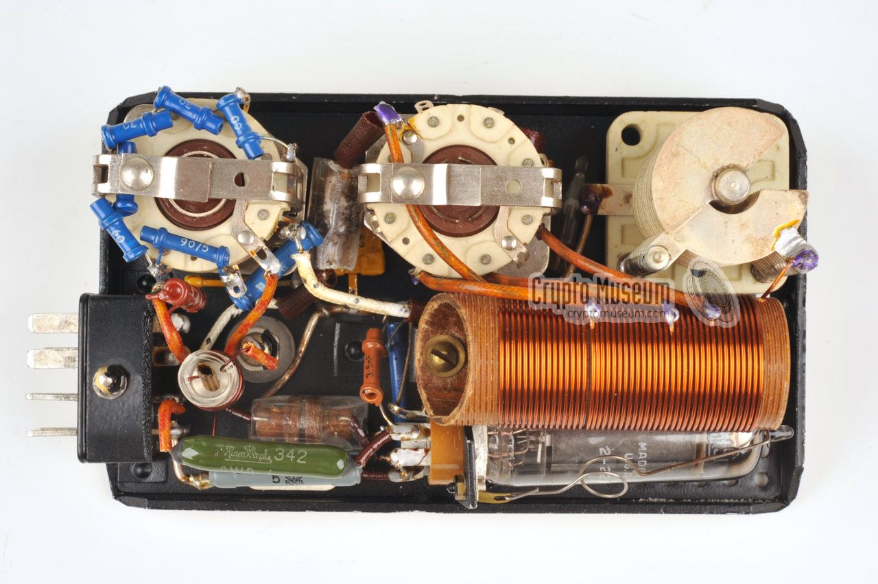
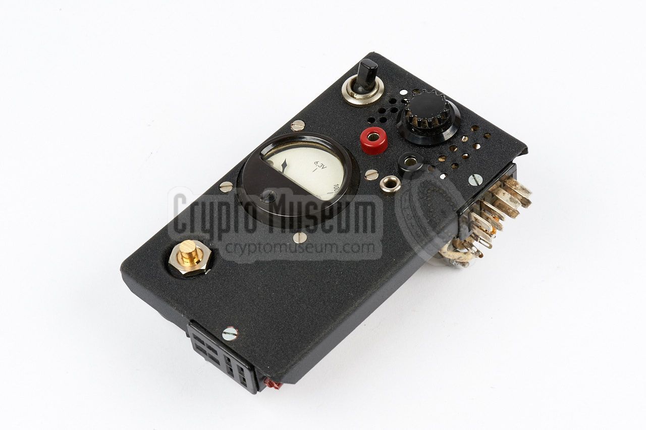
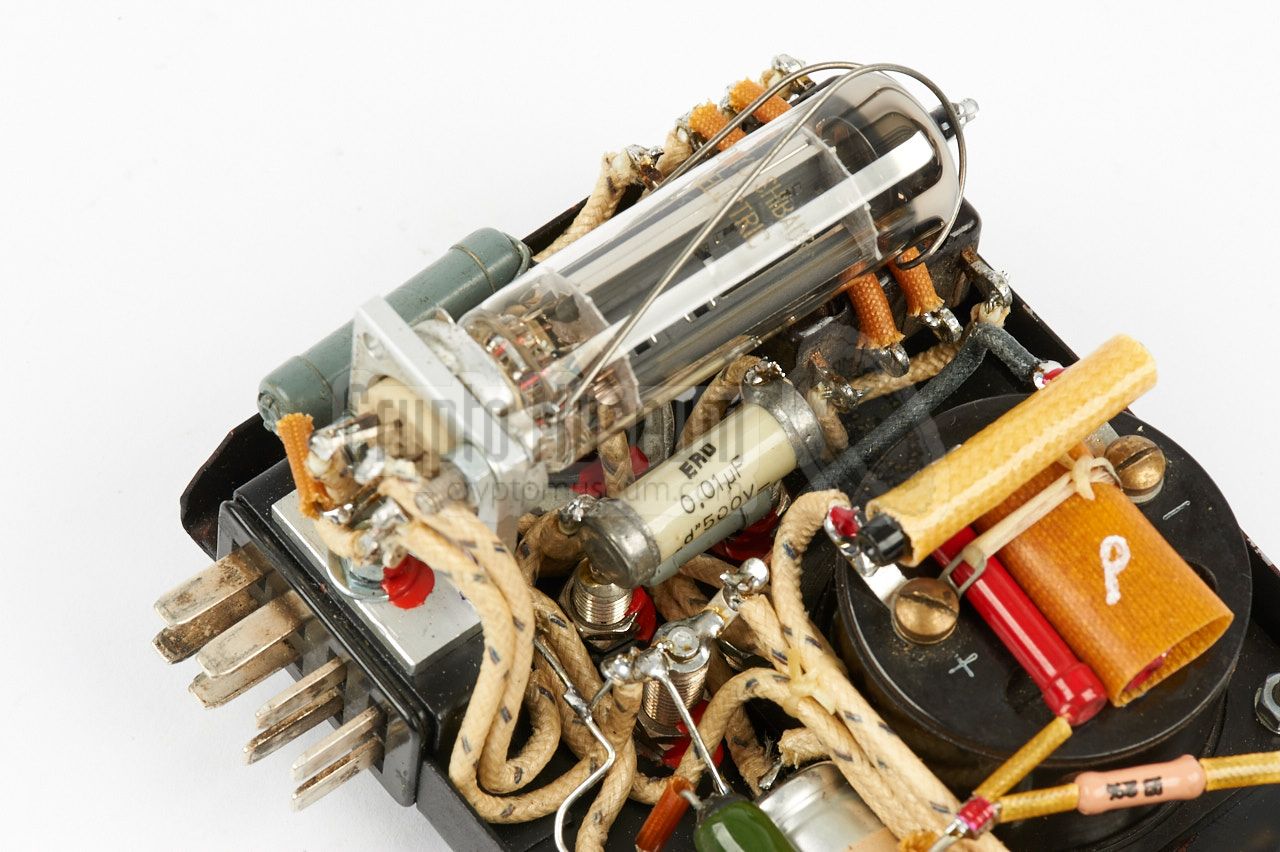
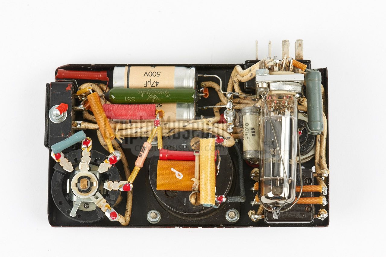
The metering unit is a rather strange unit, which connects the transmitter
to the PSU. It is used for checking the voltages and the antenna current, but
also contains the PSU's rectifier valve, which could not be fitted inside the
PSU itself. The unit also holds the socket for the morse key.
|
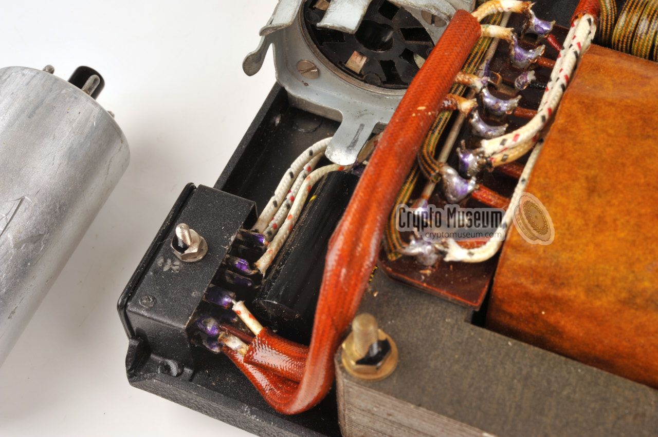
The interior of the metering unit can be accessed by removing just three screws
from the sides of the unit, after which the case shell can be removed.
Please note that the metering unit is missing from the 12WG set in our collection,
so we have to rely on images that were kindly provided by
Nico van Dongen,
who has the unit but without the original enclosure [5].
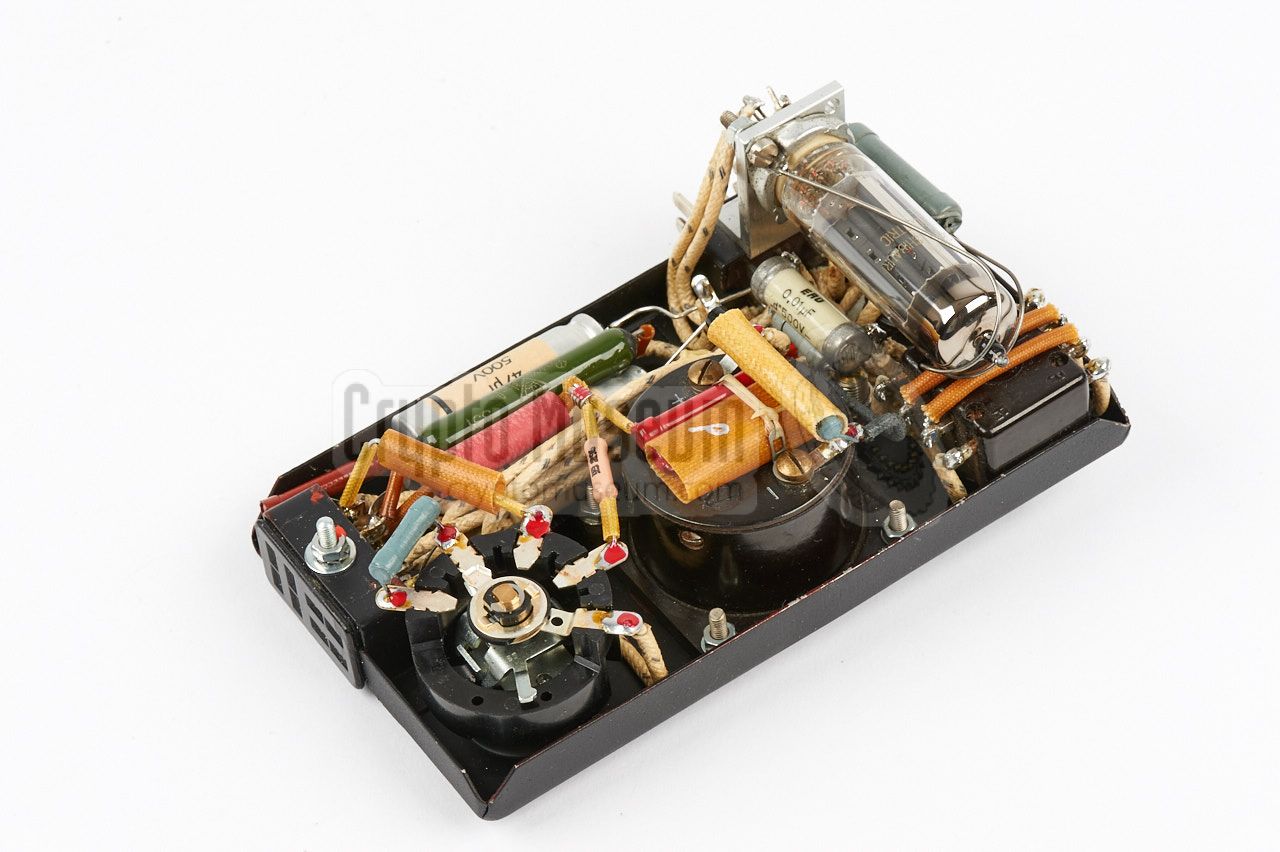
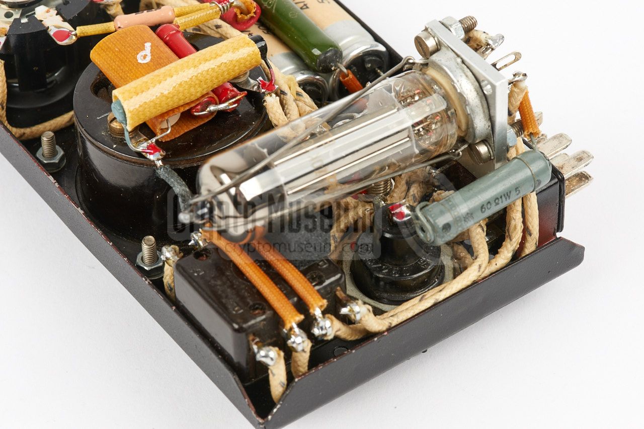
The image on the right shows the interior of the metering unit as seen from
the bottom, with the 6X4 rectifier valve at the top (here at the left). The valve
is mounted on an aluminium bracket, and is located below the fuse holder
and the pre-heat switch.
|
|
|
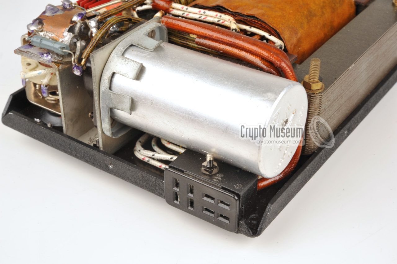
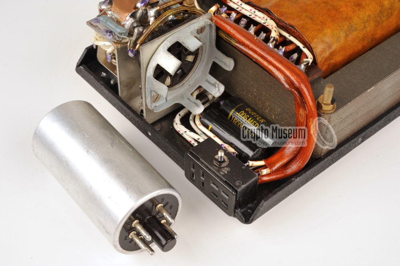
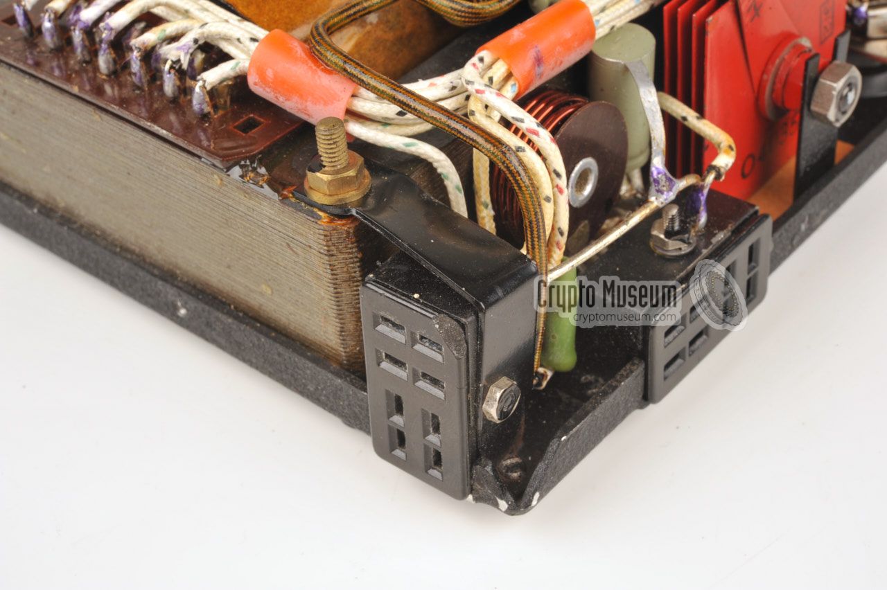
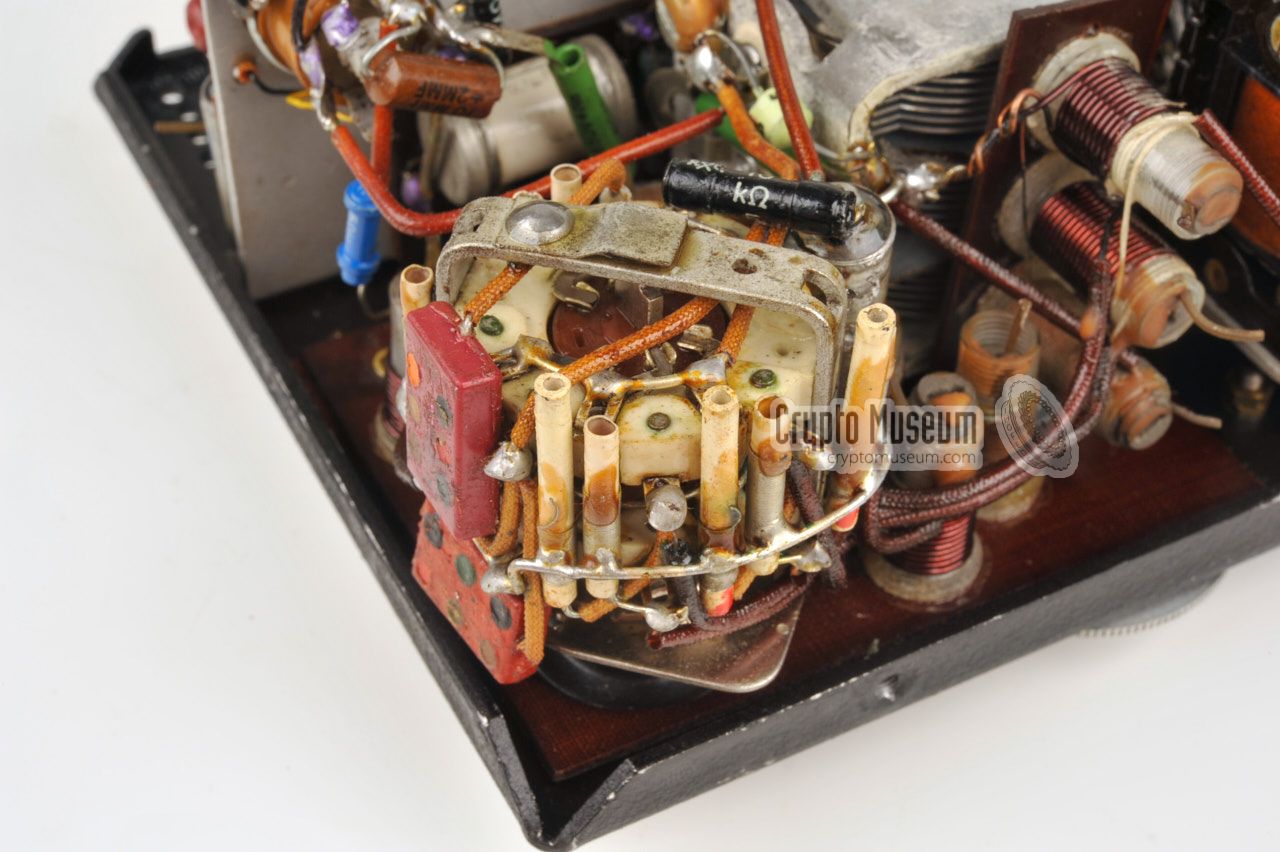
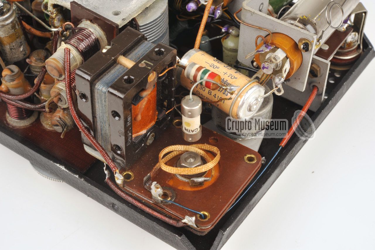
Note that some capacitors have been replaced and that the reproduction
enclosure is made of PCB material. All other parts are original.
As the metering unit was completely missing from our 12-WG unit, which
appears to be rather common, we had to extract it from the full circuit
diagram, in order to build a replica of it. The diagram with the correct
pinout of the two Jones connectors is shown below. The layout of both
Jones connectors is given further down this page.
|
|
The interior of the receiver can be accessed by removing five screws from
the sides of the case and removing the case shell. This may take some
effort, especially if the unit has never been opened before. The best
approach would be to lift the front panel at the Jones connector end.
|
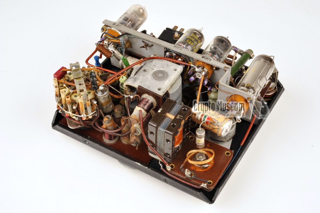
The image on the right shows the interior of the receiver after the case
shell has been removed. All components are mounted to the front panel,
including an aluminium sub-frame that hold the four valves and several other
components.
The receiver is a superheterodyne, consisting of a mixer, oscillator, IF
stage with regeneration, detector and AF amplifier. It is suitable for the
reception of AM and CW signals. The receiver is connected to the power
supply unit via an 8-pin Jones connector, of which only 4 wires are used.
Power (HT and LT) is supplied via this connector.
|
|
|
The connector also provides the receiver with a sidetone signal
from the transmitter, so that the operator can hear his own morse when
transmitting, regardless of the receive frequency. Headphones and
antenna should be connected at the receiver's front panel.
Ground is connected to the metering unit. The full circuit diagram of
the receiver is given below. Note that it differs from the original
diagram that was supplied with each unit, as the latter contains
quite a few mistakes.
|
|
The interior of the transmitter can be accessed by removing just three screws
from the sides of the unit, and then removing the case shell. This may take some
effort, especially if the case has never been opened before. The transmitter
is only connected to the Metering Unit, from which it receives the power and
which holds the socket for the morse key and the antenna current meter.
|
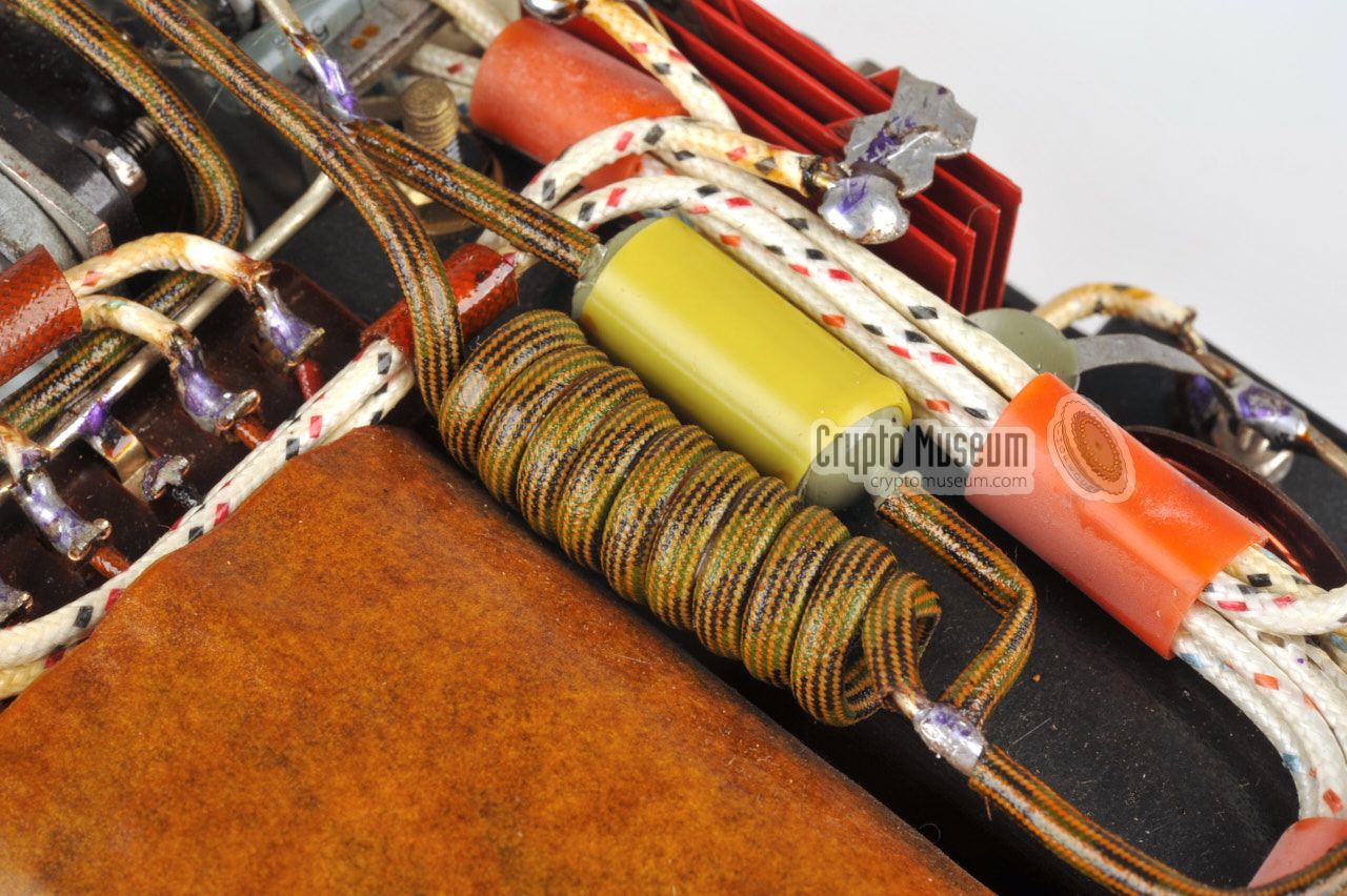
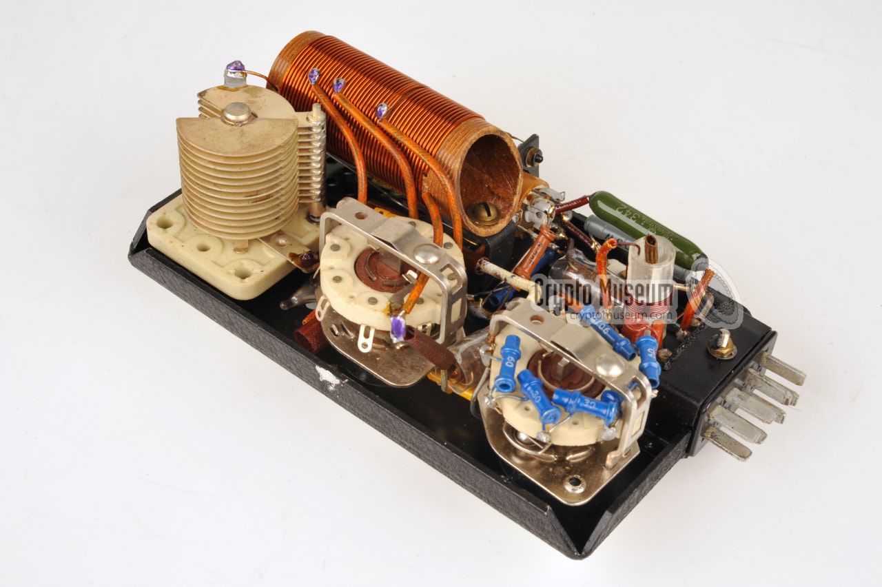
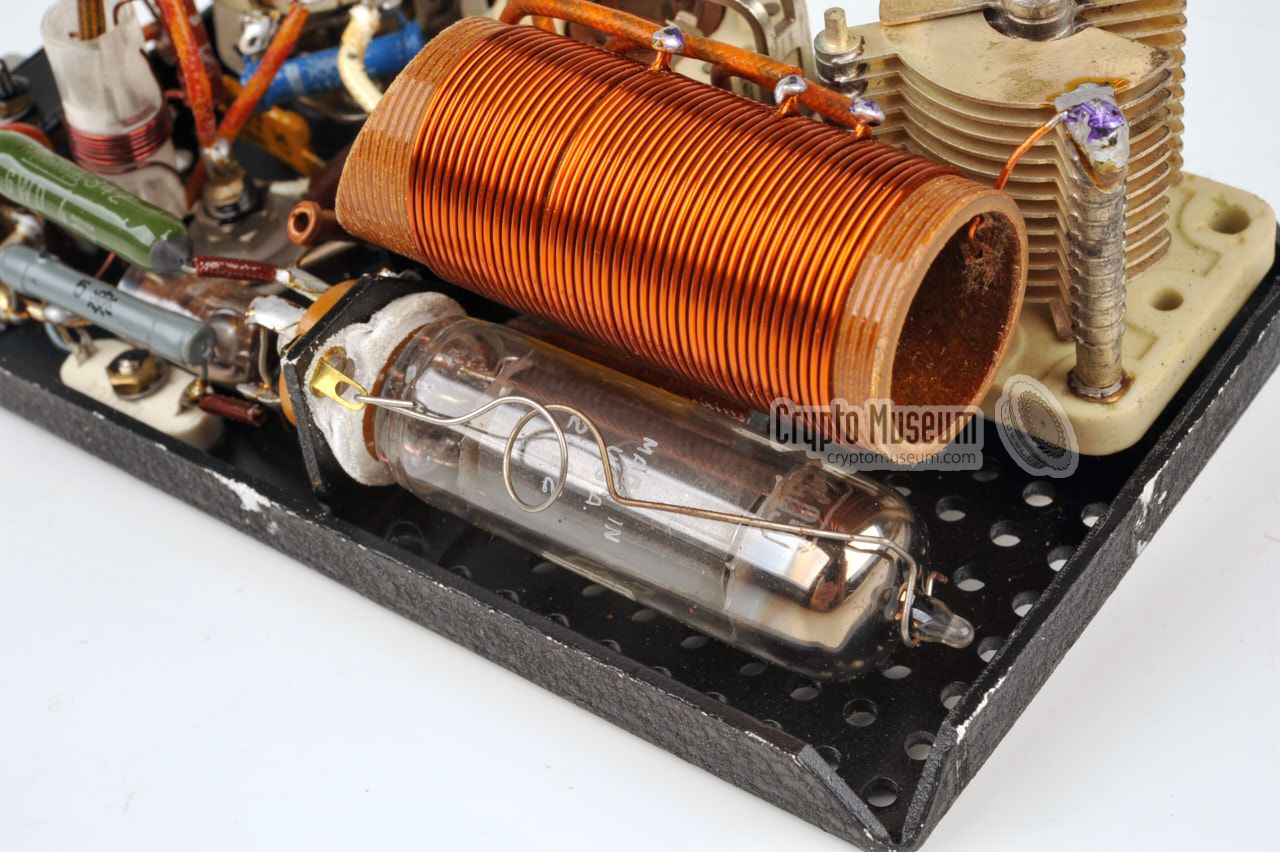
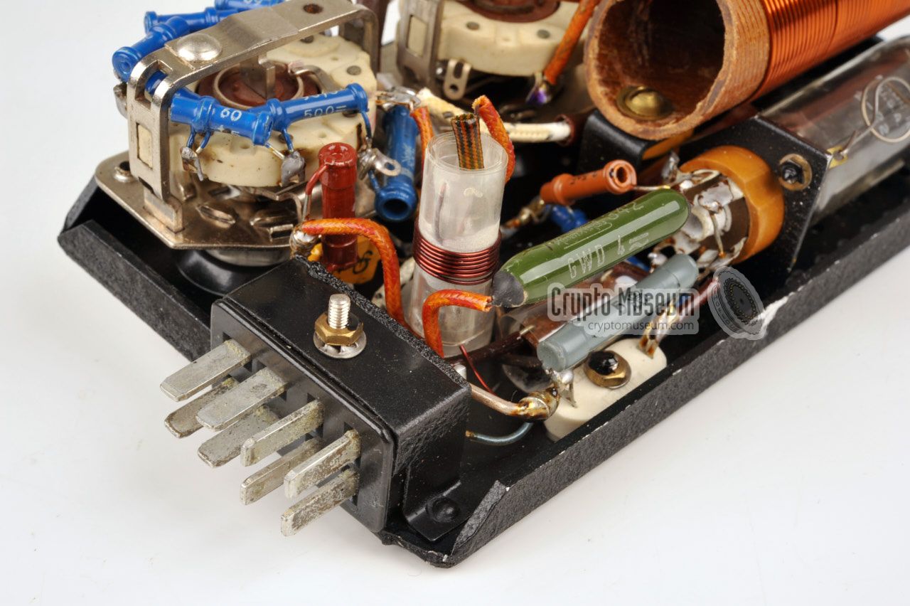
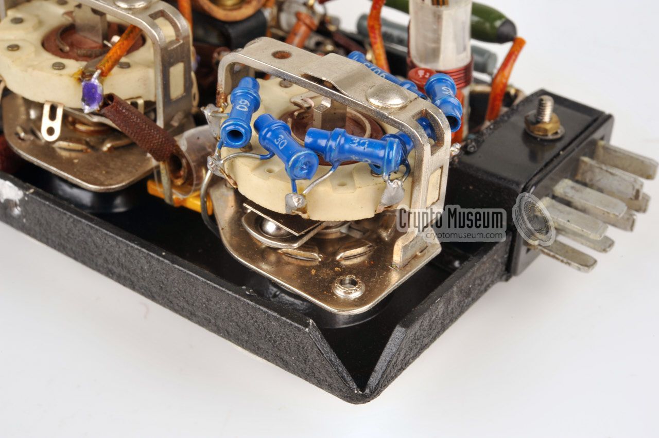
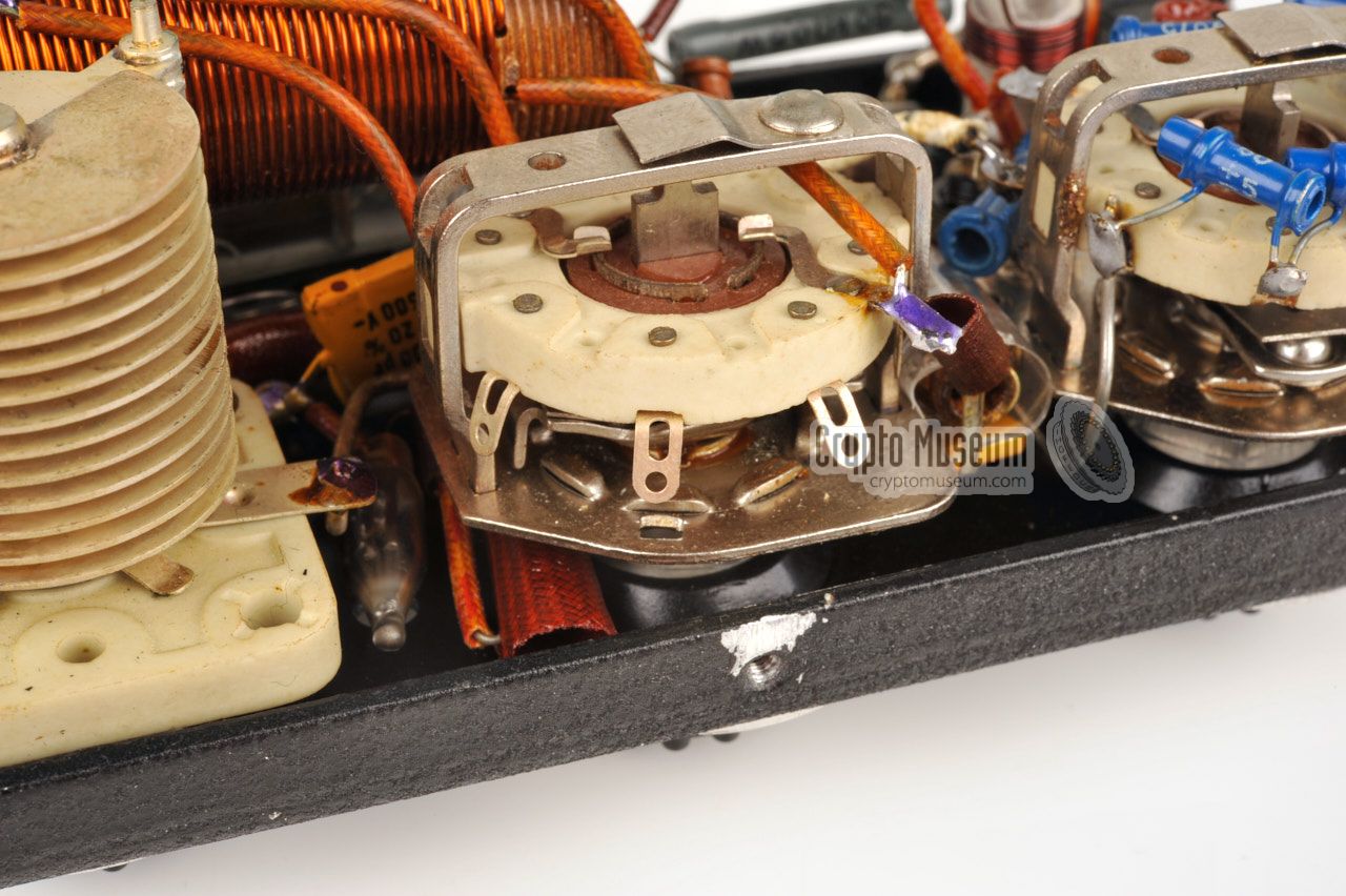
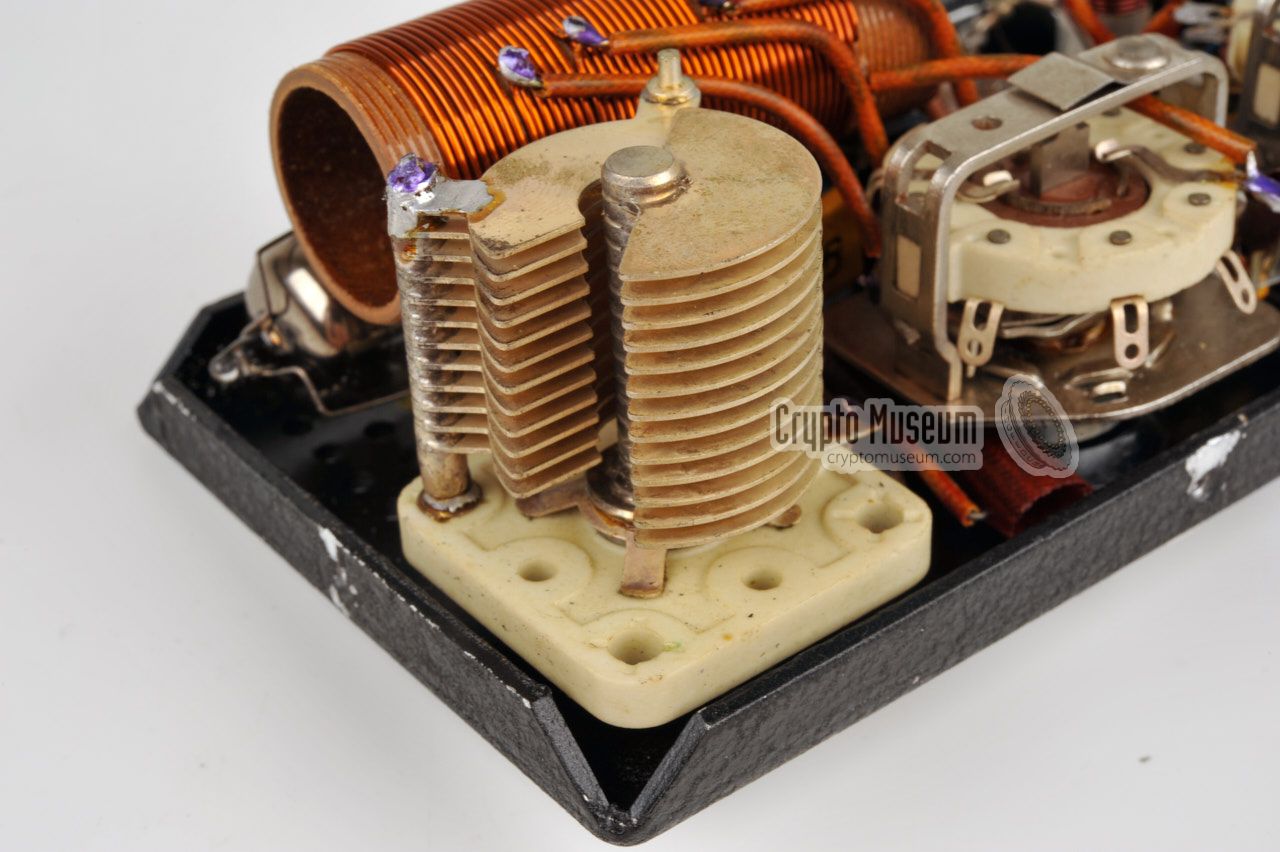
The transmitter circuit inside the 12WG/S
is very simple and consists of a single 6AQ5 valve,
a large coil with several taps, a tuning capacitor, a crystal (socket) and
a few passive components.
The image on the right shows a bottom view of the transmitter, seen from the
south-east corner. At the front is the
6AQ5 transmitter valve, with the large
coild just behind it. The crystal socket is visible close to the edge,
just left of the valve socket.
|
|
|
|
Most of the surviving 12WG radio sets, were released through official government
surplus sales in Germany during the 1970s and 80s. Unfortunatly, the metering
unit is often missing from these sets, probably as it was thought to be
the transmitter. As the laws of the 1970s did not allow a person to possess a
transmitter without a proper licence, they were ordered to be destroyed.
|
The same is true for the 12WG in our collection, that came as a three-part
set. Luckily complete sets were available in some museums, such as the
Technisches Museum in München (Germany).
Furthermore, Dutch collector Nico
van Dongen [5] has a complete set, albeit without the original enclosures.
From photographs supplied by him and others, we were able to reconstruct
the metering unit. In a joint effort with Austrian collector Günter Hütter [6],
who also owns an incomplete 12WG set, we were able to recreate an operational
authentic metering unit.
|
|
|
|
IMPORTANT —
The various modules are interconnected by means of 8-pin Jones connectors,
which were very common in the era in which the 12WG radio set was developed,
and which can still be obtained relatively easy today. Note that the power
cable has a female Jones plug at one end, which can be VERY DANGEROUS
when touching the pins whilst the other end is plugged into the mains wall
socket. Furthermore, this cable should ONLY be plugged into the PSU socket
that is marked with a red dot.
Always connect the four units together and insert the mains cable into the red
market socket, before connecting the radio set to the mains.
|
The diagram below shows the pinout of the power input socket at the right
side of the Power Supply Unit (PSU), when looking into the socket. Note
that the red dot on top of the PSU, marks the top side of the socket.
When powering a 12WG, check out the cable wiring diagrams below.
|
- 0V DC in
- 6V DC in (from battery or vibrator)
- 6.3V out (from vibrator)
- Mains AC in
- +6V in (from battery)
- Mains AC in
- +6V out (to battery)
- 0V out (to battery)
|
|
|
The diagram below shows the pinout of the female socket on the 12WG/M
metering unit into which the transmitter should be plugged, when looking
into the socket. This is the same layout as on the soldering side of the
female connector at the north side of the transmitter itself.
|
- 0 V (ground)
- 6.3 V
- 400 V
- 400 V
- Morse key
- -
- Antenna current
- Antenna current
|
|
|
The diagram below shows the pinout of the female receiver socket on the PSU,
when looking into the socket. This layout is identical to the solder side
of the female connector at the north side of the receiver itself.
Note that the original circuit diagram shown the wrong pinout of this socket.
|
- 0 V (ground)
- 6.3 V
- 215 V
- Sidetone
- -
- -
- -
|
|
|
*) Important: the pinout of the receiver connector shown here
is different from the one shown in the original circuit diagram.
The circuit diagram is wrong. The one shown here is correct.
|
|
The diagram below shows the pinout of the female socket on the PSU to which
the metering unit is connected, when looking into the socket of the PSU.
This layout is identical to the solder side of the male connector at the
east side of the metering unit.
|
- 0 V (ground)
- 6.3 V
- 215 V
- Sidetone
- Trafo D
- Trafo B
- Trafo C
- Trafo A
|
|
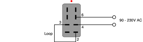
When connecting the PSU to the AC mains, use the wiring diagram below.
The PSU is suitable for AC mains voltages between 90 and 230V, but ensure
that voltage selector in the bottom left corner of the PSU is set to the
correct voltage before the PSU to the mains. Also ensure that the metering
unit is connected before powering the PSU, as it contains the rectifier valve.
Do not forget the loop wire between pins 2 and 3.
It is necessary to supply the 6.3V to the filaments.
|
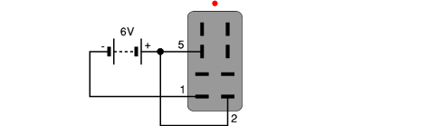
The 12WG can also be powered from a single 6V DC source, such as the battery
of a car or motorcycle, in which case the transformer is used, in combination
with an electromechanical vibrator, as a step-up converter. When powering
the 12WG from 6V DC, the cable should be wired as shown below. Do not forget
the loop wire for the filaments between pins 2 and 5.
|
The 12WG was sometimes supplied with a small motorcycle battery that
allowed the set to be operated in remote areas where no mains power
was available. In such cases it was necessary to recharge the battery
from time to time, which could be done with the existing PSU.
Especially for this purpose the cable below was supplied.
Note the 0.7 Ω power resistor in the (+) line.
|
Receiver 1 x 6J6, 2 x 9001, 1 x OB2 Transmitter 1 x 6AQ5 Metering Unit 1 x 6X4
|
Power Supply 15 x 13.5 x 5.5 cm Receiver 15 x 13.5 x 5.5 cm Transmitter 8 x 13.5 x 5.5 cm Metering Unit 8 x 13.5 x 5.5 cm
|
-
OG = Organisation Gehlen (Gehlen Organization) →
Wikipedia
-
Document kindly supplied by Jim Meyer [7].
|
- Detlev Vreisleben, Information about the 12-WG
Personal correspondence. August 2015.
- Bundesnachrichtendienst (BND), Vitrine 11, Typ 12 WG
Si 90/1219. 11 September 2006. Kindly supplied by [1].
- Militär Historisches Museum, Achtung Spione (Katalog)
ISBN 978-3-95498-209-7. Dresden, March 2016. p. 260-261.
- Louis Meulstee, 12 WG
Wireless for the Warrior - Volume 4, Supplement, Chapter 53-1.
Retrieved May 2016.
- Nico van Dongen, Photographs of 12WG/M Metering Unit interior
Obtained May 2016. Reproduced here by kind permission.
- Günter Hütter, Reconstruction of the 12WG/M enclosure
July 2016.
- Helmut 'Jim' Meyer, HS0ZHK, My way to Ham - Radio and beyond
Website QRZ.COM. Personal correspondence.
- Jan Bury, Operation Stonka. An Ultimate Deception Spy Game
Cryptologia, Volume 35, 2011, Issue 4.
|
|
|
|
Any links shown in red are currently unavailable.
If you like the information on this website, why not make a donation?
© Crypto Museum. Created: Wednesday 18 May 2016. Last changed: Friday, 16 December 2022 - 11:21 CET.
|
 |

|
|


![12WG/M Metering Unit. Photograph kindly supplied by Detlev Vreisleben [2].](img/12wg_m_full.jpg)


![Metering unit in reproduction case. Photograph kindly supplied by Nico van Dongen [4].](img/301778/044/thumbnail.jpg "image # 301778/044")
![12WG/M interior. Photograph kindly supplied by Nico van Dongen [4].](img/301778/040/thumbnail.jpg "image # 301778/040")
![12WG/M interior. Photograph kindly supplied by Nico van Dongen [4].](img/301778/041/thumbnail.jpg "image # 301778/041")
![12WG/M interior. Photograph kindly supplied by Nico van Dongen [4].](img/301778/042/thumbnail.jpg "image # 301778/042")
![12WG/M interior. Photograph kindly supplied by Nico van Dongen [4].](img/301778/043/thumbnail.jpg "image # 301778/043")
![Metering unit in reproduction case. Photograph kindly supplied by Nico van Dongen [4].](img/301778/044/full.jpg)
![Metering unit in reproduction case. Photograph kindly supplied by Nico van Dongen [4].](img/301778/039/full.jpg)
![12WG/M interior. Photograph kindly supplied by Nico van Dongen [4].](img/301778/040/full.jpg)
![12WG/M interior. Photograph kindly supplied by Nico van Dongen [4].](img/301778/042/full.jpg)
![12WG/M interior. Photograph kindly supplied by Nico van Dongen [4].](img/301778/043/full.jpg)


