|
|
|
|
|

|
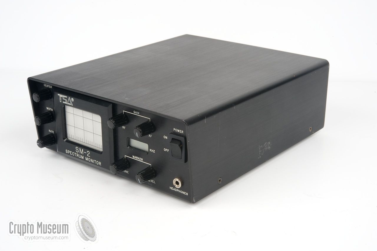
Spectrum Monitor
The SM-2 Spectrum Monitor (SM) was a panoramic viewer that was developed by
Glenn Whidden
of Technical Services Agency (TSA)
in the US in the mid-1980s,
as the successor to the SM-1.
It was an add-on to the Audiotel Scanlock Mark VB
and the Scanlock 2000 bug finders,
and allowed a small section of the frequency spectrum to be monitored
in real time, whilst searching for hidden radio transmitters (bugs).
In the UK, the SM-2 spectrum monitor was sold by Audiotel.
|
The unit can be connected to the 2MHz IF output that is available
on a mini BNC socket at the front panel of the
Scanlock. By making a
300 kHz section of the frequency spectrum visible, it becomes possible to
look for hidden or masked low power bugs that transmit at a frequency
very close to an existing strong broadcast station, or bug that use
a subcarrier for its modulation.
The first model was the Spectrum Monitor SM-1. It was introduced
in the late 1970s and sold for approx. US$ 2800. It was followed
a few years later by the improved SM-2 that is shown here.
|
|
|
The unit is about half the width of a Scanlock receiver and can easily
be placed on top of it.
It is powered by its internal 6V battery, or
from an external 12V DC source. When powered externally, the internal
battery is automatically charged. For connection to the Scanlock,
a special coax cable is needed,
with a normal BNC on one side and a mini-BNC at the other end.
The SM-1 and SM-2 appeared to be a very useful add-ons when finding
and identifying radio signals.
The monitor was available for many years and was even used with
the later Scanlock 2000 and the
Scanlock ECM, which features the same 2 MHz IF output.
In the UK, the spectrum monitors were sold by
Scanlock manufacturer Audiotel,
who marketed them as rebranded products.
|
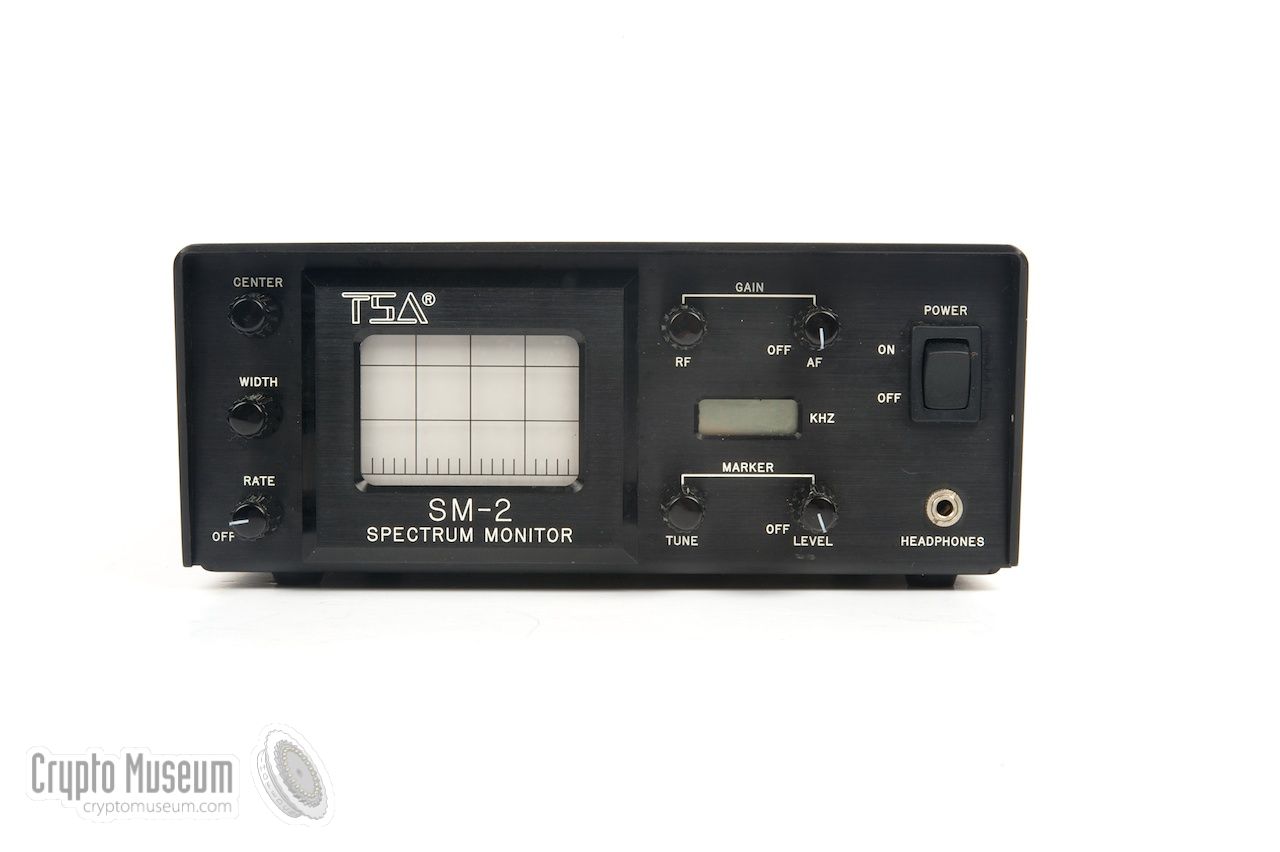
All controls of the SM-2 are at the front panel. After applying a 2MHz IF
signal from a Scanlock receiver and switching the unit ON with the power
switch at the top right, the green phosphor CRT screen should immediately
show a horizontal line with any radio signals displayed as a vertical
deviation of that line. When properly adjusted, the currently received
signal is shown at the center of the screen. The adjustments to the left
of the CRT can be used to alter the scanning speed (RATE) and the part
of the spectrum that is visible on the screen (WIDTH and CENTER).
At the right are the adjustment for the RF (input) level and the
AF (audio output) level for the headphones. The latter can be used to
listen to the signal produced by the video output stage and can be used
to identify certain signals acoustically. The small LCD screen can display
the IF frequency at the center of the screen. In order to use it properly
it has to be calibrated first, using the adjustments below it (MARKER).
This way it is possible, for example, to measure the distance (in kHz)
between a subcarrier and its audio or the distance between a
radio station and a bug.
|
|
The SM-2 is housed in a heavy black aluminium case that consists of
a bottom part with the front panel and the rear panel, plus a U-shaped
top panel that is held in place with four bolts at the sides. After
removing the four bolts, the top panel can be lifted upwards
and is then removed.
|
The interior consists of four PCBs (three large ones and a smaller
one), plus a small Cathode Ray Tube (CRT) that is used for displaying
the spectrum. Each PCB is mounted to the bottom of the case by means
of two supporting posts. The CRT is held in place with a mask at the front
and an aluminium bracket half way down its neck.
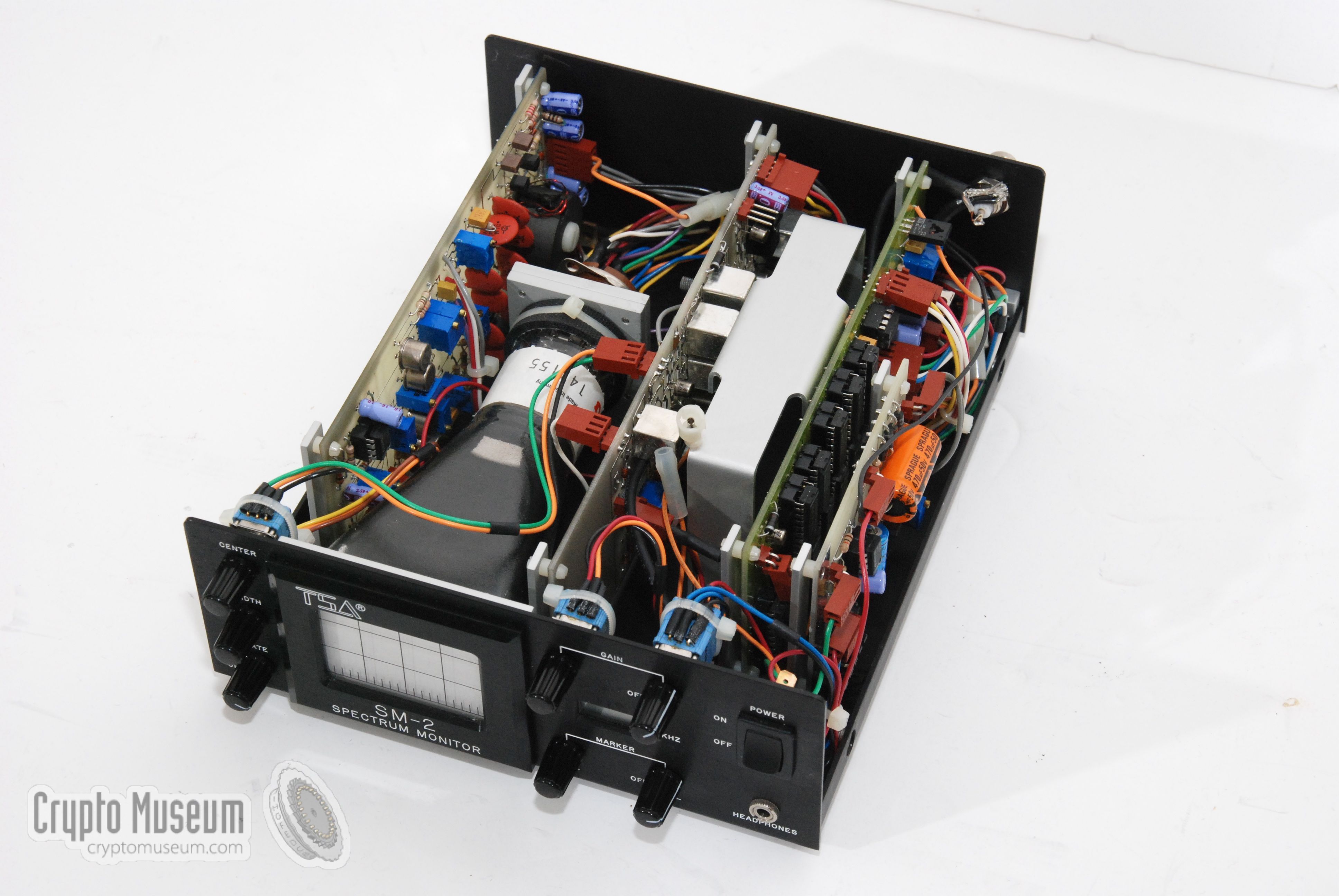
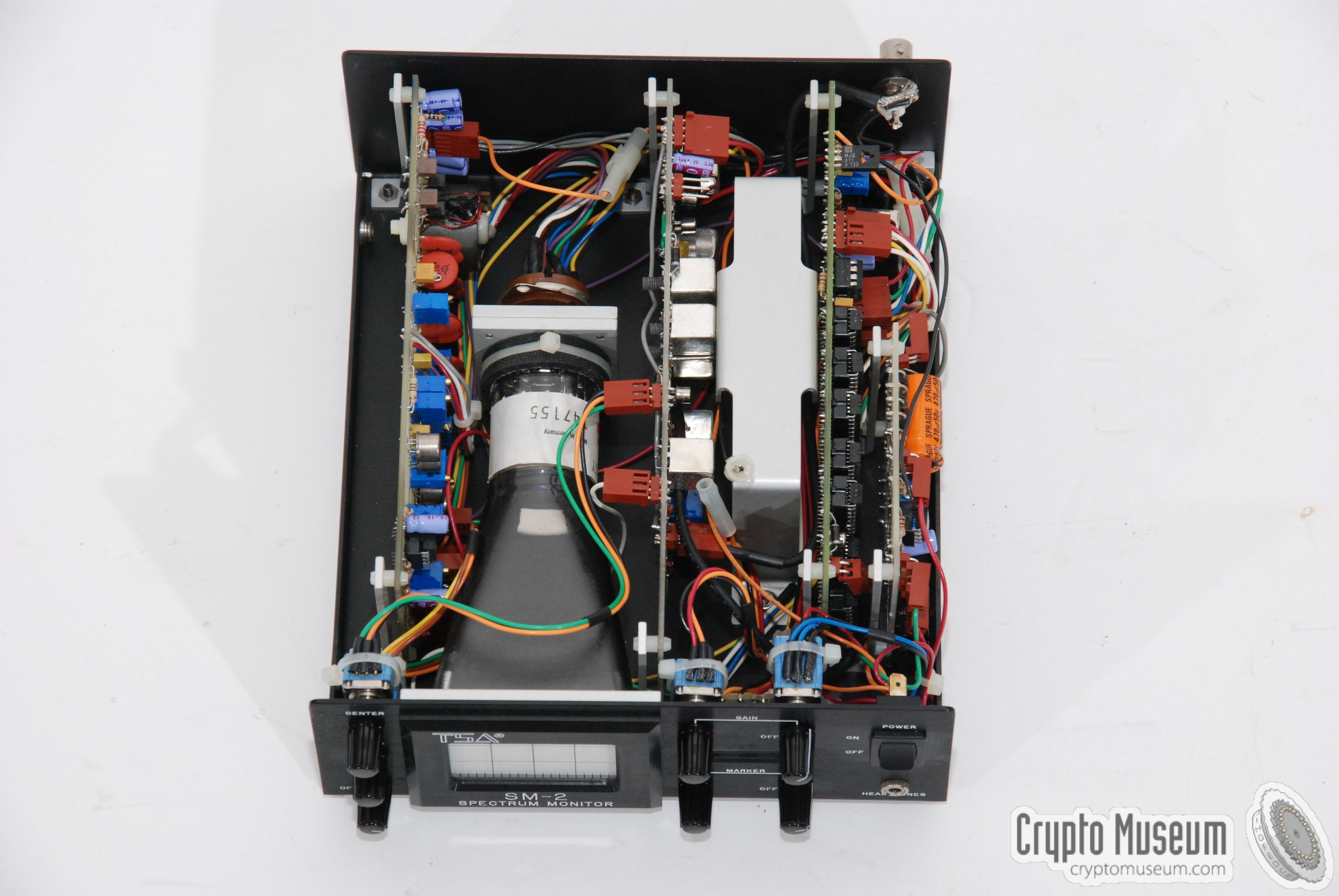
The image on the right shows the interior of the SM-2, seen from the
rear right. The image was taken whilst repairing the unit, which is why
the RF board at the center is lifted up and the CRT is not visible here.
The front panel is at the left.
|
|
|
Looking at the interior from the front,
we see from left to right:
the video board, the CRT, the RF board, the digital board and finally
the smaller audio board. All board are interconnected with individial
wires and a large number of connectors (18) some of which are hardly
reachable. A metal frame that holds the battery is mounted between
the RF board and the digital board. It is mounted in such a way that
it can easily cause a short circuit on both of the adjacent boards.
Looking at the boards, it seems obvious that the digital board was
added later and that it was designed by another person. It wasn't present
in the earlier SM-1 Spectrum Monitor and contains a frequency counter
that measure the frequency at the center of the screen (around 2 MHz).
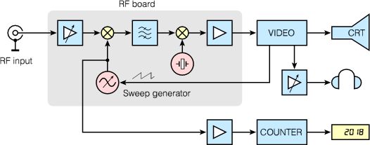
The block diagram above explains how the SM-2 works. At the heart of the
unit is the RF board that is located at the centre of the case. It
consists of a pre-amplifier with an adjustable gain (RF), followed
by the first mixer, where the signal is added to the signal of a varicap
controlled free-running oscillator (VCO. This generator is driven by
the horizontal deflection signal from the video board (saw-tooth).
After a 2nd mixer stage, the LF signal is amplified and used to drive
the vertical deflection of the CRT. The video signal is also fed into
an LF (audio) amplifier, to allow some level of (acoustical) identification
of the signal, using a pair of (external) headphones.
The signal from the sweep generator (VCO) is also used to drive
a digital counter that is mounted at the front panel. When the image
is properly centered on the screen, it displays the center frequency of
the RF signal (2 MHz). In the example above a frequency of 2018 kHz is shown.
|
|
The unit featured on this page, was added to our collection in 2009
after it had been in storage for over 10 years. When we first tried it
out, it appeared to be broken. The only thing that came to live was
the small LCD screen at the front panel, which was constantly showing
the number '0'.
|
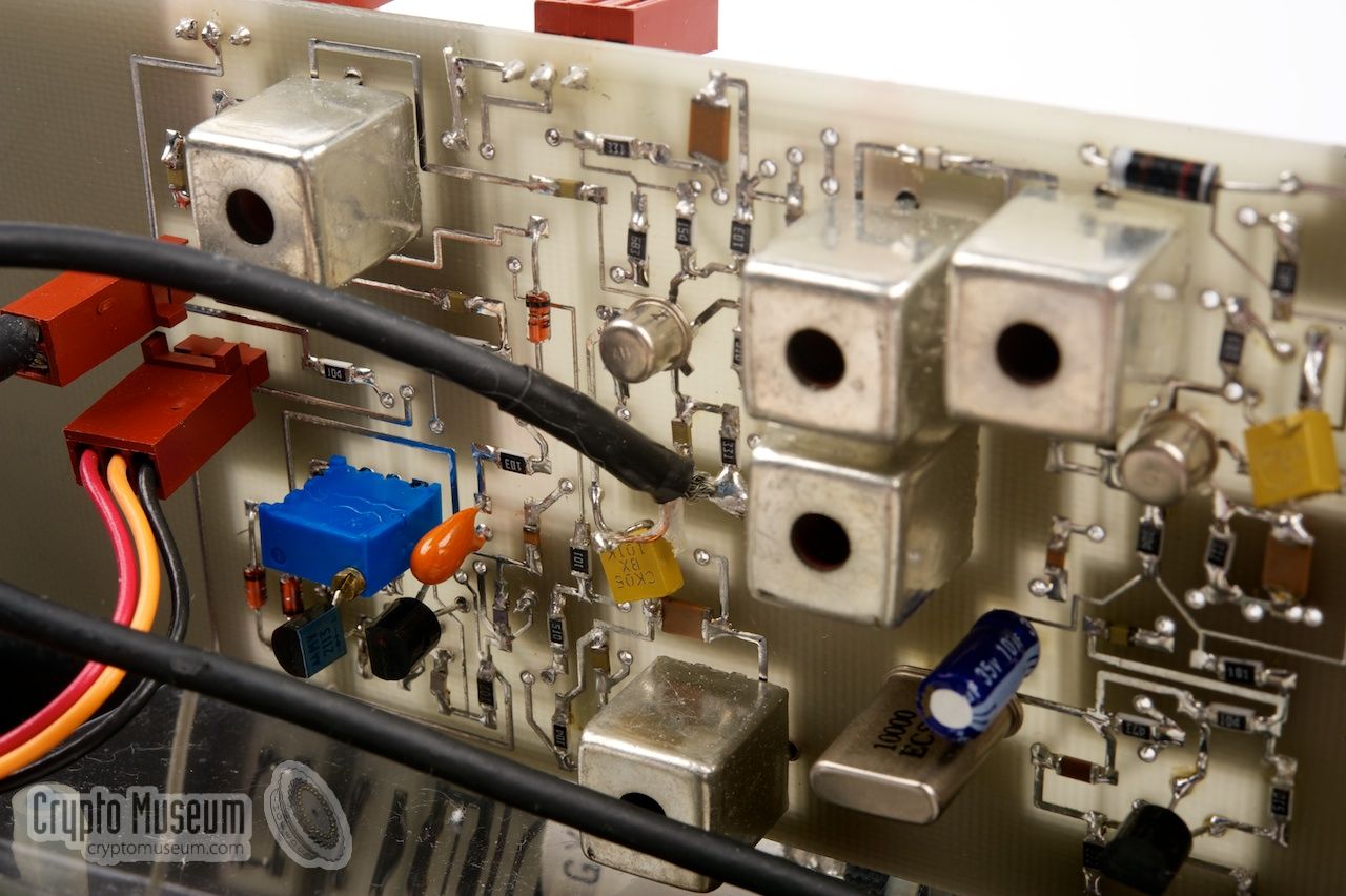
Although the interior of the unit
seemed clean and original, a close
inspection revealed that all of the small 10µF and 47µF capacitors on
all of the boards had been leaking,
causing damage to the PCBs
and disrupting normal functionality.
In case you ever come across a similar problem, just replace all these
low-quality electrolytical capacitors with proper ones,
clean the boards and restore all suspicious solder joints. On the
video board, the capacitors are close to the (thin) connections of the
HT transformer, so it might be necessary to resolder the wires of
that unit.
|
|
|
After the above was done, the video board came back to life and the
screen showed a green horizontal line at the bottom. Further investigation
showed that the sweep generator on the RF board wasn't working, so we had
to replace the 2N4903 and two of its resistors.
They had probably been damaged by a power surge via the horizontal
deflection line from the video board.
Once the RF board was repaired, the RF signal was
displayed nicely on the green CRT
and the RF level could be properly adjusted. The only thing
that was dead at this stage was the digital counter, which was still showing
a '0' on its display. It turned out that the only analogue component on this
board, the FET pre-amplifier at the input, was broken. After replacing the
RCA40673 MOSFET at the top left,
the counter worked fine again.
The image above shows the SM-2 in our workshop,
whilst reparing the RF board. The audio board is hanging out at the left.
|
|
|
|
Any links shown in red are currently unavailable.
If you like the information on this website, why not make a donation?
© Crypto Museum. Created: Wednesday 29 January 2014. Last changed: Saturday, 06 October 2018 - 14:29 CET.
|
 |

|
|
|