|
|
|
|
|

|
|
← EB-100 RX DF TSCM R&S EB-500 →
Portable monitoring receiver 10 kHz - 3 GHz
EB-200 Miniport is a high-end portable
monitoring and surveillance receiver,
developed around 1997 by Rohde & Schwarz
in München (Germany). Despite its small size, it covers a frequency
range from 10 kHz to 3 GHz with AM, FM, LSB, USB, CW,
Pulse and I/Q modulation. It is suitable for portable and mobile use, and has
a range of options,
some of which are software-based [A].
The EB-150 1 and the EB-200 are the successors to the
EB-100 Miniport monitoring receiver.
|
The device measures 270 x 210 x 88 mm and weights 5.5 kg, with the (optional)
battery pack installed.
All controls are at the front panel
with its clear layout and intuitive user interface. 90% of the radio's
features can be operated with a few key strokes without consulting the
manual.
The EB-200 is partly menu-driven, but the most common settings
have direct controls. The radio can be controlled remotely
and has a fully digital IF stage that drives the built-in spectrum viewer.
For external demodulation and processing, the IF I/Q signals are
available at the rear (socket X6).
|
|
|
As the EB-200 can be expanded
with a serial RS232 interface or an Ethernet LAN-interface, it was
often used as part of a larger
surveillance and monitoring system,
such as the PAN-3000
that is used by the
Dutch Radio Monitoring Service (AT).
The receiver was also used as part of
direction finding systems.
The EB-200 was first announced in 1997. It became widely available in
1999 and was actively sold and supported until 2010, with the last
firmware update being released in 2006.
The EB-200 used to be available at a price between EUR 15,000 and 20,000
(excluding VAT) depending on the features and options. Used devices can
be found occasionally on auction sites like eBay.
It was succeeded in 2005
by the larger and more expensive EB-500
(8 kHz-6 GHz) 2 .
|
-
EB-150 is the EB-200 without the remote control facilities.
-
Requires both the EB500HF and EB500FE hardware options.
|
All controls are at the front panel of the EB-200, whilst most of the
connections are located at the rear, with the exception of the N-type
antenna socket and the 3 mm headphones socket. At the centre of the front
panel is a 64 x 240 pixel monochrome display that shows the
frequency, the signal level, an optional spectrum view and the user interface.
Below the display are 6 soft keys.
The desired frequency can be entered on the keypad at the right, and can
be fine-tuned with the main dial at the top right. To the left of the main
dial are the volume control and an adjustment for three functions:
manual gain control (MGC), squelch level (SQU) and tone mode (TONE).
In tone mode, the speaker produces a tone of which the pitch depends
on the signal strength.
At the top left is an N-type socket for connection of the antenna. To its
right are +/- buttons for selection of the desired band width (3 - 150 kHz)
and modulation type (FM, AM, CW, USB, LSB, Pulse or I/Q). There are
several display modes, with a frequency display, an RF field strength
indicator, a discriminator meter (channel offset) and (optionally)
a spectrum display, all with adjustable averaging. The frequency is set
with a 1 Hz accuracy. Furthermore there are various frequency, channel
and (optionally) digital scanning features, all with a programmable lockout.
|
One option that is really worthwhile having, is the IF Panorama. It is
an internally fitted hardware upgrade that performs a digital analysis
of the IF spectrum by means of Fast Fourier Transform functions (FFT) using
a Digital Signal Processor (DSP). It has a maximum span of 1 MHz with an
adjustable integration time in the range from less than one millisecond
to several minutes, based on minimum, maximum or average of the intercepted signals. This way, even the shortest and weakest burst transmissions –
or frequency hopping signals – can be captured and intercepted.
The image above shows a 1 MHz section of the frequency spectrum around
434 MHz, close to the ISM band 1 in the Netherlands.
Within a few seconds,
several short burst signals are captured, most likely from local
door openers or private wireless weather stations. The 'ghost'
signal in the background is from the remote control on our own camera,
which operates in the same band.
|
 |
-
ISM = Industrial, Scientific and Medical. In this case it refers
to the ISM band at 433.920 MHz (433.050 - 434.790 MHz) which is used in
Europe (mainly) for things like door openers and remote control units.
|
Another very useful expansion is the DIGITAL SCAN option, or D-SCAN.
It is a soft-option, which means that it does not require additional
hardware to be installed. When present, D-SCAN allows any part of the
spectrum to be scanned continuously (rather than FFT) in various display modes.
This option is most useful when monitoring a specific frequency band or segment,
such as the broadcast FM band from 85 to 110 MHz, as shown in the image above.
In this mode, no signals can be demodulated as the radio is constantly being
re-tuned. As soon as scanning is stopped (by pressing STOP)
or the ESC button is pressed,
the signal at the cursor will be demodulated.
When ESC is pressed, the receiver returns to the last selected display mode, and
demodulation is resumed. The image above shows the same signal - at 94,000 MHz
– from the previous example, in the digital IF Panorama mode,
with a span of 1 MHz. It now shows the spectrum in real-time.
|
EB-110 EB-200 without control panel (remote controlled) EB-150 EB-200 without remote control capability EB-200 Complete radio with control panel and remote control capability
|
|
All features of the radio can be controlled remotely via one of the
(optional) interfaces. The following interfaces are available:
|
- RS-232
By default, an RS-232 interface is installed in the EB-200. This allows
the radio to be controlled via one of two protocols: (1) a simple text-based
command string, or (2) TCP/IP over PPP, using the SCPI control protocol.
When this interface is installed, a DB-9 socket marked X9 should be available
at the rear. A null-modem cable is required for connection to a PC.
Suitable software examples are supplied with the receiver.
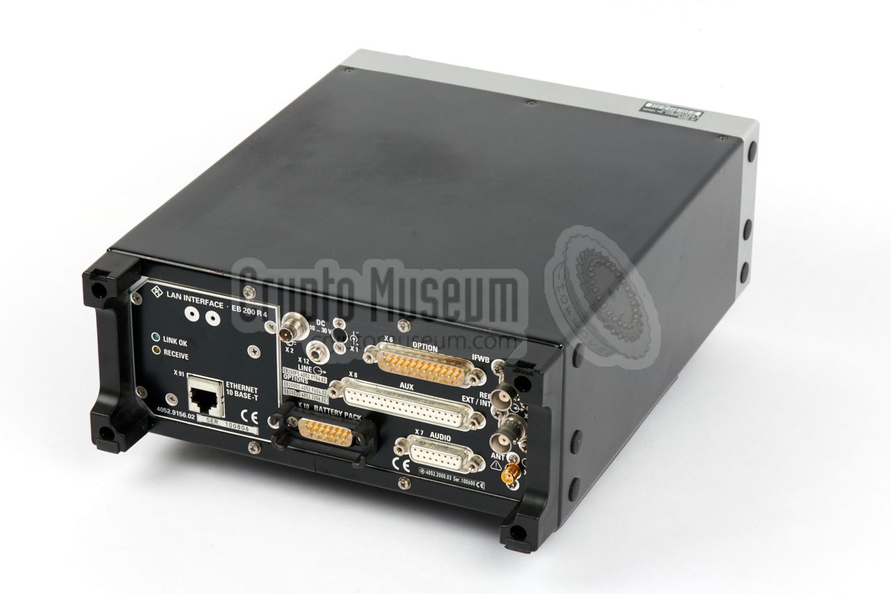
- LAN interface
With the (optional) LAN interface, communication is possible via 10-Base-T
Ethernet, using TCP/IP and the SCPI control protocol. This interface is
approx. 100 times faster than the RS-232 interface and allows real-time
transfer of the IF spectrum. When this option is installed, an RJ45 socket
marked X91 should be available at the rear, and the RS232 interface is
omitted. The receiver can also be controlled via an internet browser.
|
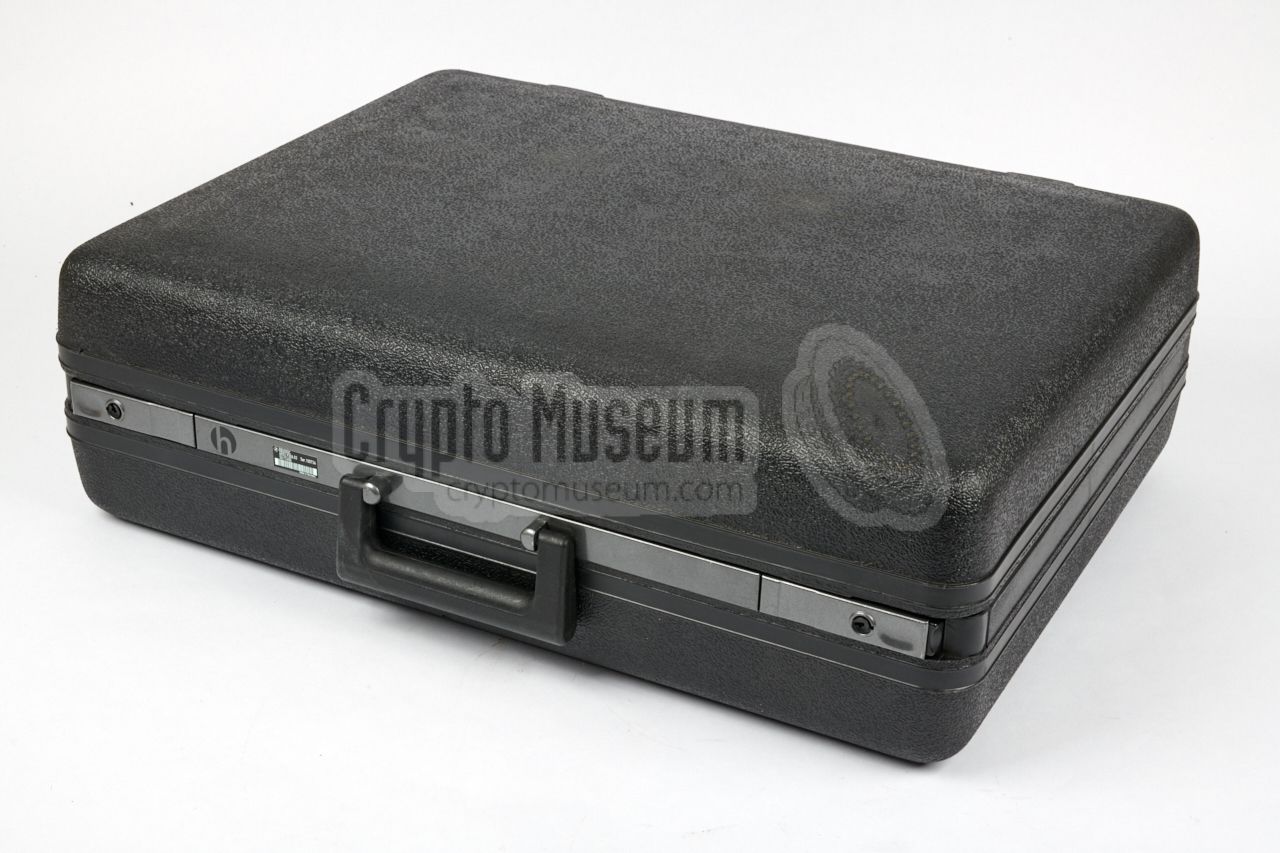
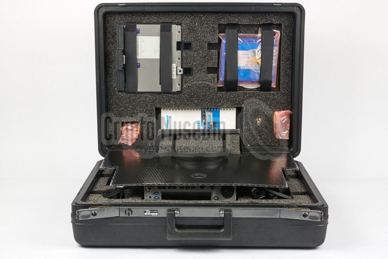
The actual receiver measures 270 x 210 x 88 mm and can be stowed in the
(optional) suitcase (see above).
When the battery pack is used, the hight
of the receiver is increased with the height of the battery pack and its
fittings. As a result, the foam in the suitcase may have to be adapted.
A standard EB-200 can be expanded with a LAN interface, an IF panorama,
and several soft-options, but these do not affect its size.
|
|
|
Due to space constraints, the EB-200 does not have internal batteries.
For desktop operation (or rackmount application),
it should be powered by an external DC
source between 11 and 30V DC, typically from by the original Deutronic
mains power supply unit (PSU) that delivers 24V DC.
This PSU can also be used for charging the (optional) battery pack (see below),
both separately and whilst connected to the radio.
|
|
|
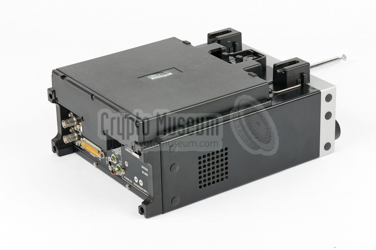
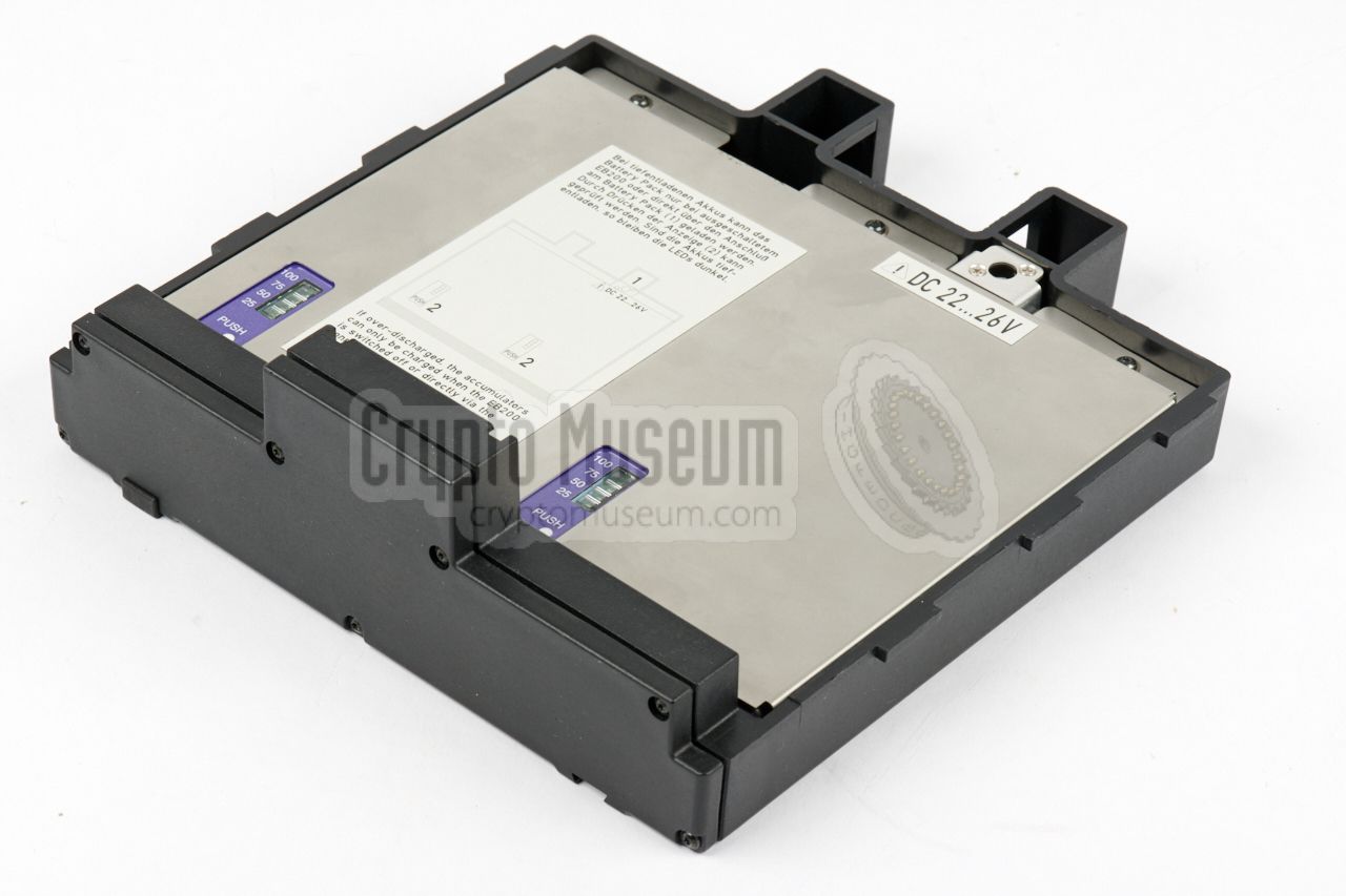
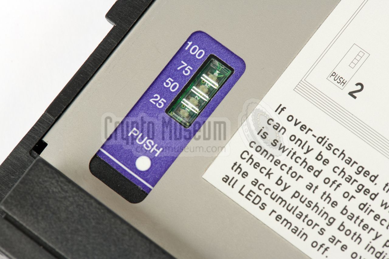
For portable use, the EB-200 can be expanded with an external (optional)
battery pack that is fitted at the bottom. It connects to the radio via
connector X10 at the rear. The battery pack contains two independent
batteries, each of which is monitored (and charged) separately.
The batteries can be charged 1 by a DV voltage between 22 and 26V, typically
provided by the external PSU (see above).
This can be done in-situ (whilst connected to the radio) or separately
by using the power socket on the battery pack.
|
|
|
-
Note that a deeply discharged (over-discharged) battery pack can only be
charged externally.
|
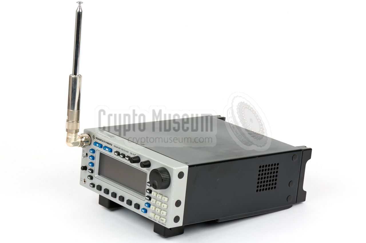
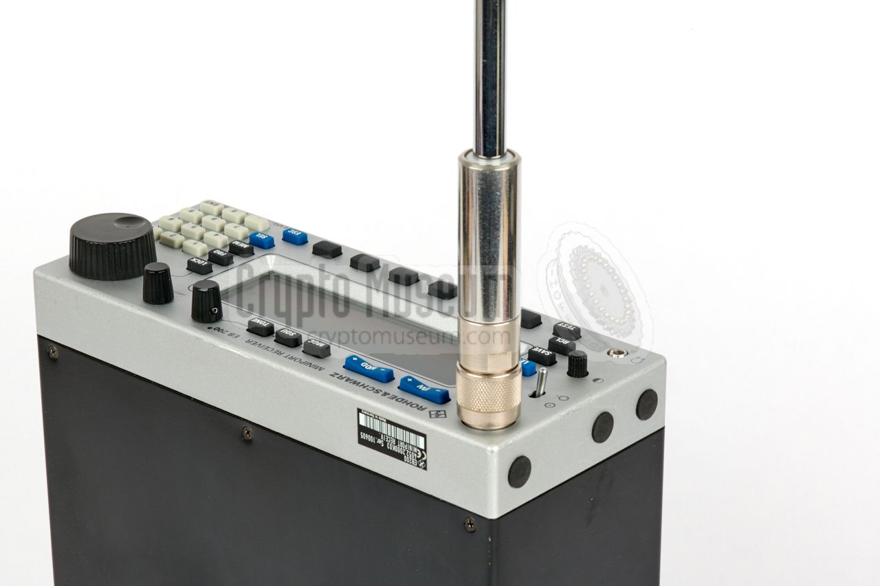
Although it is advised to use the EB-200 with an external antenna, or with
the special close-range HE-200 antenna set,
a telescopic antenna is
supplied for simple monitoring jobs. It can be connected directly at the
front panel.
As the original telescopic antenna is missing from our EB-200, we are
showing an alternative one here. When the radio is used in horizontal
position, a 90° N-type adapter is required.
|
|
|
|
By default, the audio output of the receiver is delivered to the
internal speaker, located at the right side of the device.
When the supplied pair of headphones – shown in the image on the
right – is connected to the 3 mm jack at the front panel,
the internal speaker is disconnected.
|
|
|
Depending on the version, a CD with additional software and the latest
firmware for the receiver was supplied. The disc also contains utilities
for updating the EB-200 from a PC and example code for using the
remote control facilities.
The last update is from 2006.
|
|
|
The receiver comes with a small Pocket Guide, in which the
most frequently used features are explained. It is printed on thick
paper [B].
For a more detailed
description of the many features of this receiver, a full operator's
manual is provided in digital format on CD.
➤ Download Pocket Guide
➤ Download full manual
|
|
|
|
|
Directional antenna
HE-200
|
|
|
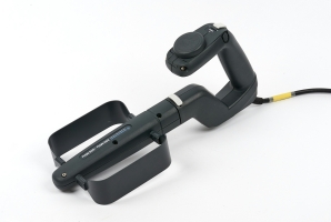
Especially for locating transmitters at very close range – for example
when searching for
covert listening devices (bugs)
in a room – the special
HE-200 antenna set was available. It consists of a pistol grip with a
built-in RF pre-amplifier and one or more plug-in antennas.
The set is similar to the earlier HE-100
– that was supplied available for the
EB-100 receiver
– but covers 20 MHz to 3 GHz (rather than 1 GHz).
The image on the right shows the HE-300,
which is the successor of the
HE-200 and covers a frequency range from 9 kHz to 7.5 GHz.
➤ More about the HE-100
➤ More about the HE-300
|
|
|
The EB-200 is an extremely complex device with many interacting circuits
and sub-circuits.
To explain its operation, we will use the simplified block diagram below.
Central to the system is the backplane with holds the parallel host (data) bus,
an I2C bus, a serial (data) bus, a junction bus and an audio bus.
The backplane is represented by the thick blue line in the diagram below.
All signal processing is above the backplane, starting with the
RF pre-selection stage at the top left.
Next is the RF-stage, which consists of two cascaded front-ends. The RF stage
delivers the 10.7 MHz IFWB signal for an external panorama viewer, and for
the digital IF stage. The IF stage further processes the data and delivers
the AF (audio) signal. It can be enhanced with an IF panorama
unit (shown at the top right) which can be further expanded with a
Digital Signal Processor (DSP).
Below the backplane is (from left to right) the front panel control unit (UI)
— it takes the input from the front panel and drives the LCD — the Central
Processing Unit (CPU), the internal power supply (DC/DC) and the junction
panel at the rear (I/O). At the bottom right are the remote control interfaces,
which are mutually exclusive. The radio either has RS232 or Ethernet I/O.
|
X1 DC power 11—30V X2 DC power 11—30V X4 External reference (10 MHz) X5 IF WB out (10.7 MHz) X6 Option X7 Audio X8 AUX X9 Serial RS-232 port 2 X10 Battery pack X12 Line out (stereo) X13 Antenna input for rackmount 1 X91 LAN interface (10 Base-T Ethernet) 2
|
-
Selected internally.
-
X9 and X91 are options and are mutually exclusive.
|
- GND
- J TXD
- J RXD
- J RTS
- J CTS
- J DSR
- GND
- not connected
- A RX
- not connected
- not connected
- S FRAME
- GND
- (+)5V
- not connected
- not connected
- not connected
- not connected
- not connected
- J DTR
- not connected
- not connected
- A TX
- S CLK
- S DATA
|
|
- Speaker EXT1
- AF GND
- AF SYM1
- not connected
- LOG
- SIGNAL
- FSK
- (+)5V
- Speaker EXT2
- AF MONO
- AF SYM2
- not connected
- JO1
- JO2
|
|
- DC Accu
- DC Accu
- GND
- GND
- DC Charge
- not connected
- SCLB
- /PWR_OFF
- DC Accu
- DC Accu
- GND
- GND
- DC Charge
- SDAB
- /PWR_ON
|
|
Frequency 10 kHz — 3 GHz Dynamic range -10 to +110 dBµV Modulation AM, FM, USB, LSB, CW, Pulse, I/Q Bandwidth 150 kHz to 120 kHz (10 steps) (15 with IF Spectrum option) IF output 10.7 MHz ± 5 MHz Digital outputs AF, I/Q Remote control RS232, IEC625 or LAN 1 Display Monochrome graphics, 240 x 64 pixels (with backlight) Dimensions 270 x 210 x 88 mm Weight 4 kg (5.5 kg with battery pack)
|
4052.4102.02 EB200-BP Battery Pack 4052.3206.02 EB200-SU IF Panorama 4052.9604.02 EB200-DS RF Spectrum DIGI-Scan 4052.9704.02 EB200-FS Field-Strength Measurement Software 4052.9804.02 EB200-CM Coverage Measurement Software 4052.9156.02 EB200-R4 LAN Interface 4052.9056.02 EB200-R2 Serial Interface (RS-232-C)
|
|
|
LAN software compatibility
|
|
|
- Radiolocation from 10 kHz to 3 GHz now with portable equipment
News from Rohde & Schwarz, Number 156, 1997/IV, pp. 4-6.
- Portable, mobile or stationary radiomonitoring...
News from Rohde & Schwarz, Number 161, 1999/I, pp. 25-26.
- Hard times for eavesdroppers
News from Rohde & Schwarz, Number 164, 1999/IV, pp. 24-25.
- Mini-Receivers: remote control lends weight to network role
News from Rohde & Schwarz, Number 165, 1999/V, pp. 16-17.
- Coverage and field-strength measurements with the mini-receiver
News from Rohde & Schwarz, Number 170, 2001/I, pp. 12-14.
- IF panorama option - nothing hidden in the spectrum
News from Rohde & Schwarz, Number 171, 2001/II, pp. 48-50.
|
|
|
|
Any links shown in red are currently unavailable.
If you like the information on this website, why not make a donation?
© Crypto Museum. Created: Wednesday 26 September 2018. Last changed: Sunday, 05 June 2022 - 10:26 CET.
|
|

|
|
|