|
|
|
|
|

|
UHF intercept receiver
Přístroj 1
was a UHF intercept receiver,
developed around 1968
in Czechoslovakia
by Správa 6 2 for use by the
secret intelligence agency (StB)
and by Správa 1 (espionage) in counter-counter-espionage operations.
The device was designed to receive a fixed frequency in the 465 MHz band
and was used in Paris (France) for monitoring communication of
the French counter-espionage.
|
The image on the right shows a typical Pristroj receiver that was normally
connected to a tape recorder. It has only two controls:
Volume and RF Gain, plus two indicators: Power and Record.
During the cold war, Czechoslovakia
had a large number of spies and secret agents on active duty in France. Although most of them worked under the
diplomatic cover of the embassey, nearly all of them were on the payroll
of the StB, the ZS GŠ or Správa 1.
As a result, many of them were followed by the French counter-espionage
as soon as they started walking the streets of Paris.
|
|
|
For covert communication between agents of the counter-espionage agency,
the French used portable radios that operated on 465 MHz. No encryption
was used on these voice channels, as the French believed that, due to the
very high frequency that was used, the signals would not be intercepted.
Communications receivers for these frequencies were not
mainstream at the time.
Přístroj was developed in-house by Správa 6, and
several units were
used simultaneously to monitor all radio channels of the French
counter-espionage. Each device was marked with one of the letters of
the alphabet, probably indicating the frequency.
The device was introduced in 1968 and was an instant
hit. It produced great intelligence on a daily basis for many years.
|
-
Přístroj is the Czech word for Device.
-
Správa 6 refers to Government Department 6: Communication Technology.
|
Despite its simple and almost boring look, Přístroj was an extremely
effective tool. Rather than using a Variable Frequency Oscillator (VFO),
each device was configured for a single frequency of the French
counter-espionage by means of a fixed crystal. As a result,
multiple devices
had to be used, usually powered by a common 12V DC power source.
The 465 MHz input of all devices came from a single antenna with a
distribution amplifier. The RF Gain can be adjusted at will.
The unit is switch on by turning the Volume knob away from the OFF-position.
The green LED will come on.
Whenever a sigal is intercepted, the red LED lights up and the message
will be heard through the speaker or the connected headphones. At the same
time a relay is activated, allowing an (optional) recorder to be switched
on as well (REC). This also allows unattended recording.
|
|
The receiver is housed in a modern modular aluminium enclosure that
measures only 27 x 18 x 7 cm. The top panel can be taken off by removing
four bolts at the corvers. Likewise, the bottom panel can be taken off
by removing the four feet on which the unit stands. This exposes a frame.
|
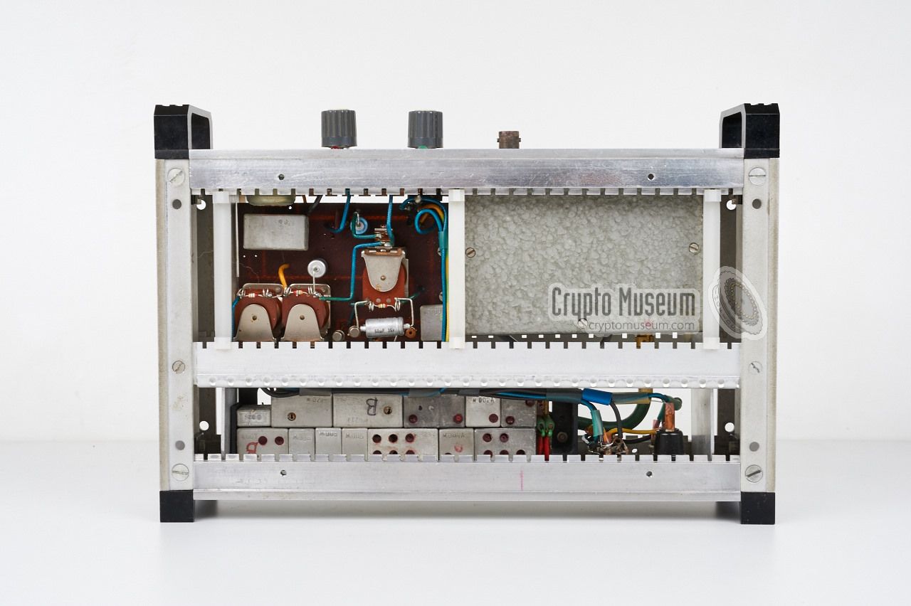
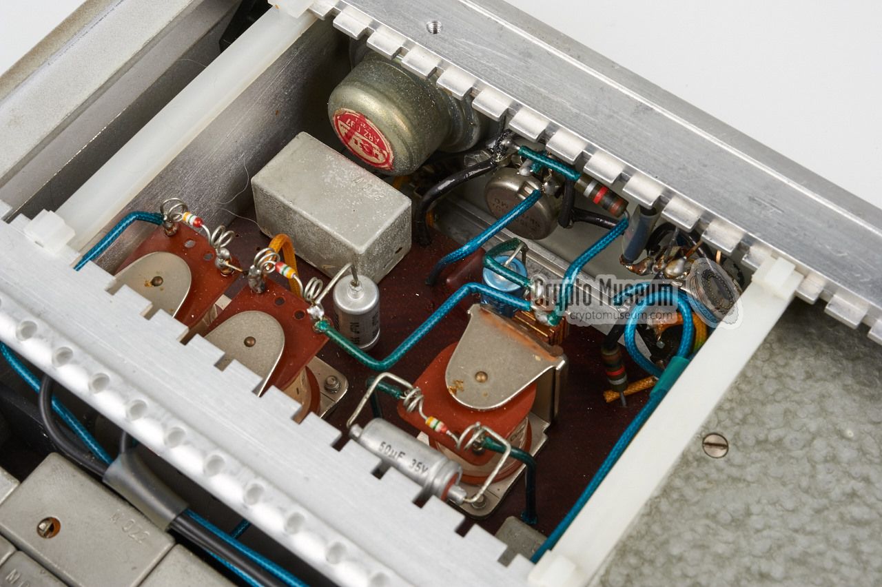
The electronics inside the frame can be divided into three modules,
each of which seems to be developed by a different design team.
At the front left is a grey hammerite metal box that contains a
downconverter.
It converts the 465 MHz signal into an easier to handle
74 MHz one.
At the front right is the control board
that holds three electric relays
with the driving transistors, an AF pre-amplifier
and the AF audio amplifier that delivers the speaker signal.
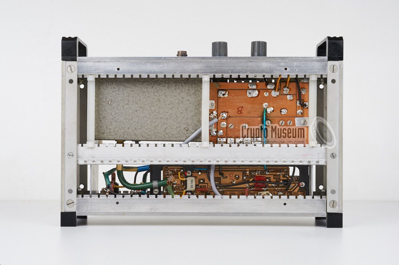
The actual 74 MHz receiver
is mounted on a subframe close to the rear, and has a highly modular design.
|
|
|
The modules are mounted onto a single PCB
that is marked with the project number TI-574B.
It incorporates a complete crystal-operated
double-superheterodyne receiver, with selective tone call, squelch and
switched output. Similar modules were used in the TI-574A transmitter
that was part of the
Štěnice radio bug.
The downconverter is known as project number TI-640A.
|
A complete Přístroj station consisted of five modules: the main
receiver (described here), a tape recorder (possibly an UHER Report 4000),
a central clock facility, a time-code inserter and a 12V
central power supply unit (PSU).
Only the actual 465 MHz intercept receiver (RX) is described here.
The receiver is build from various more or less standard components plus
a purpose built control board with several relays. The three main blocks
are shown in the diagram below. At the top left is the transverter that
converts the intercepted 465 MHz signal down to 74 MHz. This block is
known as project TI-640A. The 74 Mhz signal from the converter is fed into
a crystal-operated double superheterodyne receiver that is constructed
from a range of standard modules.
The receiver includes an automatic squelch, a single-time selective call
unit, an emitter follower (to drive a relay) and an audio amplifier that
delivers the LF output at speaker level. The standard modules from which
the receiver is constructed, allow a high degree of customisation and
flexibility, whilst reducing development time and cost. Similar modules
were used in various other devices, such as remote control units,
electronic dead letter boxes and radio bugs like
Štěnice.
|
|
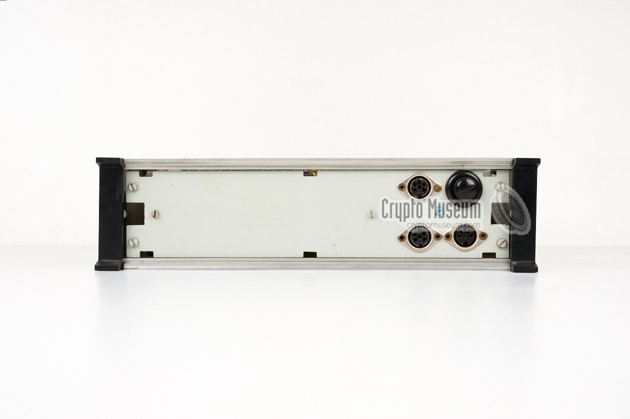
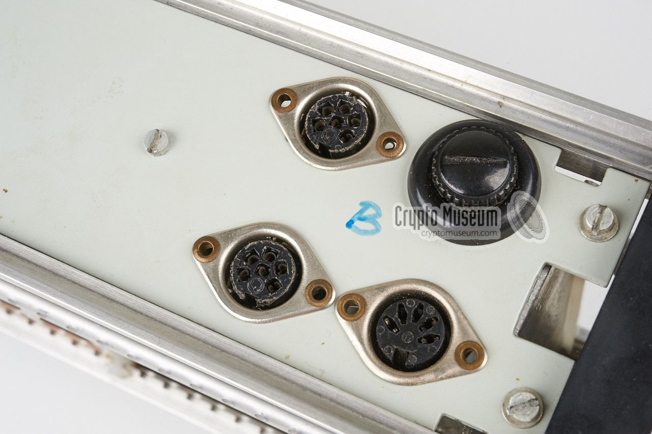
The device has three DIN sockets at its rear panel: one 3-pin 180° female
socket and two 6-pin 240° female sockets. The 3-pin socket carries the
audio at line level plus a relay contact. The two 6-pin socket are connected
in parallel (all 6 pins 1:1). These sockets are used for 12V DC power
input, line-level audio output and a relay contact for automatically
starting a tape recorder.
|
- Audio
- Ground
- Record (switched contact to ground)
|
|
- Audio (line out)
- -
- Ground
- -
- Record (switched contact to ground)
- +12V DC
|
|
TI-640A 465 MHz to 74 MHz downconverter TI-574B 74 MHz double superheterodyne FM receiver
|
- Anonymous, Přístroj 465 MHz intercept receiver - THANKS!
Receiver and documentation kindly donated by anonymous former user. July 2015.
|
|
|
|
Any links shown in red are currently unavailable.
If you like the information on this website, why not make a donation?
© Crypto Museum. Last changed: Saturday, 06 October 2018 - 16:02 CET.
|
 |

|
|
|