|
|
|
|
|

|
|
CIA NRP EC SRS-52 SRR-56 →
The SRR-52 has a built-in alarm function that produces a tone when the
receiver has accidently been tuned to a regular (non-TP) RF signal,
or when the audio-masking feature of the SRT-52 fails and the bug
loses its security. It also has a built-in test facility, that allows
the video encoder of the SRT-52
to be connected directly to the video
input of the SRR-52, thereby bypassing all RF components. And with the
supplied video detector is is possible to connect the RF output
of the SRT-52 to the video input of the receiver, thereby
bypassing the RF and IF stages of the SRR-52.
|
Development of the SRR-52 was started around 1966, with the first prototypes
being available in 1967. After a period of testing and improving, it
was in production from 1969 - 1970, after which
TP masking was
abandoned in favour of the RP and DP schemes, that were easier to implement.
In 1972, the SRR-145 converter
was added to expand the range to 1300-1600 MHz.
In 1975, the Automatic Gain Control (AGC) of the SRR-52 was modified by
Motorola
to make it immune to peak-pulse interference in urban areas,
caused by the ignition of cars and motorcycles [2].
|
|
|
The SRR-52 is very similar to the SRR-56,
which was introduced around the same time (1968) for use with bugs that
supported the
Rejected Pulse (RP) audio masking scheme,
such as the SRT-56.
In 1972, more than half of the existing SRR-52 receivers were retrofitted
with a modification that made it compatible with the audio masking schemes
of the SRT-56
and SRT-91.
The SRR-52 was eventually succeeded in 1973 by the
SRR-91 and in 1975 by the
more versatile modular SRR-90.
|
- SRR-52
Original version of the SRR-52, developed in 1967 and in production from
1969 to 1970. Covers the lower UHF band from 240 to 330 MHz, and can
demodulate TP-masked audio signals
(the so-called type 52 modulation).
Compatible with the SRT-52 transmitter.
- SRR-52-M
SRR-52, retrofitted 1 with a modification to allow demodulation of
RP-masked
and DP-masked audio signals.
This makes the receiver compatible
with the SRT-56
and partly 2 with the SRT-91.
With the SRR-145 converter it was also compatible with
the SRT-107.
|
-
More than half of the existing SRR-52 receivers were converted into an SRR-52-M
in 1972.
-
Only part of the frequency band of the SRT-91
is covered.
|
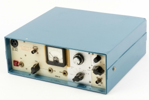
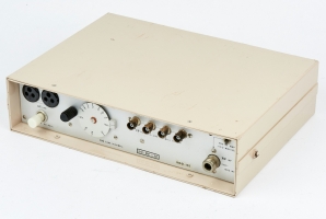
The SRR-52 is housed in a sturdy blue metal enclosure. It has all controls
and connections at its front panel, so that it can be used both horizontally
(as shown below) and vertically (with its control panel facing upwards).
The diagram below shows the layout of the modified SRR-52-M. The modification
was retrofitted in 1972 and involves the brighter part of the front panel.
The full 240-330 MHz frequency range is covered by one full
turn of the large knob at the right. It is marked in tens of MHz, with '0'
corresponding to 300 MHz. The MODE selector controls the function of the meter
and also selects the appropriate audio masking decoder (SRR-52-M only).
|
When tuned-in on an SRT transmitter, the tuning knobs above the MODE selector
should be used to adjust the timing of the pulsed signal. This means
getting a maximum reading on the meter. An alarm will be heard when the
timing is mis-adjusted or when audio masking facility fails.
The frequency range of the SRR-52 could be expanded by using an
SRR-145 down-converter. This makes the existing receivers suitable for
the reception of bugs in the 1300-1600 MHz range, such as the SRT-107
and the high-band versions of the
SRT-52
and the SRT-56
(see below).
|
|
|
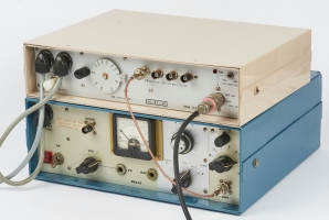
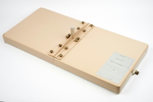
The SRR-145 has the same width as the SRR-52, so that it can be placed
conveniently on top of it. Both receivers have a small circular notch
at either side of the case, to which an optional carrying grip can be
attached, making the device 'portable'. In practice however, the
receivers were usually installed and operated from inside a common
Samsonite executive style briefcase.
|
|
The SRR-52-M is suitable for receiving and decoding the following transmitters:
|
-
SRS = Surveillance Radio Set.
|
In 1971, the CIA started using the newly allocated 1500 MHz band for
the use of covert listening devices. The diagram below shows how the
existing parts were used in the new setup. At the left is the
SRT-52 transmitter, in which the
SRK-29 RF-module has been replaced by an
SRK-145.
A small SRN-58 plexiglass antenna
transmits the 1500 MHz signal to the listening post (LP) where it
is picked up by an SRN-55 antenna, and passed on
to the SRR-145 down-converter. The latter converts
the 1500 MHz signal into 300 MHz, so that it can be decoded with the
SRR-52.
In the high-band setup, the SRR-52-M is also suitable for the reception of
the SRT-107,
which is in fact an integrated version of the SWE-56 video
encoder, the SRK-145 RF-module and the SRN-58 antenna. The diagram above
shows how the SRT-107 is used in this setup.
|
|
A complete SRR-52 listening post consists of one or more of the
following items:
|
At the heart of a listening post (LP) of the 52-system,
was the SRR-52 or SRR-52-M receiver featured on this page.
It covers 240 to 330 MHz, and is capable of receiving
TP-masked pulse transmitters
like the SRT-52.
The modified SRR-52-M is also suitable for the reception of
RP-masked pulse transmitters
like the SRT-56 and
(with the use of the SRR-145 down-converter)
the SRT-107.
➤ Look inside the SRR-52
|
|
|
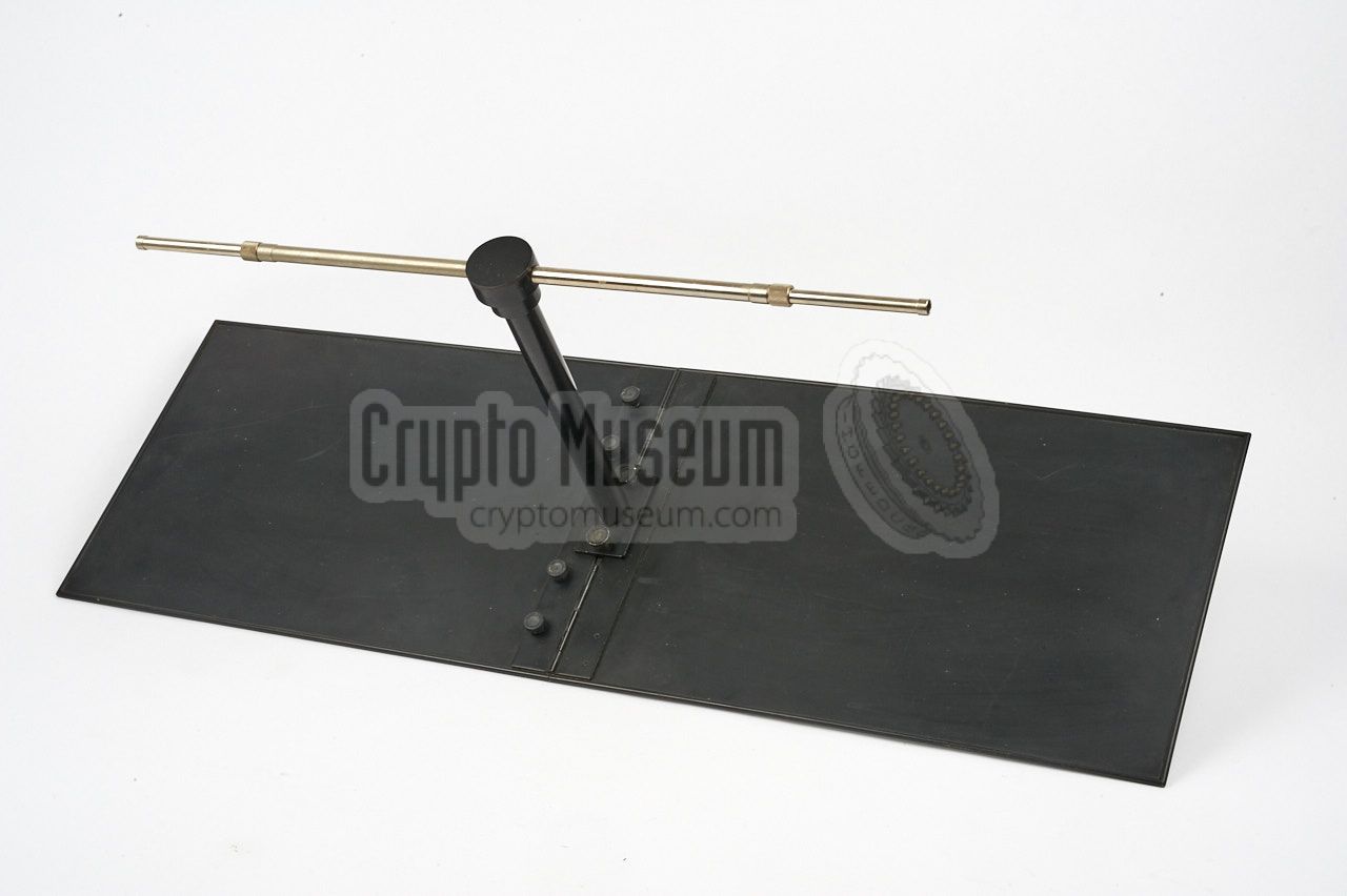
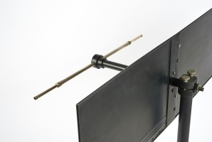
A suitable directional antenna for the SRR-52 listening post (LP)
is the SRN-9-L, or the later SRN-9. It offers a gain of 7 dB and is
in fact an adjustable dipole on a horizontal boom (which acts as a
balun), mounted in front of a reflector.
The antenna can be disassembled completely, and the reflector plane
can be folded at the centre, so that the entire unit can be stored inside
a regular briefcase, along with the SRR-52 receiver and its accessories.
➤ More information
|
|
|
The SRR-52 has two audio outputs: a fixed one for connection of a recording
device, and an adjustable one for connection of a pair of headphones.
Virtually any type of headphones with an impedance of 600Ω can be
used.
It was typically used with American military headphones of the era, such as
the one shown in the image on the right.
|
|
|
The SRR-52 has a direct video input on its front panel, which can be used
for testing the video encoder of an SRT transmitter. By connecting the video
output of the encoder directly to the video socket of the SRR-52, all RF
components (in the transmitter and the receiver) are bypassed.
By connecting the video detector, shown in the image on the right, to the
video socket of the SRR-52, the RF output of an SRT transmitter can be
converted directly into pulses (video), thereby bypassing the receiver only.
|
|
|
The frequency range of the SRR-52 (240 - 330 MHz) could optionally be
enhanced with the 1300 - 1600 MHz band, simply by inserting the SRR-145
down-converter shown on the right,
between the antenna and the receiver's input.
This was necessary for receiving SRT-52
and SRT-56 units that were
equipped with a high-band SRK-145 RF module.
It was also needed for the reception of the later
SRT-107 transmitters.
➤ More information
|
|
|
When using the SRR-145 down-coverter shown above,
the existing SRN-9 listening post antenna has to be replaced by
one that is suitable for the 1300 to 1600 MHz frequency
range.
The SRN-55 is a flat stacked-dipole antenna that covers the entire
range and offers a gain of approx. 17.5 dB.
➤ More information
|
|
|
Below is the block diagram of the Triple Pulse (TP) decoder of
the SRR-52. At the far left is the tuner, which consists of an RF
and an IF stage. It delivers a video signal that is fed to a slicer
of which the output contains clean groups of three pulses each.
Each group is then delayed, after which the image is added to its original,
in such a way that groups of five pulses are obtained.
The third pulse (which has become twice as high as a result of the addition),
is used to set a flip-flop. Likewise, the fourth pulse (with is position modulated)
is used to reset the flip-flop.
The output of the flip-flop is a pulse-width modulated signal, that
is fed to a quasi integrator followed by a peak detector and a sample-and-hold
circuit to fill the gaps between two samples. The result is a staircase
signal that resembles the shape of the original audio signal. A low-pass
filter is used to smoothen the signal before it is fed to the
audio amplifier at the bottom right.
|
|
The SRR-52 is extremely well built and is housed in a bright blue
metal enclosure. All parts are mounted to a strong metal chassis
that itself is mounted to the front panel. After removing four screws
around the edges of the front panel, and one at the rear,
the case shell can be removed.
|
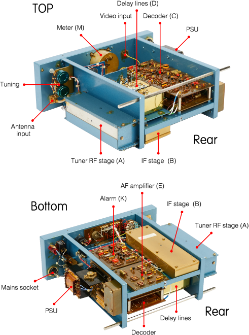
The image on the right shows the SRR-52 after the case shell has been
removed. When looking at the device
from the rear, it is obvious that
the case is divided into four sections, separated by metal
panels. The leftmost section contains the
power supply unit (PSU),
whilst the RF tuner is contained in a
separate enclosure at the right.
The large centre part of the receiver is divided in a upper and a lower
section. The lower section holds the IF/AF stages,
whilst the upper section
holds the audio masking decoders, with their
adjustable delay lines
visible at the rear right.
|
|
|
The SRR-52 was clearly developed with TEMPEST in mind. Unlike many
contemporary receivers, the front-end
was constructed in such a way that no signal from the local oscillator
(LO) would leak out through the antenna connector, which might otherwise
have revealed the LP's presence.
|
This also explains why the meter on the front panel is housed inside
a circular purpose-made brass enclosure. It prevents any internal
signal residue from leaking out through the fairly large hole in
the front panel. This also explains the brass pane
around the meter on the front panel.
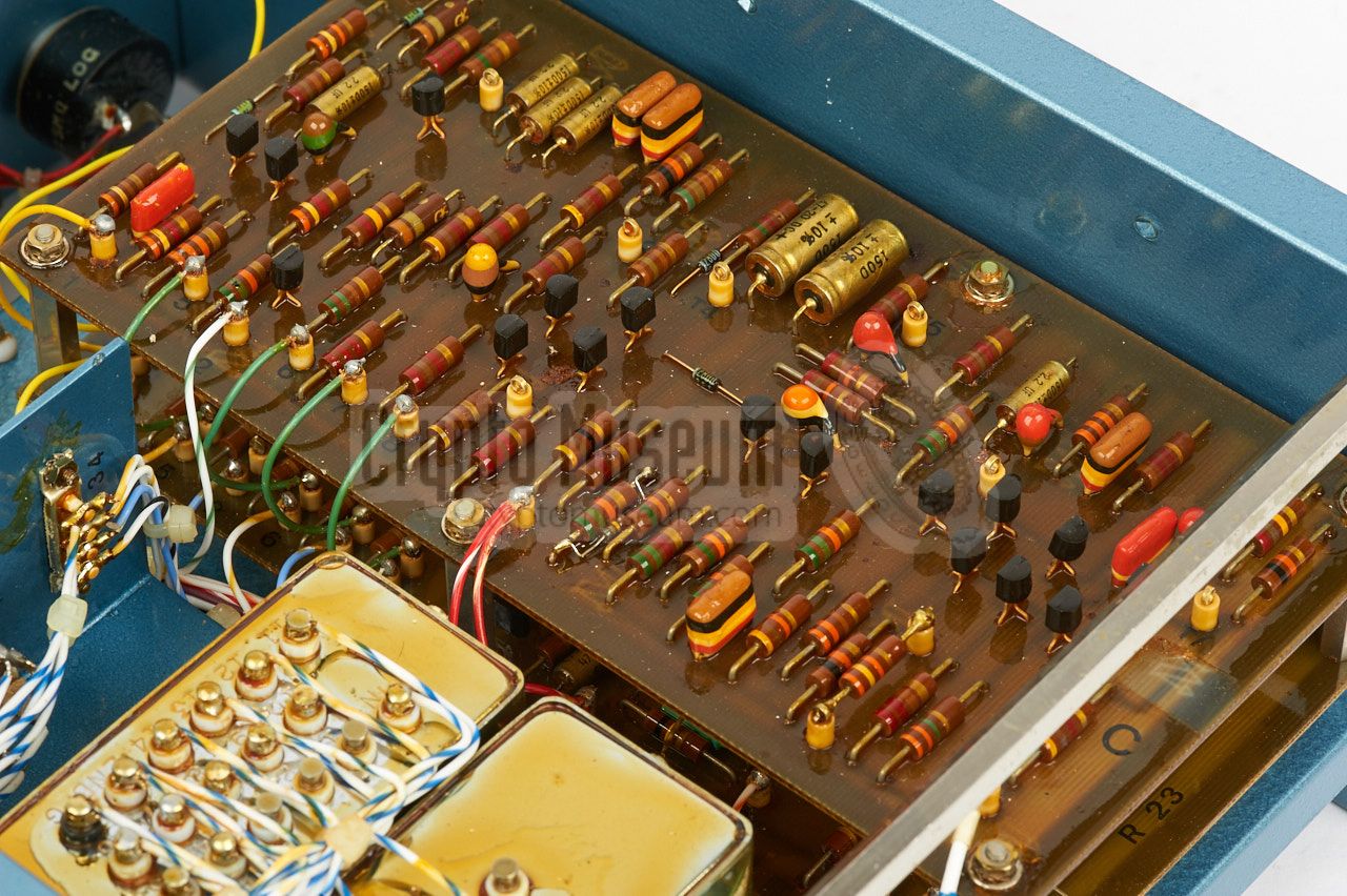
When the SRR-52 was modified in 1972, it was retrofitted with an
extra printed circuit board that was fitted below the existing
decoder (C). The new board has the same size as the existing one,
and supports bugs that use the
Rejected Pulse (RP)
and Dirty Pulse (DP) masking schemes.
|
|
|
On the modified SRR-52-M, switching between the two decoders is
done with the MODE selector that was given an extra setting.
In 52-mode it supports the old
Triple Pulse (TP) masking scheme.
This scheme is used by the SRT-52 transmitter.
In the new 56-mode, the receiver is suitable for the reception
of RP and DP masked transmitters, such
as the SRT-56 1 ,
the SRT-90 and
SRT-91.
|
-
In combination with the SRR-145,
the SRR-52 is also suitable for receiving and decoding the
SRT-107.
|
- Manual for SRT-52 and UWP-52 prototype equipment
CM302489/A, May 1967.
- Operating Manual for SRS-52 Equipment
CM302489/B, October 1968.
- Technical Manual for SRS-52 Equipment
CM302489/C, October 1968.
- Operating Manual for SRS-52 Equipment
CM302489/D, December 1968.
- Technical Manual for SRS-52 Equipment
CM302489/E, December 1968.
- Operating Manual for SRS-52 Equipment
CM302489/F, January 1969.
- Technical Manual for SRS-52 Equipment
CM302489/G, January 1969.
- Operating Manual for SRS-52 Equipment
CM302489/H, October 1969.
- Technical Manual for SRS-52 Equipment
CM302489/I, October 1969.
|
- NRP/CIA, Collection of documents related to SRS-52
Crypto Museum Archive, CM302489 (see above).
- NRP/CIA, Collection of documents related to AGC ignition interference
Crypto Museum Archive, CM302626.
|
|
|
|
Any links shown in red are currently unavailable.
If you like the information on this website, why not make a donation?
© Crypto Museum. Created: Sunday 16 April 2017. Last changed: Sunday, 25 December 2022 - 11:58 CET.
|
 |

|
|
|